Essex Electronics SKE-34B Quick guide

Essex Electronics, Inc. | 805.684.7601 | 800.KEY-LESS | fax 805.684.0232 | keyless.com
INSTALLATION & INSTRUCTION MANUAL
SKE Series
12-Pad

Essex Electronics, Inc. | 805.684.7601 | 800.KEY-LESS | fax 805.684.0232 | keyless.com
i
All rights reserved. No part of this documentation may be repro-
duced in any form, without prior written consent of Essex Electron-
ics, Inc. Essex Electronics shall not be liable for errors contained in
this manual. The information in this document is subject to change
without notice. Essex Electronics, Inc. reserves the right to modify
this documentation and to make improvements or changes to the
product(s) contained in this documentation at any time.
Document Information
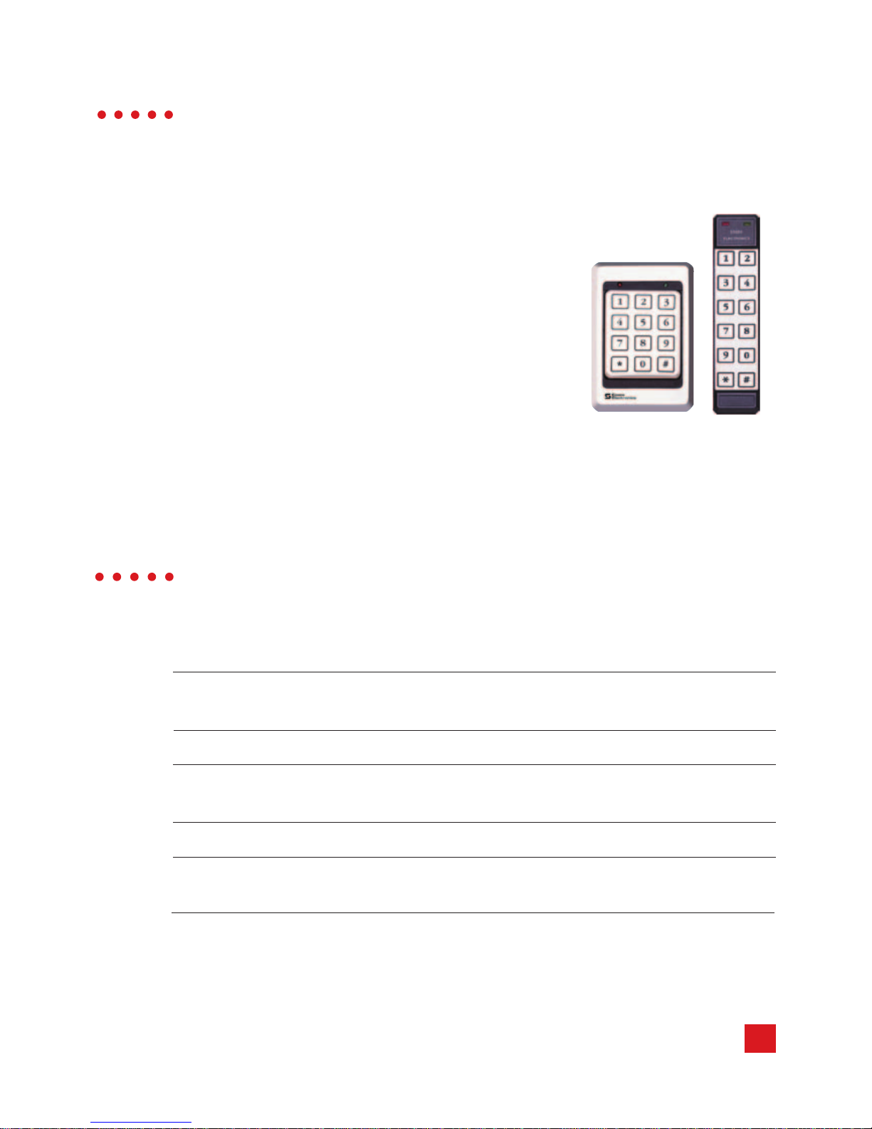
IOMK1 Installation/Operations Manual for the SKE Series 12-Pad
3x4 and 2x6 - December 2014. This documentation is also appli-
cable to prior revisions except where noted.
Trademarks
Keyless Entry® is a registered trademark of Essex Electronics, Inc.
Certications
The SKE-34 is listed by CSA for Elevator Equipment. CSAB44.1-04/
ASME-A17.5-2004. Class 2411 02.
Contact Information
Essex Electronics, Incorporated
1130 Mark Avenue, Carpinteria, CA 93013
(805) 684-7601 or (800) 539-5377 (KEY-LESS)
FAX (805) 684-0232
Website: keyless.com
Copyright© 2011 Essex Electronics, Inc. All rights reserved.
SKE Series 12-Pad
Self-Contained Keyless Entry® System With Relay

Essex Electronics, Inc. | 805.684.7601 | 800.KEY-LESS | fax 805.684.0232 | keyless.com
ii
Introduction....................................................................................1
Overview - The SKE Series.............................................................1
Keypad ............................................................................................1
Keypad Specications .....................................................................1
Keypad Part Numbers.....................................................................2
Keypad Connector Diagram.........................................................3
Keypad Conguration...................................................................5
Self-Contained Keyless Entry® System With Relay...................9
Specications ..................................................................................9
Conguration .................................................................................10
Programming Overview..............................................................11
Programming System Setup ......................................................12
Normal System Operation ..........................................................17
Keypad LED Status Indicators.......................................................17
Tamper Alarm ................................................................................17
Programming Individual Users ..................................................18
Warranty & Repairs .....................................................................24
Table of Contents

Essex Electronics, Inc. | 805.684.7601 | 800.KEY-LESS | fax 805.684.0232 | keyless.com
iii

1
Essex Electronics, Inc. | 805.684.7601 | 800.KEY-LESS | fax 805.684.0232 | keyless.com
Introduction
Overview – The SKE Series 12-Pad
3x4 Keypad (left)
and 2x6 Keypad
(right)
The Essex SKE Elevator Series All-In-One
12-Pad Self-Contained Keyless Entry®
System is an extremely versatile Keypad that
can be congured in the eld. It has one built-
in relay. It is ideal to control one lock, either
fail safe or fail secure. It can also trigger
a contact closure to activate an automatic
door opener or gate operator. There are
two additional open collector outputs. With
2 installer-provided external relays, up to 3
devices can be controlled.
Input Voltage: 5VDC or 12 to 24VDC (Jumper
Selectable)
Standby Current Draw: 25mA
Outputs: 1 Relay, 24VAC/DC Max, 2AMax; 2
Open Collector, 1/4AMax to Ground
Keypad Switch Life: >1 Billion Cycles
Keypad Operating Environment: -40°C to +70°C (-40°F to +160°F),
100% Relative Humidity
continued next page
Keypad

Essex Electronics, Inc. | 805.684.7601 | 800.KEY-LESS | fax 805.684.0232 | keyless.com
2
Keypad Part Numbers
3x4 Keypad
SKE-34B Brass Finished* Bezel
SKE-34S Stainless Steel Bezel
SKE-34K Black Bezel
SKE-34X No Bezel
2x6 Keypad
SKE-26B Brass Overlay
SKE-26I Illuminated
SKE-26S Stainless Steel Overlay
SKE-26R Braille Overlay
*Bezel is brass in appearance.Actual bezel is PVD-coated stainless
steel.
3x4 Keypad Dimensions: 5-1/8”H x 3-3/8”W x 7/16”D
(13 x 8.6 x 1.1 cm)
2x6 Keypad Dimensions: 7-1/8”H x 1-3/4”W x 3/4”D
(13 x 8.6 x 1.1 cm)
3x4 Keypad Weight: 16 oz (454 gm)
2x6 Keypad Weight: 4.4 oz (125 gm)
LED’s: 1 Red, 1 Green

3
Essex Electronics, Inc. | 805.684.7601 | 800.KEY-LESS | fax 805.684.0232 | keyless.com
Keypad Connector Diagram
BLACK- Ground
YELLOW- Anti Tailgate
By adding a door
monitor switch between YELLOW and BLACK, the door will relock
immediately after opening. If the third output is set up as an Internal
Alarm, this switch will trigger the alarm if the door is opened without
a code or if the door is left open longer than the Door Ajar Time
setting.
CONFIGURATION
PINS- “CONFIG” VOLTAGE SELECT DC ONLY
(Do NOT apply voltage)
12-24V (default), 27VDC Max -
Jumper on 1 pin only
5V- Jumper on both pins
YELLOW-Anti
Tailgate/InternalAlarm
(Do NOT apply voltage)
PINK- Remote Bypass
(Do NOT apply voltage)
BLUE- Common
BROWN- 24-hrAccess (Do
NOT apply voltage)
TAN- Earth Ground
BLACK- Ground
ORANGE- Program (Do NOT
apply voltage)
VIOLET- Normally Open
RED- Input Voltage
WHITE- OutputA
GREEN- Output B
NOTE: The 2x6 connector is rotated 180 degrees.
CAUTION: Do NOT run this low voltage wiring in conduit with or
adjacent to line voltage wiring.
GRAY- Normally Closed

Essex Electronics, Inc. | 805.684.7601 | 800.KEY-LESS | fax 805.684.0232 | keyless.com
4
PINK- Remote Bypass
Connect a Normally Open push button between PINK and BLACK to
trigger the main output for its normal Door Open Time setting.
ORANGE- Set Up Programming
Momentarily connecting ORANGE to BLACK puts the unit in Set Up
Mode (same as entering * 3, Master Code #).
BROWN- 24-hour Access
If Time Clock is enabled in Set up (page 16) and the BROWN wire
is grounded, all codes work normally. When the BROWN wire is
not grounded, only those codes with 24-hour Access Authorization
(page 17) will function.
Internal Relay Wiring Diagram
12-24VDC
Power
Supply
RED
BLACK
YELLOW
BLUE
VIOLET
GRAY
FAIL
SECURE
FAIL
SAFE
MOV
K
E
Y
P
A
D
12-24VDC
Power
Supply
VIOLET
YELLOW
BLACK
RED
BLUE
K
E
Y
D
P
A
Across
Existing
Push
Button
TYPICAL LOCK HOOK-UP TYPICAL GARAGE DOOR
or GATE HOOK-UP
+
-
+
-
MOV
TAN Earth Ground TAN Earth Ground

5
Essex Electronics, Inc. | 805.684.7601 | 800.KEY-LESS | fax 805.684.0232 | keyless.com
Voltage Selection
The factory default setting for the Keypad voltage is 12-24VDC.
Verify that the jumper is removed or placed over only one pin. For
5VDC, the jumper should be placed across both pins. If changing
the voltage is necessary, make sure the power is removed rst.
Keypad Output Selection
THE KEYPAD OUTPUT IS FACTORY CONFIGURED AND DOES
Once the voltage jumper is veried or correctly set (see above):
1. Remove power.
2. Jumper the two pins above the connector labeled “CONFIG.”
3. Apply appropriate power. (You should hear 4 beeps and the
RED LED will ash and the GREEN LED will be solid).
4. Now that the Keypad is in conguration mode, select the de-
sired output by entering the conguration number followed by #.
a. Keypad Output
KeypadOutput Conguration
Self-Contained- Non-encoded 99 #
b. (OPTIONAL) To change the audible beep, enter
Code AudibleBeep
201 # Normal Beep (factory default)
200 # Short Click (quieter)

Essex Electronics, Inc. | 805.684.7601 | 800.KEY-LESS | fax 805.684.0232 | keyless.com
6
c. (OPTIONAL) To change the illumination on the SKE-26
only, enter the code as follows:
Code StandbyMode NormalOperation
210 # Off (factory default) Off (factory default)
211 # Off Dim
212 # Off Bright
213 # Dim Dim
214 # Dim Bright
You should hear 3 beeps indicating successful conguration
(the RED LED will continue to ash and the GREEN LED will be
solid). If you hear a long error beep, re-enter the conguration
number followed by #.
5. Remove power.
6. Remove conguration jumper.
7. Re-apply power.
: Once the conguration is selected, you must re-
move power, remove the conguration jumper and then re-apply
power in order to complete the conguration procedure. Note: If
the conguration jumper is not removed, the LED’s will ash and
the Keypad will beep continuously.
Keypad Reset
In certain cases you may want to erase all user codes and restore
system defaults. To perform this procedure:

Essex Electronics, Inc. | 805.684.7601 | 800.KEY-LESS | fax 805.684.0232 | keyless.com
CAUTION: This procedure completely erases the memory and
restores factory defaults!!! Once the memory is cleared, all pro-
grammed User Codes are erased and factory default settings are
restored.
1. Remove power.
2. Jumper the two pins above the connector labeled “CONFIG.”
3. Apply appropriate power. (You should hear 4 beeps and the
RED LED will ash and the GREEN LED will be solid).
4. Once the Keypad is in conguration mode, enter 0099#. The
Keypad will beep twice and both LEDs will ash for approxi-
mately 10 seconds. (During this time, the Keypad will appear
dead. Do NOT remove power!!!)
5. Wait and you will hear 4 beeps and the RED LED will ash and
the GREEN LED will be solid.
6. Enter the conguration number followed by #.
a. Keypad Output
KeypadOutput Conguration
Self-Contained - Non-encoded 99 #
b. (OPTIONAL) To change the audible beep, enter
Code AudibleBeep
201 # Normal Beep (factory default)
200 # Short Click (quieter)

Essex Electronics, Inc. | 805.684.7601 | 800.KEY-LESS | fax 805.684.0232 | keyless.com
8
c. (OPTIONAL) To change the illumination on the SKE-26
only, enter the code as follows:
Code StandbyMode NormalOperation
210 # Off (factory default) Off (factory default)
211 # Off Dim
212 # Off Bright
213 # Dim Dim
214 # Dim Bright
You should hear 3 beeps indicating successful conguration
(the RED LED will continue to ash and the GREEN LED will be
solid). If you hear a long error beep, re-enter the conguration
number followed by #.
7. Remove power.
8. Remove conguration jumper.
9. Re-apply power.

9
Essex Electronics, Inc. | 805.684.7601 | 800.KEY-LESS | fax 805.684.0232 | keyless.com
Self-Contained Keyless Entry®
System With Relay
Input Voltage: 5VDC or 12 to 24VDC (Jumper
Selectable)
Standby Current Draw: 25mA
Outputs: 1 Relay, 2A24V Max; 2 Open Collec-
tor, 1/4AMax to Ground
Programmable Output: 1 to 99 seconds
(Door Open Time) Default - 5 seconds
Latching: Off (Default), Manual (Toggle On/Off)
Timed
# of Users: 502 (1 Master User, 500 Users,
1 Temporary User
Code Length: 3 to 8 Digits
Default Master Code: 1-2-3
TamperAlarm: 4 Incorrect CodeAttempts
Access Code Protection: Non-Volatile Memory

Essex Electronics, Inc. | 805.684.7601 | 800.KEY-LESS | fax 805.684.0232 | keyless.com
10
Input Requirements
The SKE Series accepts 5VDC or 12 - 24VDC. System current
draw (max) is as follows:
Standby: 25mA
During Operation: 100mA
Output Capabilities
SPDT relay rated at 24V 2A Max.
Output A
A transistor output intended to drive a relay that can be programmed
for one of the following:
1. CCTV or Light Controller - First key press triggers a Timed Out-
put (1 to 99 seconds).
2. Auxiliary Output - Manual Control or Timed Output (1 to 99 sec-
onds).
3. Second Door - Users can be assigned to open a 2nd door.
4. Doorbell - Press # at the Keypad to trigger a 1 second output for
a doorbell (not included).
Output B
A transistor output intended to drive a relay that can be programmed
for one of the following:
1. CCTV or Light Controller - First key press triggers a Timed Out-
put (1 to 99 seconds).
2. Auxiliary Output - Manual Control or Timed Output (1 to 99 sec-
onds).

11
Essex Electronics, Inc. | 805.684.7601 | 800.KEY-LESS | fax 805.684.0232 | keyless.com
3. Third Door - Users can be assigned to open a 3rd door.
4. Internal Alarm System - Detect Break-in, Door-ajar & Tamper.
5. Doorbell - Press # at the Keypad to trigger a 1 second output for
a doorbell (not included).
Programming Overview
There are two programming commands used with the SKE 12-Pad
Self-Contained Keyless Entry® System.
*3 is the Programming System Setup (page 12).This programming
command allows the programming of the Master Code, setting the
main relay opening time, allows latching (toggling) of the main relay,
etc.
*1 is the Programming Command for programming user codes
(page 18). When programming the user codes, you have the ability
to assign users authorizations. You can authorize a user to latch (if
the system was set up to latch in the *3 programming sequence),
you can allow a user to program or delete codes or activate one of
the other outputs, etc.
The SKE-12 Pad is congured at the factory. Under normal
installation, there is no need to Congure or Reset the keypad
unless the Beeper needs to be quieter or the Illumination needs to
be activated on the SKE-26 only.
The Default Master Code is: 1 2 3
The Relay On Time is: 5 sec

Essex Electronics, Inc. | 805.684.7601 | 800.KEY-LESS | fax 805.684.0232 | keyless.com
12
Programming System Setup
The System Setup can only be modied if you know the Master Code.
When the system is initially set up, the default system settings should be
reviewed prior to other programming.
1. Enter * 3
2. Enter the Master Code followed by #
Example: * 3 1 2 3 #
This opens programming and causes:
3. Proceed to one of the following eight programming options:
ChangingtheMasterCode(Default:1,2,3)
a. Enter 1 #
b. Enter the New Master Code followed by #
c. Return to Step 3 or enter * * to exit programming.
KeypadStatusAfterStepCompletion
Step Beep Red LED Green LED
a Double Fast Flash Slow Flash
b Triple Fast Flash Solid
Note: If you forget the Master Code, momentarily ground the
ORANGE wire. This will take you to Step 3 of Programming System
Setup. Once you enter setup mode, you have 30 seconds to begin the
program sequence.
Red LED Green LED
Fast Flash Solid

13
Essex Electronics, Inc. | 805.684.7601 | 800.KEY-LESS | fax 805.684.0232 | keyless.com
SettingtheMainDoorOpenTime(Default:5Seconds)
a. Enter 2 #
b. Enter the desired Door Open Time (1-99 seconds), followed by #
Example: 2#15# (15 sec. Door Open Time)
c. Return to Step 3 or enter **to exit programming.
KeypadStatusAfterStepCompletion
Step Beep Red LED Green LED
a Double Fast Flash Slow Flash
b Triple Fast Flash Solid
SettingLatchingOption(Default:Off)
a. Enter 3 #
b. Select the desired latching option:
Off- 0 #
Manual- 9 9 #
Timed- Enter the desired time interval in hours (1-98), followed
by #.
Example: 3 # 8 # (Sets timed latching for 8 hrs)
c. Return to Step 3 or enter **to exit programming.
KeypadStatusAfterStepCompletion
Step Beep Red LED Green LED
a Double Fast Flash Slow Flash
b Triple Fast Flash Solid
ConguringOutputA(Default:Aux#1)
a. Enter 4 #
b. Select one of the following:
CCTV/ExternalLight
1) Enter 1 #

Essex Electronics, Inc. | 805.684.7601 | 800.KEY-LESS | fax 805.684.0232 | keyless.com
14
2) Enter the desired On Time (1-99 seconds), followed by #
Example: 4#1#15#
(Sets CCTV/Light Option for 15 seconds)
AuxiliaryDevice#1
1) Enter 2 #
2) Enter the momentary output time (1-99 seconds), followed by
#; -or- Enter 0to set the auxiliary device for Manual Opera-
tion (ON/OFF), followed by #
Example: 4 # 2 # 0 #
(SetsAuxiliary Device with Manual Operation)
SecondDoor
1) Enter 3 #
2) Enter the desired Door Open Time (1-99 seconds), followed
by #
3) Select the desired latching method:
Off- 0 #
Manual- 9 9 #
Timed- Enter the desired time interval in hours (1-98),
followed by #
Example: 4#3#5#99#
(Sets Second Door with 5 second Door Open Time and
Manual Latching)
Doorbell
1) Enter 4 #
c. Return to Step 3 or enter **to exit programming.
KeypadStatusAfterStepCompletion
Step Beep Red LED Green LED
a Double Fast Flash Slow Flash
1) Double Fast Flash Fast Flash
2) Triple Fast Flash Solid

15
Essex Electronics, Inc. | 805.684.7601 | 800.KEY-LESS | fax 805.684.0232 | keyless.com
ConguringOutputB(Default:CCTV)
a. Enter 5#
b. Select one of the following:
CCTV/ExternalLight
1) Enter 1 #
2) Enter the desired On Time (1-99 seconds), followed by #
Example: 5#1#15#
(Sets CCTV/Light Option for 15 seconds)
AuxiliaryDevice#2
1) Enter 2 #
2) Enter the momentary output time (1-99 seconds), followed by
#; -or- Enter 0to set the auxiliary device for Manual Opera-
tion (ON/OFF), followed by #
Example: 5#2#0#
(SetsAuxiliary Device with Manual Operation)
ThirdDoor
1) Enter 3 #
2) Enter the desired Door Open Time (1-99 seconds), followed
by #
3) Select the desired latching method:
Off- 0 #
Manual- 9 9 #
Timed- Enter the desired time interval in hours (1-98), fol-
lowed by #
Example: 5#3#5#99#
(Sets Second Door with 5 second Door Open Time and
Manual Latching)
Doorbell
1) Enter 4 #

Essex Electronics, Inc. | 805.684.7601 | 800.KEY-LESS | fax 805.684.0232 | keyless.com
16
InternalAlarm
1) Enter 5#
2) Enter the desired DoorAjar Time (1-99 seconds), followed
by #
Example: 5#5#10#
(Sets InternalAlarm with 10 second DoorAjar Time)
Output is normally ON and turns OFF when triggered.
c. Return to Step 3 or enter **to exit programming.
MasterCodeDoorUnlockOption(Default:Allow)
a. Enter 6 #
b. Enter 0 # to prevent the master code from unlocking the door.
c. Enter 1 # to allow the master code to unlock the door.
d. Return to Step 3 or enter **to exit programming.
TimeClockInput(Default:Prevent)
a. Enter 7 #
b. Enter 0 # to prevent lockout
c. Enter 1 # to lockout all users that do not have 24 hour option
enabled.
d. Return to Step 3 or enter **to exit programming.
This manual suits for next models
7
Table of contents
Other Essex Electronics Keypad manuals