Stereo-Mode (5-Channel - with Front-/Rearsystem and Subwoofer)
5-
Speaker wiring and Connection
Channel Amplifier SX-5800
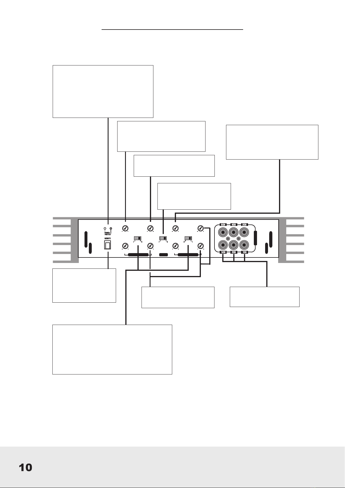
X-Over- (Front-/Rearsystem 1 up to 4 Channel)
•When you use bigger speaker systems (Ø20cm plus),set on FULL RANGE-position (FULL RANGE).
•When you use smaller speaker systems (Ø8.7cm - Ø16cm), set on HIGHPASS- position (HIPASS). The cut-off frequency should be
between 60Hz - 150Hz. It is controlled by the HIPASS-regulator.
Subwoofer (Channel 5)
• The cut-off frequency should be between 60Hz - 150Hz. It is controlled by the Lowpass-regulator.
Bass EQ-(Channel 5)
• Allows you to adjust the bass boost from 0dB up to 12dB.
Caution! Please use the Bass-Boost carefully. The additional boost may result in clipping or overload.
Subsonic-filter (Channel 5)
• Eliminates the lowest frequencies to protect your Subwoofer from damages. Cut-off frequency should be between
20Hz and 55Hz
Level
• Turn the INPUT LEVEL control on the amplifier to 5V position.
• Turn the head unit volume control to about 80-90% of its full setting.
• Turn the INPUT LEVEL control clockwise until you hear some distortion.
• Then turn back the INPUT LEVEL control slightly until you can hear clean sound.
Mode
• Set mode switch on 5CH-position
•
•
Interconect Cable checklist :
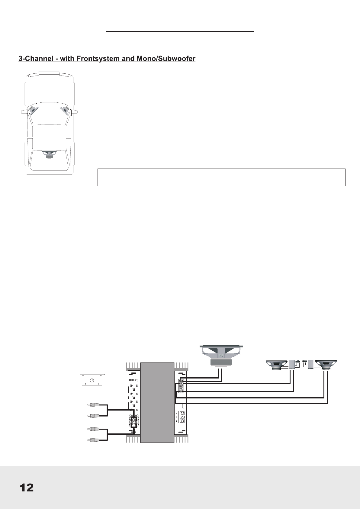
• Connect the RCA outputs from head unit with the RCAInputs (LINE INPUT 1CH&2CH / 3CH&4CH) of
the 4 Channel amplifier with two RCA Cables.
• Connect the RCA outputs of the (LINE OUT) 4-Channel Amplifier with the RCAinputs(LINE INPUT) of
the 1-Channel/Mono amplifier with an RCA cable.
• Connect the Front- & Rear-Speakers with a good RCA cable with the speaker outputs (SPEAKER
OUTPUT/ + 1CH -, + 2CH -, + 3CH -, + 4CH -) of the 4-Channel amplifier.
• Connect the Subwoofer with a good RCA Cable with the Speaker outputs (SPEAKER / + -) of the 1-
Channel/Mono Amplifier.
• The minimum final speaker impedance must not be below 2 Ohm per channel. Too low speaker loads
result in too high heat dissipation and may cause the amplifier run into protection.
• Please observe speaker channel and polarity as printed by the speaker terminal
•
•
•
•
•
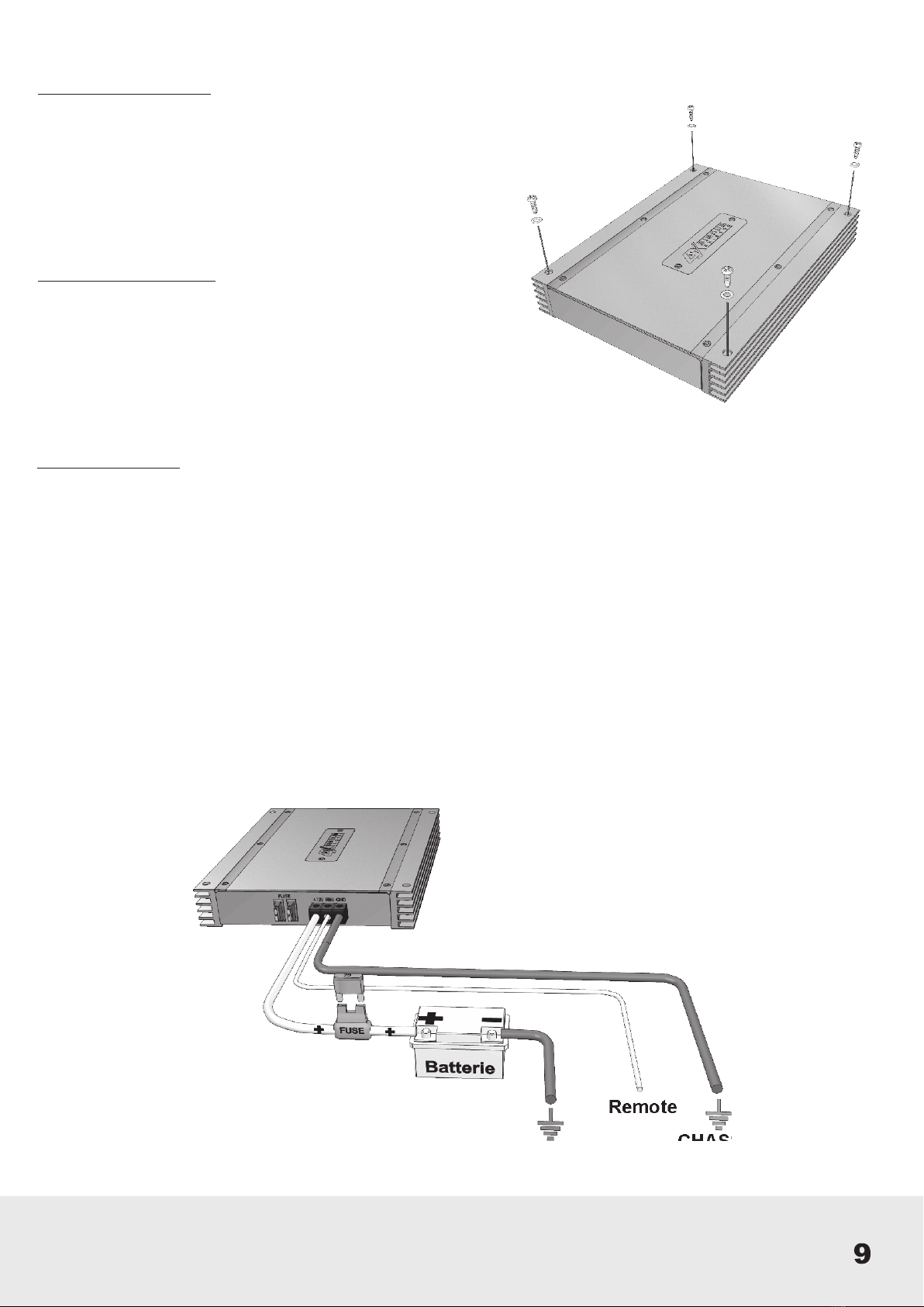
BATT+12V REMOTE GND SPEAKEROUTPUT
+ +
+ + +
-
--
- -
FUSE
3/4CH CONTROLS 1/2 CH CONTROLS
MODE
10Hz 150Hz 10Hz 50Hz 5V 0,2V
30Hz 150Hz 0dB 12dB 15Hz 50Hz 5V 0,2V
LPF BASSEQ SUB SONIC LEVEL
FULL HPF 5CH HPF FULL HPF
X-OVER X-OVER
LEVEL
5V 0,2V
L
R
LEVELINPUT
REMOTE
0dB 12dB
Subwoofer
2 - 8 Ohm Front-Speakers
4 - 8 Ohm
Rear-Speakers
4 - 8 Ohm
Connect RCA Cables
from head unit with RCA
inputs (LINE INPUT
1CH/2CH
& 3CH/4CH)
Connection for
Remote to adjust
the subwoofer from
your seat
Caution!
Be careful not to connect speaker (-) to the ground or vehicle chassis.