8
INSTALLATION NOTES / Installationshinweise
Handbrake connection:
Connect the cable from the handbrake connection (14 or 15) with the handbra-
ke signal in your vehicle. The signal must be connected with ground while the
handbrake is applied. Please contact for a proper and safe installation your car
dealer! According to legal regulations, the device must playback a DVD or video
on the main screen only with the handbrake applied, Never connect the the
cable permanently with the vehicle‘s ground. To prevent accidents by inatten-
tion while driving, the screen is blanked. The video outputs (7) are not affected.
Handbremsen-Anschluss:
Schließen Sie den Handsbremsen-Anschluss (14 oder 15) an das Handbrems-
signal im Fahrzeug an. Das Signal muss bei angezogener Handbremse auf
Masse liegen. Bitte wenden Sie sich für eine korrekte und gefahrlose Instal-
lation an Ihre KFZ-Fachwerkstatt! Gemäß den gesetzlichen Bestimmungen
darf das Gerät eine DVD bzw. Videowiedergabe auf dem Hauptbildschirm nur
bei angezogener Handbremse wiedergeben, das Anschlusskabel darf deshalb
nicht dauerhaft auf Masse angeschlossen werden. Während der Fahrt wird der
Bildschirm zur Vermeidung von Unfällen durch Unachtsamkeit dunkel geschal-
tet Die Videoausgänge (7) sind hiervon nicht betroffen.
14
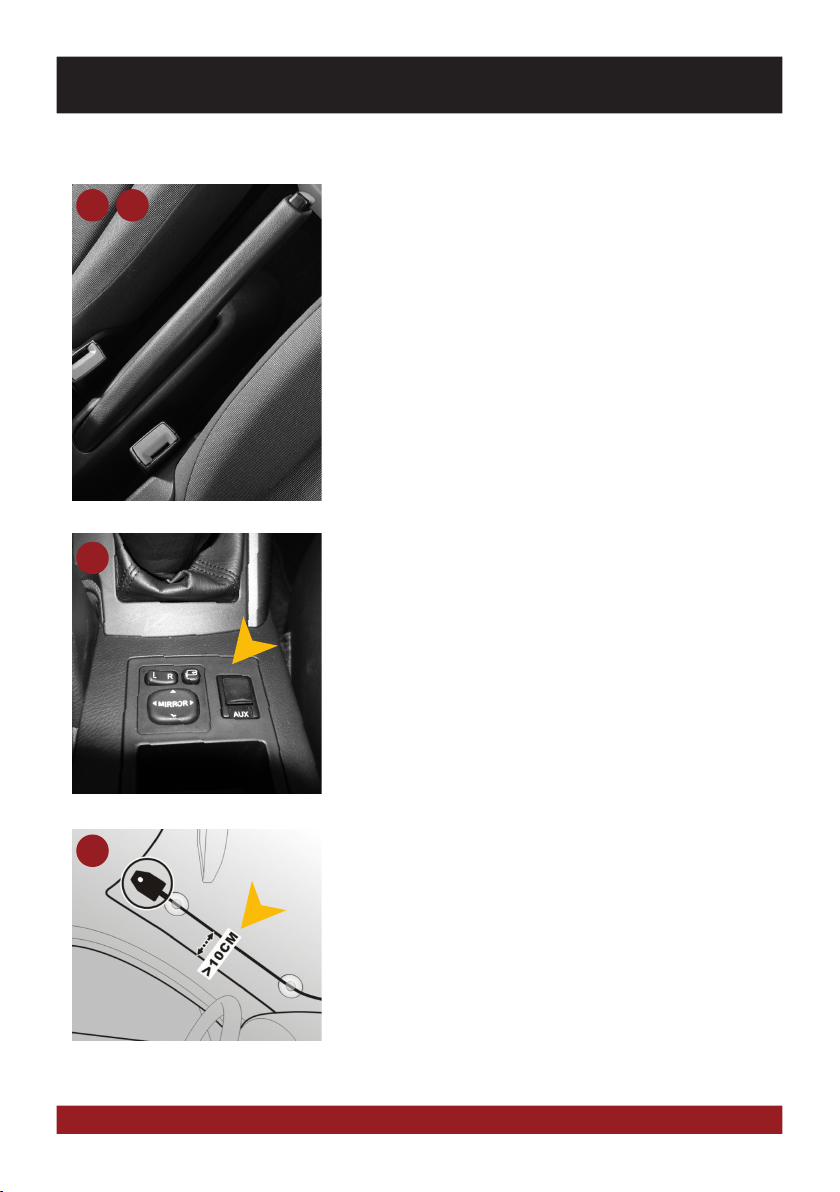
TMC cable antenna:
Connect the enclosed TMC antenna (17) with the USB port on and then lay
the antenna. For optimal reception it should be fastened to the windscreen
by using the suction cups, a hidden installation e.g. under the A-pillar or the
dashboard is also possible.
TMC Kabelantenne:
Schließen Sie die beiliegende TMC Antenne (17) an den USB Anschluss an und
verlegen Sie dann die Wurfantenne. Für optimalen Empfang kann diese an der
Scheibe mithilfe der Saugnäpfe befestigt werden, auch ein verstecktes Verle-
gen z.B. unter der A-Säule oder unter dem Armaturenbrett ist möglich.
17
AUX Port:
If your car is equipped with a factory USB port, the port is supported by the
device. Then use the cable set (15 instead 14), which is equipped with a car-
specific cable plug. Connect this plug with the original AUX-connector in the ra-
dio bay. If necessary, extend the hand brake cable. To select the AUX-Function
in the device tap „AUX“ in the Apps-Menu.
AUX Anschluss:
Sollte Ihr Fahrzeug über einen werksseitigen AUX-Anschluss verfügen, wird
dieser vom Gerät unterstützt. Verwenden Sie dann das Anschlusskabel (15
statt 14). Dieses ist mit einem fahrzeugspezifischen Stecker versehen. Schlie-
ßen Sie diesen an den originalen AUX-Stecker im Radioschacht an. Um die
AUX-Funktion im Gerät anzuwählen, tippen Sie „AUX“ im App-Menü.
15
15