EPS EPS-16 User manual

EDGE POWER SOLUTIONS 56VDC SERIES USER MANUAL VERSION 7 05/2020
USER MANUAL
EPS-16
EPS-32-V1
&
EPS-32-V2

Edge Power Solutions
EPS-32-V1 / EPS-32-V2 / EPS-16 Installation Manual Revision 7.0 05102020
Life-Support Policy
As a general policy, Edge Power Solutions does not recommend the use of any of its products in the following situations:
•Life-Support Applications where failure or malfunction of the Edge Power Solutions Product can be reasonably expected to
cause failure of the life-support device or significantly affect its safety or effectiveness.
•Direct patient care.
Edge Power Solutions will not knowingly sell its products for use in such applications unless it receives in writing assurances
satisfactory to Edge Power Solutions that:
•The risk of injury or damage have been minimized
•The customer assumes all such risks, and
•The liability of Edge Power Solutions is adequately protected under the circumstances.
The term life-support device includes but is not limited to neonatal oxygen analyzers, nerve stimulators (whether used for
anesthesia, pain relief or other purposes), auto-transfusion devices, blood pumps, defibrillators, arrhythmia detectors and alarms,
pacemakers, hemodialysis systems, peritoneal dialysis systems, neonatal ventilator incubators, ventilators (for adults or infants),
anesthesia, ventilators, infusion pumps, and any other devices designated as “critical” by the U.S. FDA
The information in this document has been carefully checked and is believed to be accurate. However, changes are made
periodically. These changes are incorporated in newer publication editions. Edge Power Solutions may improve and/or change
products described in this publication at any time. Due to continuing system improvements, Edge Power Solutions is not
responsible for inaccurate information which may appear in this manual. For the latest updates, consult the Edge Power Solutions
website at www.edgepowersolutions.net. In no event will Edge Power Solutions for direct, indirect, special, exemplary, incidental,
or consequential damages resulting from any defect or omission in this document, even if advised of the possibility of such damages.
In the interest of continued product development, Edge Power Solutions reserves the right to make improvements in this document
and the products it describes at any time, without notice or obligation.
Dangerous Voltage
This Symbol is intended to alert the user to the presence of un-insulated dangerous voltage within the products
enclosure that may be of sufficient magnitude to constitute a risk of electric shock to persons.
Multiple Power Inputs/Sources
This Symbol is intended to alert the user to the presence of more than one power input to the enclosure and
that all power inputs/sources should be disconnected prior to servicing of the unit.
Protective Grounding Terminal
This Symbol indicates a terminal that must be connected to earth ground prior to making any other
connections to the equipment.
Instruction
This symbol is intended to alert the user to the presence of important instructions in the
literature accompanying the device.

Edge Power Solutions
EPS-32-V1 / EPS-32-V2 / EPS-16 Installation Manual Revision 7.0 05102020
Table of Contents
SECTION 1:
•Introduction………………………………………………………………………………………….
•Quick Installation Checklist……………………………………………………………………
•Technical Support………………………………………………………………………………….
•Model EPS-32-V1………………………………………………………………..…………………
•Model EPS-32-V2………………………………………………………………………………….
•Model EPS-16……………………….………………………………………………………………
SECTION 2: Installation
•Standard Accessories……………………………………………………………………………
•Additional Required Items……………………………………………………………………
•Safety Precautions……………………………………………………………………………….
•Mounting PDU……………………………………………………………………………………..
•Attaching Safety Earth Ground Connection…………………………………………..
•Installing Phoenix Connectors………………………………………………………….……
•Connecting Output to Field Devices………………………………………………………
•Connecting to AC power Source……………………………...……………………………
•Connection to DC power source (Rack Mount)…………….………………………..
•Connection to DC power source (Wall Mount)…….……….………………………..
SECTION 3: Optional Integrated Fiber Optic Splitter
•Safety Precautions……………………………………………………………………………….
•Source Signal Connection(s)…………………………………………………………………
•Output Connections……………………………………………………………………………..
1
1
1
2
2
2
3
3
4
5
5
6
7
7
8
9
10
10
10

Edge Power Solutions
EPS-32-V1 / EPS-32-V2 / EPS-16 Installation Manual Revision 7.0 05102020
SECTION 1: Introduction
Edge Power Solutions rack mount power distribution units have been designed to provide +56VDC at up to 98W per output (See
Note 1) to low voltage DC devices such as:
•GPON Optical Network Terminals
•Distributed Antenna Systems
•LED Lighting
•CCTV
•Wireless Access Point
•Other applicable devices with similar input needs.
NOTE 1:
1. EPS-16
a. The maximum output per port is 98W
b. The maximum combined output for 120VAC input/or RMS Equivalent = 1400W
c. The maximum combined output for 208-240VAC input/or RMS Equivalent = 1600W
2. EPS-32-V1 (DUAL 15A INPUT)
a. The maximum output per individual port is 98W
b. The maximum combined output for 120VAC input/or RMS Equivalent = 2800W (1400W INPUT 1 + 1400W INPUT 2)
c. The maximum combined output for 208-240VAC input/or RMS Equivalent= 3200W (1600W INPUT 1 + 1600W
INPUT 2)
3. EPS-32-V2 (SINGLE 20A INPUT)
a. The maximum output per individual port is 98W
b. The maximum combined output for 120VAC input/ or RMS Equivalent = 1960W
c. The maximum combined output for 208-240VAC input/ or RMS Equivalent = 2800W Outputs
For Product Assistance or Technical Support call: 321-499-1919 - Option 4
1.1 Quick Installation Checklist
•The following steps are recommended to quickly install the EPS-RM-1x(xx)-100W-(s) Power Supply Unit for use.
a) Attach Rack Mount Brackets to the Power Supply Unit (Rack mount unit)
b) Mount the power supply unit in rack or wall location
c) Connect Safety Earth Ground connection to approved ground buss
d) Connect devices to output connections using properly sized wire. (12AWG-24AWG)
e) Connect to properly sized AC power source(s)
PAGE 1

Edge Power Solutions
EPS-32-V1 / EPS-32-V2 / EPS-16 Installation Manual Revision 7.0 05102020
1.2 Product Description
EPS-32-V1
•2RU 3.5” H x 16” D x 17” W
•26.2LBS
•(2) C19 Inputs – 5-15P
•(32) +56VDC Outputs (12AWG -24AWG) – (Up to 98W per output)
a) SEE NOTE 1 / PAGE 1
•(32) Resettable 1.75A Breaker (1 per output)
•Optional 1x32 or 2x32 Passive Fiber Optic Splitter
EPS-32-V2
•2RU 3.5” H x 16” D x 17” W
•26.2LBS
•(1) C19 Inputs – 5-20P
•(32) +56VDC Outputs (12AWG -24AWG) – (Up to 98W per output)
a) SEE NOTE 1 / PAGE 1
•(32) Resettable 1.75A Breaker (1 per output)
•Optional 1x32 or 2x32 Passive Fiber Optic Splitter
EPS-16:
•1RU 1.75” H x 16” D x 17” W
•16.6 LBS
•(1) 15A C19 Inputs
•(16) +56VDC Outputs (12AWG -24AWG) – (Up to 98W per output)
a) SEE NOTE 1 / PAGE 1
•(16) Resettable 1.75A Breaker (1 per output)
•Optional 1x16 Passive Fiber Optic Splitter
EPS-16-Wall Mount
•24” W x 24” L x 6.25”
•23lbs
•(1) 15A C19 Inputs / Option High Voltage DC Input
•(16) +56VDC Outputs (12AWG -24AWG) – (Up to 98W per output)
a) SEE NOTE 1 / PAGE 1
•(16) Resettable 1.75A Breaker (1 per output)
•Optional 1x16 Passive Fiber Optic Splitter
EPS-32-V1-WALL MOUNT / EPS-32-V2-WALL MOUNT
•24” W x 24” L x 6.25”
•23lbs / 26LBS
•(2) 15A C19 Inputs / (1) 20 C19 Input
•(32) +56VDC Outputs (12AWG -24AWG) – (Up to 98W per output)
a) SEE NOTE 1 / PAGE 1
•(16) Resettable 1.75A Breaker (1 per output)
•Optional 1x16 Passive Fiber Optic Splitter
PAGE 2

Edge Power Solutions
EPS-32-V1 / EPS-32-V2 / EPS-16 Installation Manual Revision 7.0 05102020
SECTION 2: Installation
2.1 Standard Accessories:
EPS-32-V1
•(2) 6’ C20 – 5-15P Power Cord (AC Version)
•(4) 16 Position Phoenix Connectors (Optional 2 Position Connectors Available)
•(1) Grounding Lug Kit
•(2) Rack Mounting Ears
EPS-32-V2
•(1) 6’ C20 – 5-20P Power Cord (AC Version)
•(4) 16 Position Phoenix Connectors (Optional 2 Position Connectors Available)
•(1) Grounding Lug Kit
•(2) Rack Mounting Ears
EPS-16
•(1) 6’ C20 – 5-15P Power Cord (AV Version)
•(2) 16 Position Phoenix Connectors
•(1) Grounding Lug Kit(Optional 2 Position Connectors Available)
•(2) Rack Mounting Ears
2.2 Additional Required Items:
•Small Tip Flat Head Screwdriver
•Phillips Head Screwdriver
•Appropriately sized ground wire
•Power Meter
PAGE 3

Edge Power Solutions
EPS-32-V1 / EPS-32-V2 / EPS-16 Installation Manual Revision 7.0 05102020
2.3 Safety Precautions:
PAGE 4
Only for installation and use in a Restricted Access Location in accordance with the following
instructions.
This equipment should only be installed by qualified personnel
Always disconnect the power supply cord(s) before servicing to avoid electrical shock. For products with 2 input
power cords, both must be disconnected before servicing.
Do not block venting holes when installing this product. Allow for maximum airflow at all times above,
below and each side of the unit.
WARNING: Earth Ground connection is essential before powering on device.

Edge Power Solutions
EPS-32-V1 / EPS-32-V2 / EPS-16 Installation Manual Revision 7.0 05102020
2.4 Attach Rack Mounting Brackets (rack mount units)
•Attach mounting brackets to each side of chassis with provided screws.
•Mount PDU into a properly secured wall mount, 2 post or 4 post rack.
•For wall mounting turn mounting brackets 90 degrees so that the mounting ear is flush with the bottom of the chassis.
oUnits should be mounted in a manner that allows for proper air intake and venting. Do not block the side or
top vent openings. When mounting in an enclosure or cabinet, the enclosure or cabinet should have a means
of ventilation in the form of side vents, open or perforated doors and or mechanical ventilation
methods. Allow at minimum 3” of clearance on each side of the unit and 1.75”(1RU) of clearance from the
top of the unit.
2.5 Chassis Grounding
•Attach properly sized ground wire as required and secure to an approved earth ground prior to making any other
connections to this device.
PAGE 5

Edge Power Solutions
EPS-32-V1 / EPS-32-V2 / EPS-16 Installation Manual Revision 7.0 05102020
2.6 Connecting Outputs to Field Devices:
2.6.1 Insert Phoenix Interface Connectors
•Insert 16 position male Phoenix connector into matching 16 position female Phoenix interface on front face of the
chassis
•The Connector will fit tightly into the interface. Tighten retainer screws with light torque if desired.
•If Connector removal is required use care to avoid bending the pins of the receiving connector.
2.6.2 Insert Optional 2 port Phoenix Connectors
•Insert optional 2 position male Phoenix connector into matching 16 position female Phoenix interface on front face of
the chassis.
•Observe proper polarity when terminating connector.
oWith the screw at the top the negative terminal is on the left the positive terminal is on the right.
•Fill in all unused positions with 2 position connectors to avoid leaving exposed pins
•If Connector removal is required use care to avoid bending the pins of the receiving connector.
PAGE 6

Edge Power Solutions
EPS-32-V1 / EPS-32-V2 / EPS-16 Installation Manual Revision 7.0 05102020
2.7 Connect Remote Device Power Cables
•Observing proper polarity, connect remote device power cables.
oAcceptable wire sizes: 12AWG – 24AWG
Choose appropriate AWG of wire based on Current, Distance & Acceptable Voltage Drop.
Consult with connecting device manufacturer for device requirements
oRecommended strip length: ¼”
•Tighten screw above input until cable is secure.
2.8 Connecting AC Power
SEE NOTE 1 / PAGE 1
•Connected provided cord to AC input on rear of chassis
oUnits can accept up to 240VAC with appropriate cable
•Push adjacent power switch(es) to the On/Reset Position when ready to power on unit and connected devices
oTurn on CB1 (EPS-16 & EPS-32-V2)
oTurn on CB1 & CB2 (EPS-32-V1)
•The power switch(es) will light up in off position to indicate the AC power source outlet is properly grounded.
PAGE 7

Edge Power Solutions
EPS-32-V1 / EPS-32-V2 / EPS-16 Installation Manual Revision 7.0 05102020
2.9 Connecting High Voltage DC Power
SEE NOTE 1 / PAGE 1
Rack Mount:
•Ensure DC power source is powered off and discharged.
•Utilizing provided locking cord kit connect the open lead end of cable to DC power source equipment
oWhite Lead to (-) Negative
oBlack Lead to (+) Positive
oGreen Lead to (GND) Ground
•Plug locking cables into the chassis inputs.
NOTE: Do NOT disconnect locking plugs until source power has been powered off and discharged.
PAGE 8
Edge Power Solutions
EPS-32-V1 / EPS-32-V2 / EPS-16 Installation Manual Revision 7.0 05102020
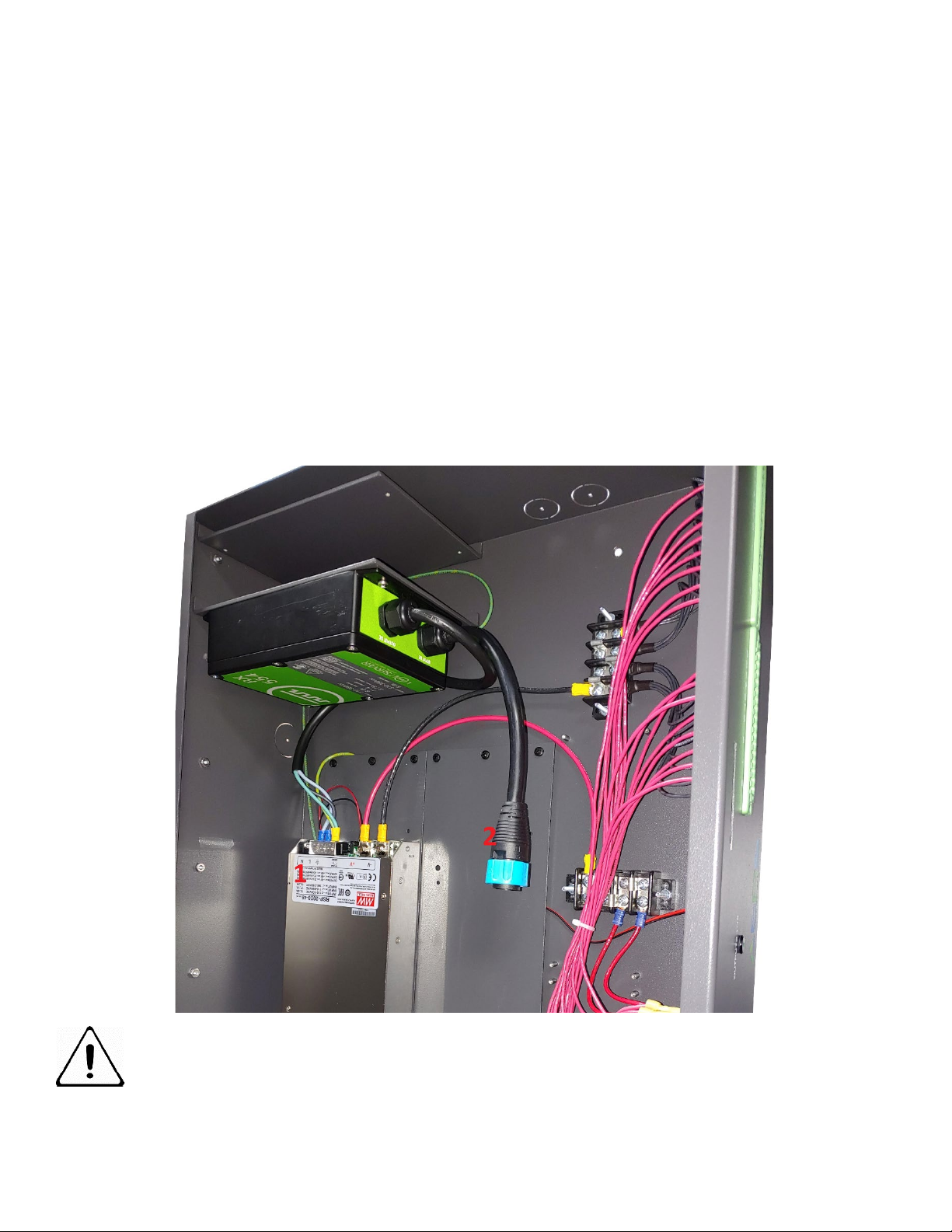
Wall Mount:
EPS wall mount systems may utilize locking plug system for external power connections or internal direct power supply connections
from an RMS equivalent DC power source or properly configured Digital Electricity™ receiver.
Direct Power Supply Connection: Connection Point #1 in illustration below
o(-) Negative Lead to Power Supply Neutral Input
o(+) Positive Lead to Power Supply Line Input
OPTIONAL Digital Electricity™ receiver connection: Connection Point #2 in illustration below
EPS wall mount PDUs have internal shelves for Digital Electricity™ receiver mounting. Follow Volt Server™ connection procedures.
Volt Server™ connection procedures take precedence over EPS instructions.
•DC Power out from receiver to PDU power supply connections:
o(-) Negative Lead to Power Supply Neutral Input
o(+) Positive Lead to Power Supply Line Input
•Receiver input connection from source transmitter:
oConnect pre-connected receiver input to mating input adapter tail via conduit knockout at the top, side, or bottom
of the enclosure.
NOTE: Do NOT disconnect until DC source power has been powered off and discharged.
PAGE 9

Edge Power Solutions
EPS-32-V1 / EPS-32-V2 / EPS-16 Installation Manual Revision 7.0 05102020
SECTION 3: Optional Integrated Fiber Optic Splitter
3.1 Optional Integrated Splitter Connection
3.1.1 Source Connection Input:
•Connect Input from active signal source equipment (GPON Port) using an SC/APC connector
•Patch other end to signal source equipment or connected fiber patch panel position.
3.1.2 Output Connection:
•Connect output from positions 1-32 on EPS-RM-1x32-100W-(s) or positions 1-16 on EPS-RM-1x16-100W-(S)
•Patch other end to servicing device or device servicing fiber patch panel position.
•On 16 Port Unit, Utilize included 1x2 splitter for 2x16 connection.
END
PAGE 10
WARNING:
Avoid eye exposure to fiber optic openings on this device when connected to external equipment in any
position. A fiber optic splitter is installed in this device. A connection to any position transmits invisible
laser light on all ports that could be damaging to the eye.
This manual suits for next models
2
Table of contents
Other EPS Power Supply manuals

EPS
EPS PSB 10000 4U User manual

EPS
EPS PSI 9000 2U Series User manual

EPS
EPS PSI 880-40R User manual

EPS
EPS NEXUS User manual

EPS
EPS BC 800 R Series User manual

EPS
EPS PS 880-170 R User manual

EPS
EPS PS 8016-20 DT User manual

EPS
EPS PSI 10000 4U User manual

EPS
EPS PSI 800 R Series User manual

EPS
EPS PSI 10000 4U User manual


