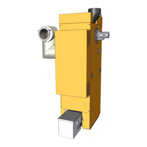
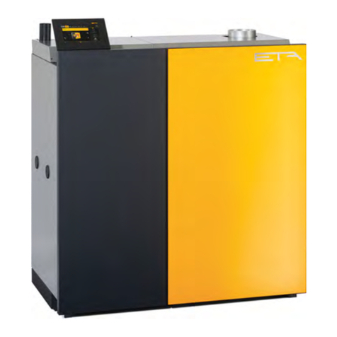
eta EEP 50 User manual

2017-10-04
EN
0000000234
V.009
X.35.4, X.39.1
93523-003 Precipitator
EEP 50, EEP 90, EEP 130
Operating Instructions

ETA Heiztechnik
Gewerbepark 1
A-4716 Hofkirchen an der Trattnach
Tel: +43 (0) 7734 / 22 88 -0
Fax: +43 (0) 7734 / 22 88 -22
www.eta.co.at

3
Contents
1 General . . . . . . . . . . . . . . . . . . . . . . . . . . . . . . . . . . . . . . . . . . . . . . . . . . . . . . . . . . . . . . . . . . . . . . . . . . . . . . 4
1.1 Preface. . . . . . . . . . . . . . . . . . . . . . . . . . . . . . . . . . . . . . . . . . . . . . . . . . . . . . . . . . . . . . . . . . . . . . . . . . 4
1.2 General information . . . . . . . . . . . . . . . . . . . . . . . . . . . . . . . . . . . . . . . . . . . . . . . . . . . . . . . . . . . . . . . . 4
1.3 Warranty, guarantee and liability . . . . . . . . . . . . . . . . . . . . . . . . . . . . . . . . . . . . . . . . . . . . . . . . . . . . . . 4
2 Technical data . . . . . . . . . . . . . . . . . . . . . . . . . . . . . . . . . . . . . . . . . . . . . . . . . . . . . . . . . . . . . . . . . . . . . . . . 6
3 Functional description. . . . . . . . . . . . . . . . . . . . . . . . . . . . . . . . . . . . . . . . . . . . . . . . . . . . . . . . . . . . . . . . . . 8
4 Safety . . . . . . . . . . . . . . . . . . . . . . . . . . . . . . . . . . . . . . . . . . . . . . . . . . . . . . . . . . . . . . . . . . . . . . . . . . . . . . . 9
4.1 General information . . . . . . . . . . . . . . . . . . . . . . . . . . . . . . . . . . . . . . . . . . . . . . . . . . . . . . . . . . . . . . . . 9
5 Installation . . . . . . . . . . . . . . . . . . . . . . . . . . . . . . . . . . . . . . . . . . . . . . . . . . . . . . . . . . . . . . . . . . . . . . . . . . 10
5.1 Prepare the boiler . . . . . . . . . . . . . . . . . . . . . . . . . . . . . . . . . . . . . . . . . . . . . . . . . . . . . . . . . . . . . . . . 10
5.2 Connect the precipitator with the boiler . . . . . . . . . . . . . . . . . . . . . . . . . . . . . . . . . . . . . . . . . . . . . . . . 11
5.3 Installing flue gas recirculation. . . . . . . . . . . . . . . . . . . . . . . . . . . . . . . . . . . . . . . . . . . . . . . . . . . . . . . 14
5.4 Concluding activities . . . . . . . . . . . . . . . . . . . . . . . . . . . . . . . . . . . . . . . . . . . . . . . . . . . . . . . . . . . . . . 16
6 Configuration . . . . . . . . . . . . . . . . . . . . . . . . . . . . . . . . . . . . . . . . . . . . . . . . . . . . . . . . . . . . . . . . . . . . . . . . 18
7 Electrical connections. . . . . . . . . . . . . . . . . . . . . . . . . . . . . . . . . . . . . . . . . . . . . . . . . . . . . . . . . . . . . . . . . 19
7.1 Requirements. . . . . . . . . . . . . . . . . . . . . . . . . . . . . . . . . . . . . . . . . . . . . . . . . . . . . . . . . . . . . . . . . . . . 19
7.2 Electrical connection . . . . . . . . . . . . . . . . . . . . . . . . . . . . . . . . . . . . . . . . . . . . . . . . . . . . . . . . . . . . . . 19
7.3 Circuit board EM-C3 . . . . . . . . . . . . . . . . . . . . . . . . . . . . . . . . . . . . . . . . . . . . . . . . . . . . . . . . . . . . . . 22
8 ETAtouch controller. . . . . . . . . . . . . . . . . . . . . . . . . . . . . . . . . . . . . . . . . . . . . . . . . . . . . . . . . . . . . . . . . . . 24
8.1 Function block [precipitator]. . . . . . . . . . . . . . . . . . . . . . . . . . . . . . . . . . . . . . . . . . . . . . . . . . . . . . . . . 24
8.1.1 Up to software version X.35.X . . . . . . . . . . . . . . . . . . . . . . . . . . . . . . . . . . . . . . . . . . . . . . . . . 24
8.1.2 Software version X.36.0 and later . . . . . . . . . . . . . . . . . . . . . . . . . . . . . . . . . . . . . . . . . . . . . . 24
9 Empty the ash box . . . . . . . . . . . . . . . . . . . . . . . . . . . . . . . . . . . . . . . . . . . . . . . . . . . . . . . . . . . . . . . . . . . . 25
10 Rectifying problems. . . . . . . . . . . . . . . . . . . . . . . . . . . . . . . . . . . . . . . . . . . . . . . . . . . . . . . . . . . . . . . . . . . 27
11 Dismantling, disposal . . . . . . . . . . . . . . . . . . . . . . . . . . . . . . . . . . . . . . . . . . . . . . . . . . . . . . . . . . . . . . . . . 29

4 www.eta.co.at
Preface General
1 General
1.1 Preface
Dear customer,
Safe and satisfactory operation of the product
depends, above all, on correct installation. In this user
manual, you can find out all the important installation
steps, information and instructions for this product
beforehand. Please take the time to look through it.
Warranty and guarantee
You should also read the "Conditions for warranty,
guarantee, liability" (see 1.3 "Warranty, guarantee and
liability") carefully. As a rule, these conditions will be
satisfied by a professional heating technician. Never-
theless, inform the technician of our warranty
conditions. All of the requirements we impose are
intended to prevent damage that neither you nor we
wish to occur.
Training the customer
To avoid errors in operation, please explain to your
customer exactly how his new product works and how
it should be operated and maintained.
Extended warranty
We grant an extended warranty if the product is com-
missioned by an authorised partner company or by our
own customer service. In this regard, please note the
warranty conditions applicable at the time of purchase.
Service agreement
You can ensure the best care for your heating system
by taking out a service agreement with one of our
certified contractors or our own customer service.
1.2 General information
Copyright
All contents of this document are property of ETA
Heiztechnik GmbH and are protected by copyright.
Any reproduction, transfer to third parties or use for
other purposes is prohibited without written permission
from the owner.
Software Description
The software version described in this documentation
corresponds to the version valid at the time of publica-
tion. The software version installed on your product
may differ from that described in this documentation.
A software update to a more recent version can
always be performed. With the appropriate au-
thorisation, the required files can be found at
"www.eta.co.at".
Subject to technical changes
We reserve the right to make technical modifications
without notice. Printing and typesetting errors or
changes of any kind made in the interim are not cause
for claims. Individual configurations depicted or
described here are only available optionally. In the
event of contradictions between individual documents
regarding delivery scope, the information in our current
price list applies.
Explanation of symbols
Instructions and information
Layout of safety instructions
SIGNAL WORD!
Type and source of danger
Possible effects
• Measures for avoiding the danger
Types of safety instruction
CAUTION!
On non-compliance with this safety instruction, there is
a risk of material damage.
WARNING!
On non-compliance with this safety instruction, there is
a risk of physical injury.
DANGER!
On non-compliance with this safety instruction, there is
a risk of major physical injury.
1.3 Warranty, guarantee and liability
Requirements
We can only accept liability for the function of our
products if they are correctly installed and operated.
This is only possible if the conditions below are
complied with.
General Warranty, guarantee and liability
5
Observe local building and fire safety regulations
Local building and fire safety regulations must be
observed.
Expanding the control system
Only components provided by us may be used for
expanding the control system, unless these are
generally available standard devices, such as thermo-
stats.
Regularly perform cleaning and maintenance
Cleaning and maintaining the product is essential. The
required steps andintervals are either containedin this
documentation or included as a separate document.
Repairs
Repairs are only permitted using spare parts provided
by us. The only exceptions are common standardised
parts such as electrical fuses or fastening materials, as
long as they possess the required features and do not
restrict the functionality of the system.
Proper installation
The installing contractor is liable for proper installation
according to the corresponding installation instructions
and the relevant rules and safety regulations. If you as
customer have installed the heating system partly or
entirely without relevant training and in particular
without up-to-date practical experience, without having
the installation checked by a trained and responsible
expert, we exclude defects in our delivery and conse-
quential damages resulting from this cause from our
warranty, guarantee and liability.
Repair of defects
For repairs of defects carried out by the customer orby
a third party, ETA shall only bear the costs or remain
obligated by warranty if this work was approved in
writing in advance by the customer service of ETA
Heiztechnik GmbH.
Surface corrosion
Surface corrosion on the inside of the precipitator is no
cause for concern. It does not impair the function.
Surface corrosion does not entitle to warranty or
guarantee claims.
Insulate the connecting pipe to the chimney
The connection between the boiler and the chimney
should be insulated with at least 30 mm, preferably 50
mm, of mineral wool to avoid thermal losses, which
can lead to a build-up of condensation.
Potential equalization is needed for the boiler
The boiler must be connected to the potential equaliza-
tion of the boiler room or the building. Country-specific
regulations must be observed.

6 www.eta.co.at
Technical data
2 Technical data
Precipitator installation
The illustrations show a precipitator for the wood chip boiler with a size of 1 (20-50 kW) and fuel discharge on
the left side. The flue gas recirculation shown is available optionally.
Boiler B H HFGR T1T2K E HR
20 - 50 kW 393 mm 1485 mm 1674 mm 952 mm 320 mm 150 mm 210 mm >2100 mm
63 - 90 kW 440 mm 1700 mm 1888 mm 1153 mm 320 mm 150 mm 210 mm >2500 mm
110 - 130 kW 440 mm 1760 mm 1947 mm 1767 mm 347 mm 180 mm 230 mm >2500 mm

Technical data
7
Precipitator Unit EEP 50 EEP 90 EEP 130
Weight kg 162 227 294
Ash box volume Litres 15 21 80
Electrical power consumption during operation (maximum
value/regular operation) W38 / 19 75 / 38 113 / 57
Electrical power consumption in ready mode W 1
Electrical connection
Voltage is supplied via the boiler 1 x 230 V / 50 Hz

8 www.eta.co.at
Functional description
3 Functional description
Precipitator function
The draught fan sucks the boiler flue gas through the
precipitator. It is deflected at its bottom and sucked
betweenthe innerwall andtheelectrodeto thefluegas
connection by the electrical field.
Fig. 3-1: Exhaust path
Inside the precipitator is the vertically oriented
"discharge electrode," which is connected to the
high voltage unit. The flue gas is cleaned as it flows
through the electrical field. In the electrical field (up to
30 kV voltage), the discharge electrode "pushes"
the dust particles from the flue gas to the inner wall of
the precipitator. The dust particles accumulate there
and the flue gas is cleaned as a result. Small quantities
of dust will remain adhered to the electrode. Therefore,
it is cleaned in regular intervals.
Fig. 3-2: Cleaning the discharge electrode
1 Striking weight
2 Shaft with gear
3Electrode
Deposits on the inner walls are removed by a sliding
rake which moves up and down. The sliding rake
operates at the same time as the de-ashing of the
boiler. The ash is transported on the bottom to the ash
box by an ash screw.
Fig. 3-3: Precipitator de-ashing
1 Sliding rake
2 Lever shaft for the sliding rake
3 Ash screw

Safety General information
9
4 Safety
4.1 General information
Operation only by trained personnel
The product may be operated by trained adults only.
Training may be provided by the heating technician or
our customer service. Please read the associated doc-
umentation carefully in order to avoid errors during
operation and maintenance.
Persons who lack experience and knowledge as well
as children may not operate, clean, or maintain the
product.
Storage of ash
The ash must be kept in non-flammable containers
with covers for cooling. Never put hot ash into the
waste bin!
DANGER!
Do not carry out work on high voltage units
The housing of the high voltage unit may
not be opened or damaged as there are
parts inside it that are under high voltage.
Non-compliance with the above may
result in serious or fatal injuries.
DANGER!
Caution high voltage!
The electrode inside the precipitator can
still have residual voltage even after
switching off the power supply.
Therefore, switch off the boiler at the
mains switch and ensure that it cannot be switched
back on before starting work. Then establish
additional earthing between the electrode on the
inside and the housing of the precipitator.

10 www.eta.co.at
Prepare the boiler Installation
5 Installation
Technical illustrations
The technical illustrations in this documentation
portray a size 1 (20-50 kW) wood chip boiler with the
fuel conveying system on the left side.
The illustrations are representative for all compatible
ETA boilers.
Assembly and installation only by qualified
specialist personnel
The assembly and installation may be performed
by specialist personnel with the corresponding
qualifications only.
5.1 Prepare the boiler
WARNING!
Switch off the electricity to the boiler via the mains
switch
Switch off the electricity to the boiler via the mains
switch. This prevents injuries caused by switching
the boiler on inadvertently.
Dismantle the draught fan and flue gas connection
from the boiler
Remove the panel from the top of the boiler.
Disconnect the plug of the connection line on the
draught fan. Remove the draught fan from the boiler
and carefully store.
Remove the temperature sensor from the flue gas
connection. Do not pull out the line, however.
Remove the flue gas connection from the boiler.

Installation Connect the precipitator with the boiler
11
If a flue gas recirculation is installed, the flue
ducts must also be removed from the flue gas re-
circulation.
To close the opening, mount the cover plate with the
seal supplied on the boiler.
5.2 Connect the precipitator with the
boiler
Place the precipitator
To place a size 1 or 2 precipitator (20 - 90 kW), mount
the carrying tube on both sides. In the case of a size 3
precipitator (110 - 130 kW), carefully lift with a
pallet jack.
Place the precipitator next to the boiler. The supplied
piping is suitable for placing the precipitator on the
opposite side of the fuel discharge. The required
clearances are found under 2 "Technical data".
If the precipitator is mounted to the left of the
boiler, the de-ashing drive motor must be rotated.
This is because 20-50 kW boilers have drive motors
which protrude over the panels.
Fig. 5-1: Rotate the drive
Inspect the horizontal alignment of the precipita-
tor and shim if necessary. Compensating shims
are included in the delivery scope. To inspect, remove
the cover on the top as well as the maintenance cover.
The electrode within is now visible. The

12 www.eta.co.at
Connect the precipitator with the boiler Installation
horizontal alignment is important, because equal
clearance of the electrode to the inner walls is required
on all sides.
Fig. 5-2: Check alignment
Fig. 5-3: Electrode
The precipitator can also be placed in another
location in exceptional cases. Contact us about
optimising the installation of the precipitator in this
regard. The piping between the boiler and precipitator
as well as the flue gas recirculation piping must be set
up separately.
If the boiler is placed on sound insulation mats,
the precipitator must also be placed on
sound insulation mats.
Install the draught fan and flue gas connection
Remove the panel from the top of the precipitator.
Evenly mount the draught fan with hexagonal screws
onto the precipitator.
A longer connection line for the draught fan
already protrudes from the precipitator. Plug it
into the draught fan and guide the other end over the
cable duct to the boiler. Remove the existing line
located there and clamp in the longer connection line
in its place.

Installation Connect the precipitator with the boiler
13
Fasten the flue gas connection with a new seal to the
precipitator.
Install piping for the flue gas
Install the flue pipe with hexagonal screws and a new
seal on the boiler.
Mount the flue pipe between the boiler and precipitator.
Seal all connectors with aluminium adhesive tape and
then attach with pipe clamps.
If the precipitator is installed on the opposite side,
the flue pipe must be shortened.
Attach the temperature sensor for the flue gas to the
connection in the connecting pipe.
Put the insulation over the flue pipe and attach
aluminium adhesive tape to the piles.
Route cables to the boiler
The cables for the power supply, CAN-Bus, earthing
and draught fan already protrude from the precipitator
panel. Route these cables to the boiler via the
cable duct.

14 www.eta.co.at
Installing flue gas recirculation Installation
Fasten the separate earthing cable (6 mm²) of
the precipitator to a nut on the boiler flue gas
connection using a lock washer.
Fig. 5-4: Earthing cable
WARNING!
Earthing of the boiler is required
Separate earthing is required for the boiler.
To do so, a connection must be established
between the boiler and the structural
potential equalisation in the boiler room
(minimum cross-section 6 mm²).
5.3 Installing flue gas recirculation
Mount flue gas recirculation
The following steps are only required if the boiler
is equipped with flue gas recirculation.
Before starting installation, dismantle the existing
piping for the flue gas recirculation on the back of the
boiler. Fasten the vertical flue pipe with the supplied
seal to the lower duct.
Fig. 5-5: Vertical flue pipe
Use a pipe clamp to mount the joint for the flue gas re-
circulation onto the precipitator. Only hand-tighten the
screws of the pipe clamp.
Fig. 5-6: Joint

Installation Installing flue gas recirculation
15
Connect the horizontal flue pipe with the flue pipe
already installed. Add a seal and only hand-tighten the
screws.
Fig. 5-7: Horizontal flue pipe
Fasten the horizontal line onto the flue gas connection
with a seal.
Evenly tighten all screws on the flue pipe and the
pipe clamp. If tensions are apparent, loosen the
screws and align the components with one another.
Put the insulation over the flue pipe and seal the piles
with aluminium adhesive tape.
Block the flue gas recirculation
The piping must be closed if the flue gas recirculation
is not needed. The required shut-off device is included
in the delivery scope.
Fig. 5-8: Flue gas recirculation shut-off device

16 www.eta.co.at
Concluding activities Installation
To block, remove the maintenance cover from the
joint. The seal remains, however.
Fig. 5-9: Maintenance cover
Press the flue gas recirculation shut-off device into the
joint and tighten evenly with the wing screws.
Fig. 5-10: Install the shut-off device
The flue gas recirculation function must be
deactivated in the control system of the boiler
after installing the shut-off device. See the boiler's
operating instructions.
5.4 Concluding activities
Attach the panels
Remove the panel from the top of the precipitator.
Attach the cover with self-tapping screws onto the
boiler.
Attach the ash box
Attach the ash box to the precipitator.

Installation Concluding activities
17
Connecting the flue pipe from the precipitator to
the chimney
The flue pipe (flue tube) from the precipitator to the
chimney must be connected on site. See the technical
data for the required dimensions; see chapter 2
"Technical data". Easily accessible cleaning openings
must be available in the flue pipe.
Establish earthing between the precipitator and
flue pipe to the chimney
Additional earthing should be established between the
precipitator and the flue pipe to the chimney (flue tube)
to prevent the flue tube from being charged.
A perforated tape that attaches to the precipitator flue
gas connection and the flue tube is best suited.
Fig. 5-11: Additional earthing
Insulate the connecting pipe to the chimney
The connection between the boiler and the chimney
should be insulated with at least 30 mm, preferably 50
mm, of mineral wool to avoid thermal losses, which
can lead to a build-up of condensation.

18 www.eta.co.at
Configuration
6 Configuration
Content of this configuration
Only the steps required for the configuration of this
product are described below. The configuration of the
complete heating system is described in the "Configu-
ration" manual supplied with the boiler.
Software version X.33.0 or later
The configuration requires software version X.33.0 or
later on the boiler.
An update must be performed first if an older version is
installed.
Starting the configuration assistant
The process of starting the configuration assistant
differs depending on the installed software version.
Software version X.35.X and earlier
• Increase the authorisation to [Service]. Then open
the [Toolbox] menu by pressing the button and
the [Configure system] button.
Software version X.36.0 and later
• In the system settings , increase the authoriza-
tion to [Service] and open the system configuration
menu with the [Systems configuration] button.
Start the configuration assistant with the
[Starting the assistant] button.
Description for software version X.36.0 and later
The following description and screen shots represent
the software interface of version X.36.0 and later.
Function block [Precip.] is already installed
The function block [Precip.] for controlling the precipi-
tator has already been installed at the factory. For
monitoring purposes, check whether this is shown in
the [Selected function blocks] column in the function
blocks overview.
If you have accidentally deleted the function
block and wish to reinsert it, contact ETA
Customer Service. As some parameters have to be
reset.
Adjusting options in the function block [Boiler]
To start up the precipitator, the option [Electro-
static precipitator] in the function block of the
boiler must be activated.
Select the required function block from the [Selected
function blocks] column:
Open the option and enable the following:
Press the [Accept] button to save.
Establishing a [Flue gas] connection
Establish a new connection by pressing the button
[New connection] and select the connection type [Flue
gas] The producers and consumers must be specified
for these; see the following table.
Further configuration and installation
Continue with configuration and installation ofthe
heating system as described in the "Configura-
tion" manual supplied with the boiler.
Selected function blocks
HA-C 0
Boiler
Electrostatic precipitator
Connections
Flue gas
Producers
HA-C 0: Boiler: Flue gas
Consumers
EM-C 8: Precip.: Flue gas

Electrical connections Requirements
19
7 Electrical connections
7.1 Requirements
Electrical connection must only be made by
qualified specialist personnel
The electrical installation must only be performed
by specialist personnel with the corresponding
qualifications.
DANGER!
Electric shock
There are live parts on the circuit boards. If
touched, they can cause injury and
property damage.
Before beginning any work, isolate the system
completely from all power sources, ensure that it
cannot be switched back on, and verify that it is
safely isolated from supply.
WARNING!
Earthing of the boiler is required
Separate earthing is required for the boiler.
To do so, a connection must be established
between the boiler and the structural
potential equalisation in the boiler room
(minimum cross-section 6 mm²).
DANGER!
Do not carry out work on high voltage units
The housing of the high voltage unit may
not be opened or damaged as there are
parts inside it that are under high voltage.
Non-compliance with the above may
result in serious or fatal injuries.
7.2 Electrical connection
Electrical connection to the boiler
Remove the plug from the terminal [S51] on the boiler
circuit board [HA-C]. Detach the wire on the plug [S53
STB] from the "COM" contact. It will be reattached to
the screw terminal later.

20 www.eta.co.at
Electrical connection Electrical connections
Guide the line from the precipitator to the circuit board
[HA-C]. Attach the 3 pole plug to [S51]. Attach the
individual wires (brown) to [S53] onthe "COM" contact.
Connect the previously disconnected 3 pole plug with
the 3 pole socket. Now attach the previously detached
wire from the "COM" contact to the screw terminal.
Also attach the CAN-Bus to the circuit board [HA-C], or
if it is occupied, to another open CAN-Bus terminal.
A terminal resistor (yellow jumper) must be set at
the end of the CAN-Bus . If both CAN-Bus
terminals are allocated, the terminal resistor must be
removed on this circuit board.
In the example listed above, the terminal resistor must
be removed from the circuit board [HA-C] at [X49].
Check the node numbers if the circuit boards are
the same design.
If multiple circuit boards of the same design (e.g.: 2x
EM-C) are connected to one another via CAN-bus, the
circuit boards of the same design must have serial
node numbers. In this way they are recognized in
CAN-bus and can be configured.
Other manuals for EEP 50
1
This manual suits for next models
2
Table of contents
Other eta Industrial Equipment manuals