Etaluma LS720 User manual


2
LS720 Microscope Manual 2021
Table of Contents
I.
Setting Up the LS Microscope
A. Items Included With Each LS720 Microscope
B. Optional Accessories (purchased separately)
C. Recommended Computer Specifications
D. Unpacking the LS Microscope
E. Removing the Shipping Lock
F. Connecting the Cables
G. Phase Contrast
H. Brightfield
I. Installing Objectives
J. About Lumaview
K. Downloading and Installing Lumaview
L. Connecting the LS720 Microscope
II.
Software: Getting Started with Lumaview
A. Starting Conditions
B. Launching Lumaview
C. Initialization and Calibration
D. Instrument Setup
E. Finding a Live Image With Manual Focus
F. Focusing
G. Snapping Images
H. Generating Auto Composite Images
I. Videos From Time-Lapse and Live Video
J. Setting Up Autofocus
K. Writing and Using Protocols
L. Creating a Z-Map
M. Editing a Z-Map
N. Tiling Across Locations
O. Live Video
P. Run Protocol
Q. Live Cell Imaging with LS720 Microscope in an Incubator
III.
Appendices
A. Removing Red Shipping Lock for LS720
B. Resolving Lumaview Driver Conflicts
C. Disinfecting the LS Microscope Before Placement into an Incubator
D. Setting up Windows 10 for Uninterrupted Time-Lapse

3
LS720 Microscope Manual 2021
This document is available for download at http://etaluma.com/products/downloads.
I.
SETTING UP THE LS720 MICROSCOPE
A.
Items Included With Each LS720 Microscope
■
Phase Contrast Accessory (Olympus)
•USB communication cable
•External power supply/cord with country-specific plug
•Hex wrench (3 mm) for removing/replacing shipping lock
•Fluorescence shroud (black microplate lid)
•Calibration 1536 well microplate
•Calibration 4x objective
B.
Optional Accessories (purchased separately)
•Labware Holders
■
Holder for 35 mm Petri dishes, fits inside Holder for 60 mm Petri dishes
■
Holder for 60 mm Petri dishes & Terasaki plates, SBS outer dimensions
■
Holder for microscope slides & 50 mm Petri dishes, SBS outer dimensions
■
Holder for 4 microscope slides in parallel, SBS outer dimensions
•Light Hood
•Lumaquant, image analysis software
•Microvolution, deconvolution software
C.
Recommended Computer Specifications
Windows 10; Core i7 or better processor; 500 GB to 1 TB SSD hard drive, 4 Gb minimum RAM(8 Gb
min. Lumaquant); single 4K monitor or two with 1080p HD resolution. Windows must have Service
Pack 2.0 with .NET version 4.5.2.
Microvolution deconvolution plugin for ImageJ/Fiji: A GPU is required; the most powerful NVidia chip
running CUDA that can be afforded is recommended for the best performance.

4
LS720 Microscope Manual 2021
D.
Unpacking the LS Microscope
1. Remove LS720 Microscope from the shipping box (save box and packing materials) and place
on a sturdy bench or counter.
2. If the LS Microscope will be used in an incubator or environmental chamber, it is recommended
that the initial setup be carried out on the bench under ambient conditions before placement
into the specialized environment.
E.
Removing the Shipping Lock
WARNING: You must remove red shipping lock before plugging the LS720
into power! If not removed, the LS720 will be damaged!
1. Using the supplied 3 mm hex wrench, loosen slightly the 2 set
screws on top of the installed shipping lock. Loosen slightly
the 2 set screws (smaller and more internal) on bottom of the
lock.
2. Unscrew completely the 2 larger 1-inch screws on bottom of the
shipping lock. Slide the shipping lock toward you to remove.
3. Keep the 4 set screws screwed into the shipping lock and place in
a secure place along with the two 1-inch screws and 3 mm hex
wrench.
WARNING: If packing the LS720 for shipment, you must install the red
shipping lock before placing into the shipping carton! If not installed, the
LS720 can be damaged! See Appendix A for instructions.
LS720 Shipping lock

5
LS720 Microscope Manual 2021
F.
Connecting the Cables
1. Connect the USB type B end to the LS720 at the rear left corner of the microscope. Wait to
connect the type A USB cable from the Microscope to the computer until Lumaview is installed.
2. Plug the external power supply/cord into the left side port (when viewing from the front)
and the plug into an AC outlet.
G.
Phase Contrast
a. Remove the Phase Contrast Accessory from its
shipping box. Attach Phase Accessory by placing the
holes on the bottom of the Phase Accessory bracket
over the pegs on the upper surface (right rear) of the
LS720. Make sure pegs are fully seated and arm is
totally flush with the LS720 surface. Tighten the large
thumb screw at the backof the Phase Accessory arm.
b. Connect the free end of the Phase Accessory power cable to the round socket nearby. This allows
the Phase Accessory to be controlled by Lumaview.
H.
Brightfield
1. Bright field imaging uses of the Phase Accessory with the included Slider in an open position
(no phase ring) and the iris adjusted for an optimum image in conjunction with a lowered
exposure and illumination level in Lumaview. Bright field images will be in gray scale due to
the monochromatic CMOS camera.
2. Overhead fluorescent lighting can cause uneven brightness including a striped pattern on the
image; if observed, move the LS Microscope or partially shade the light to reduce unevenness
across the sample.

6
LS720 Microscope Manual 2021
I.
Installing Objectives
1. Unscrew the deck knob at the front of the instrument until the top
deck releases and raise the top deck until it latches open. Unscrew the
black cap (or previously installed objective) on top of the optics block
and screw in the objective. Do not overtighten. To lower the top deck,
activate the release lever at the right rear hinge, lower the deck, and
tighten the deck knob.
2. When installing or changing an objective, carry out the insertion
quickly to minimize dust falling onto the mirrored dichroic filter. A
small amount of dust will not affect imaging. However, if dust is
significant and it appears to affect quality of the live image or snapped
images, contact Etaluma by email (support@etaluma.com).
J.
About Lumaview
1. The LS720 is controlled by the Lumaview software program. The latest Lumaview version is
downloadable from Etaluma’s website and must be installed prior to connecting your computer
for the first time.
2. Lumaview requires Windows 10. Desktop computers and laptops can be used, but the best
visualization correlates with monitor resolution equal to the sensor resolution (up to 1900x
1900 pixels). Note: The monitor does not affect image resolution unless the monitor is low
quality and affects your ability to judge focus.
The computer should have Windows .NET Framework 4.5.2 or higher installed; see
https://www.microsoft.com/en-us/download/details.aspx?id=25150 for more information.
If your computer does not have .NET Framework 4.5.2 or higher installed, downloading
Lumaview may automatically take you to the Microsoft .NET download page. Scroll down the
page to find the correctdownload. You can also download it directly from here:
https://www.microsoft.com/en-us/download/details.aspx?id=25150
This does not require a purchase.
Deck release lever

7
LS720 Microscope Manual 2021
K.
Downloading and Installing Lumaview
1. To download Lumaview, go to http://etaluma.com/products/downloads (under the Resources tab).
Click on Lumaview - ZIP link to start the download and save the folder when prompted. Go to your
downloads location and click to open the Lumaview.zip file.
Alternatively, the same Lumaview .zip file can be copied from the flash drive that comes with
the LS Microscope. Verify that this file is the latest version as posted on the Etaluma website.
2. If your computer has an older version of Lumaview, installing the newest Lumaview will over-
write the older versions. If there is a need to revert to an older version Lumaview, it will be
necessary to first uninstall the current version using the procedure described in Appendix B.
3. To install Lumaview, right click on the .zip file and Open with Windows Explorer.
Double click on the .msi installer file to start installation. If a Windows warning box about an
unrecognized App appears, click Run anyway.
You will be asked about the location; note that the default is a new Etaluma folder inside the
Program Files (x86) folder. During installation, a Device Driver Installation Wizard will open.
Click to continue (twice) and finish installing the two drivers. Installation of Lumaview will then
finish. After installation, a Lumaview shortcut (orange logo icon) convenient for launching the
software will be present on the desktop.
L.
Connecting the LS720 Microscope
1. If connecting to a computer that has been off, turn computer on. Make sure computer is connected
to its monitor(s). Insert the standard USB-A end of the supplied USB cable into a USB port on your
computer and the other square USB-B end into the square port on the rear left side. It is also
important to connect the Microscope directly to the computer USB port and not use a USB hub.
2. If Lumaview has not been run previously, it is important that the LS720 microcope and computer
be connected using the USB cable before launching Lumaview. This is because Windows needs to
load the USB drivers before Lumaview can run.
II.
SOFTWARE: GETTING STARTED WITH LUMAVIEW
The complete User Guide for Lumaview is in the Help Section after Lumaview is opened. Click on Help in
the Title Bar to open the pulldown menu, click Contents, or simply Click F1 to open the Help Section.

8
LS720 Microscope Manual 2021
A.
Starting Conditions
1. Lumaview has been downloaded and installed on the computer.
2. The microscope is connected to the computer via the USB cable.
3. Red shipping lock MUST be off, power cable is plugged into a standard AC outlet, and
fluorescence shroud is available if imaging involves fluorescence outside of an incubator.
B.
Launching Lumaview
1. Launch the Lumaview software from the desktop icon (or other chosen location) and allow the
microscope to be discovered and initialize. This may take a minute or so the first time.
Two windows will open on your monitor: Live Image Window inside the larger Main Window.
“Live Image Window” will be in the title bar when the Window is not maximized. When Live
Image Window is maximized, [Live Image Window] transfers to the end of the Main Window
title bar. The Live Image Window status bar at the bottom shows communication with the
camera sensor via continuous display of several useful metrics: current frame rate, data
transfer rate, number of frames collected thus far in the session, frame size, and session date
and time start.
Note: A variety of Windows configuration errors can be displayed
at this point. Please consult Appendix A.
2. The Live Image Windows includes a Left Toolbar with the following commands:
Select Channel, optimize settings
Move in XYZ
Snap Image
Composite
Video Record (toggles on and off)
Protocol
Zoom
Shortcut to Last Image file location
When Lumaview is open, the icon that resides in your computer dock appears as a document
with an arrow.
If the Left toolbar icons are too small, close Lumaview, right click the Lumaview shortcut icon
on the desktop and select Properties.

9
LS720 Microscope Manual 2021
1. Click on the "Compatibility" tab
2. Click the "Change high DPI settings" button near the bottom of the menu
3. Check the "Override high DPI scaling behavior" box and then select "System (Enhanced)"
right below it
4. Click "OK" to close the menus
Restart Lumaview.
C.
Initialization and Calibration
1. The LS720 automatically initializes every time Lumaview is started by moving the microplate
carrier to the Home position. The Home Position consists of the left front corner of the microplate
carrier frame being positioned over the objective and the objective retracted to the lowest Z level.
No image can be obtained at the Home position because it is under the microplate carrier frame.
2. If this is the first time the LS720 has been connected to the current computer, it is first necessary
to do a Calibration. Once completed, calibration is not needed again unless a different computer is
connected.
a. To calibrate the LS720, install the provided Calibration Motic EFN 4x
Objective. Place the provided Calibration 1536 well microplate into the
microplate carrier.
b. Click Utilities in the File Menu bar and in the drop-down menu click
Calibrate to open its dialog box. A communication dialog box will open
asking if a 4x objectivehas been installed. Click Yes and the communication
dialog box will close.
c. Note: if your Calibrate menu is offset similar to this:

10
LS720 Microscope Manual 2021
To fix this, right-click the Lumaview shortcut icon on the desktop and open ‘Properties’.
Under the ‘Compatibility’ tab, click on the button labeled “Change high DPI settings”.
At the bottom of the Lumaview.exe Properties panel that opens, look under “High DPI
Scaling override” and check the box labeled “Override high DPI scaling behavior. Scaling
Performed by System (Enhance).” Click ‘OK’ and re-launch Lumaview.
You may need to adjust your screen Scale to one below the Recommended in order to increase
the resolution of your display while running Lumaview.
d. The Live Image Window will now show red crosshairs, and the microplate
carrierwill move so well A1 is close to being over the objective.
e. Click the Manual Image icon in the left tool bar (top icon) to open its dialog box.
f. To use ambient light for calibration (recommended; see Section I.I.),
check Brightfield in Manual Image to activate Gain and Exposure sliders.
Start with Gain as low as possible and adjust Exposure until a mid-gray
tone is shown inthe Live Image Window.
g. If using the Phase Contrast Accessory for brightfield illumination (Section
I.I.) move the phase slider to an open position (without phase ring) and
move the phase condenser aperture (small lever on condenser ring)
Red crosshairs in
Live Image Window
and move the phase condenseraperture (small lever on condenser front
above slider) so only a low level of light is transmitted. In Manual Image,
check Brightfield, set Gain to 1.0, Illumination (%) low, and adjust Exposure
from zero until a mid-gray tone is seen in the Live Image Window.
h. In Calibration, move the Focus slider up while watching the Live Image
Window to detect when the well outline can be seen and is in sharp focus.
The Focus slider area becomes green whenever the Focus slider is active.
Using the X/Y Move arrows (and Step size arrows if needed), move the

11
LS720 Microscope Manual 2021
microplate carrier until the A1 well is centered in the Live Image Window.
Make sure the centered well is A1 by moving to the left and up to confirm it
is the corner well using the X/Y Move arrows, and then re-center the A1
well.
i. In Calibration, click Accept Calibration. The Calibration dialog box will now convert to the
Manual XYZ dialog box.
12
LS720 Microscope Manual 2021
j. Test the calibration on other wells by clicking the
Select Labware button in Manual XYZ to opens its
dialog box. (If Manual XYZ is not already open, click
itsicon in the left tool bar (second from top).
k. Click on Generic1536WellMicroplate.elf to highlight
it and then click OK. The appropriate Labware Map
dialog box (1536 well in this case) will open. Click
on any well and the microplate carrier will move to
center that well over the objective. Test the
microplate corners and other wells distant from
each other. If any wells are not centered, repeat the
Calibration procedure described in this Section.
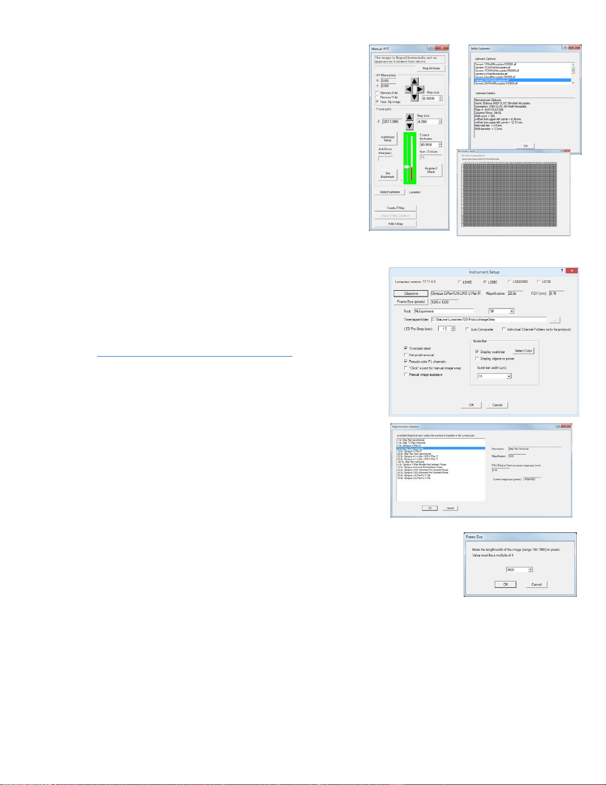
D.
Instrument Setup
1. Click on Configuration in the File Menu bar to open the drop-
downmenu and select Instrument Setup to open its dialog box.
2. Check the Lumaview version to make sure it is the most
recently posted version on the Etaluma website
(www.etaluma.com/products/downloads/). Ensure that
the correct model microscope being used is checked. If it is
necessary to change the LS Microscope model number that
is checked, you will be prompted to restart the program. Be
sure to restart so that all functions work correctly.
3. Click the Objective button to open its dialog box (called
Objective Lens Selection). Select the desired objective to
highlight it. Note that other fields about the objective and
image automatically fill based on magnification and a frame
size of 1200 x 1200 pixels. Click OK. Once selected, the same
information automatically fills in Instrument Setup.
4. Click the Frame Size button to open its dialog box. Using the pull-down menu,
select frame size desired. While the maximum is 1900 x 1900 pixels, the
default is set to 1600 x 1600 pixels. 1200 x 1200 should be a square within
the circular area of the objective while 1600 x 1600 will surround this area
showing some darkening in the corners. If faster frame rates are needed, use
smaller frame sizes, e.g., 200 x 200 pixels and decrease the Exposure.

13
LS720 Microscope Manual 2021
If the Frame Size is changed, there will be a prompt to restart
Lumaview. Click OK to close the prompt and then shut down
Lumaview. Upon restarting Lumaview, the frame size in the
lowerstatus bar will be the new size. If not restarted, the new
frame size may show in Instrument Setup but it may not actually
be different. Always check the lower left status bar of Live Image Window to see actual frame size.
5. Continue to review and adjust the various settings in Instrument Setup. For Root, enter desired
file name root for all images in this imaging session. Select the file format desired (Tiff is
recommended).
6. The Time-lapse folder path default is given but can be changed if desired. Time-lapse is set up
under Protocol as described below.
7. Select the time in seconds for each LED to be on before image snap. Recommended time for
fluorescence is 0.6 seconds (do not go below this time). Check Auto Composite to have images in
multiple channels automatically composited and saved in the Composites folder. Check Individual
Channel Folders to have images from multiple channels in a Protocol saved in separate folders
(e.g., for compiling time-lapse videos in single channels). Note: Auto composite may not produce
the optimal composite images and LumaQuant or third party compositing software may result in
better images.
8. Of the next 6 features listed on the left, check those desired:
a. Time/date label will be displayed in the lower left corner of each image.
b. Hot pixel removal. Check if desired and then complete Instrument Setup. (To start this
feature, click Utilities in the title bar and from the pull-down menu select Detect Hot Pixels
to open its dialog box. Information on next steps is available in the Help section.)
c. Pseudo color FL channels results in live and snapped fluorescent images colored with the
channel color and according to signal intensity.
d. “Click” sound for manual image snap results in a “camera-like shutter” sound whenever a
manual image is snapped.
e. Manual image autosave results in images being saved
automatically without the Save As dialog box opening each
time. When checked, each image is numbered according to
DOYHHMMSSmm where DOY is day of year, HH is hour in 24
hour time, MM is minutes, SS is seconds, and mm is milli-
seconds. Thus each image number is unique and in numerical
order.
Not checking Manual image autosave will result in the Save
As dialog box opening every time the camera icon is clicked
and the image has been snapped. In this case, the image file
name desired must be entered before clicking Save.
14
LS720 Microscope Manual 2021
9. On the right side of Instrument Setup, checking Display scale bar results in a scale bar in the lower
rightcorner of live and snapped images. If checked, click Select Color to choose color, check
Display objective power if desired, and select Scale bar width.
10. After all settings have been selected, be sure to click OK to save the
settings before exiting
Instrument Setup
.
E.
Finding a Live Image
1. Install the desired objective and sample labware. For labware that is
not SBS microplate footprint, use a labware holder such as the Multi-
Slide Holder for 1-4 microplate slides. Update Objective in Instrument
Setup as needed and click OK.
2. Click on the Manual Image icon in the Toolbar (top icon) to open its dialog
box. Click the Manual XYZ icon in the Toolbar (second icon from top) to
open its dialog box; Manual Image and ManualXYZ are used together to find
and focus on samples in the labware. If desired, move dialog boxes to the
sides of the Live Image Window. If closed and then reopened, they will
open in the same locations prior to closing. However, when Lumaview is
closed, the dialog box positions will not be saved.
3. Note, following initialization, the objective will be under the frame of the
nest and is not an imaging location. Select a desired XY location in a sample
labware using one of two options in Manual XYZ:
a. Use the X/Y Move arrows (and Step size arrows if needed) to move to
different locations or wells in the sample labware, or
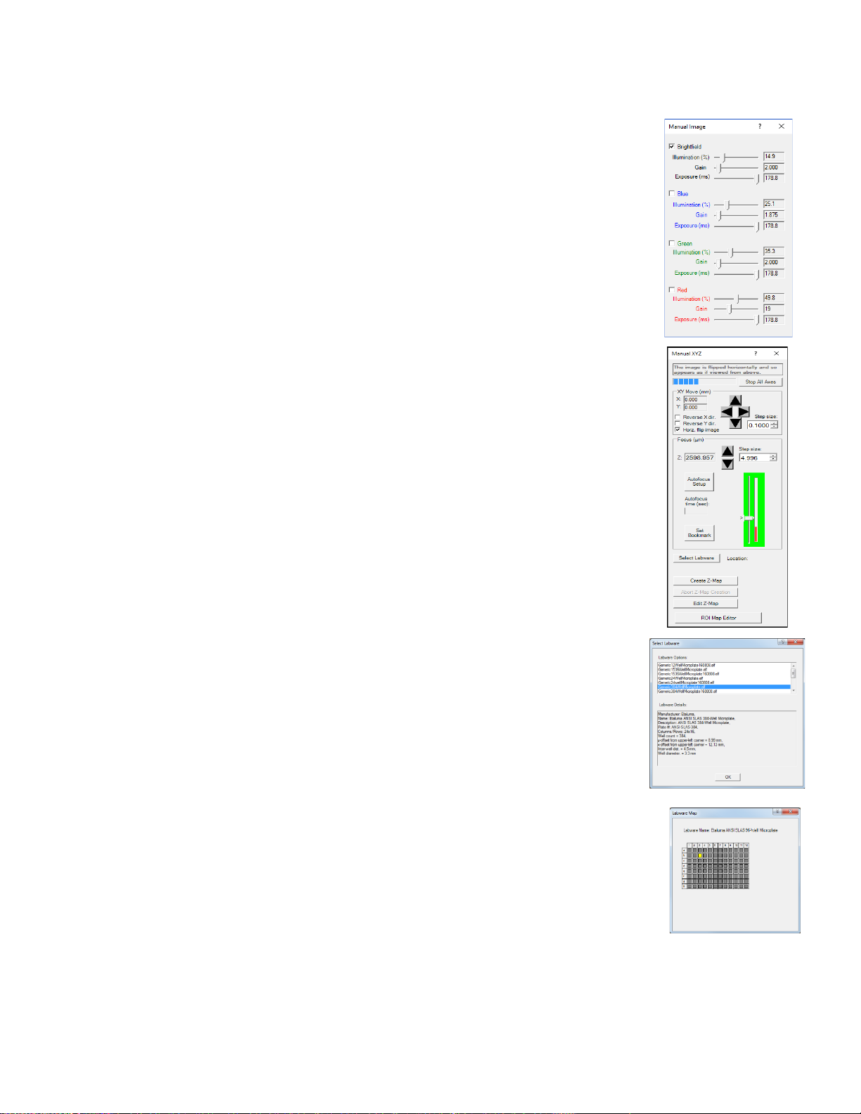
b. Click on Select Labware to open its dialog box. Click on the labware
type desired to highlight it and click OK. The appropriate Labware
Map will then open. Click on a location and the microplate carrier will
move so the location is centered over the objective. For further
movement from the location, use the X/Y Move arrows (and Step size
arrows if needed) in Manual XYZ. Clicking again on the original
location in Labware Map will re-center on that location.
c. Image orientation: The live image displayed on the monitor is as
viewed from the bottom as for all inverted microscopes. To see the
live image asviewed from the top, check Horz. Flip image in Manual
XYZ. However, allimages are captured as viewed from the bottom.
d. XY movement: In Manual XYZ, when a directional arrow in XY Move is
clicked, the live image on the monitor moves in that direction. However,
the labware moves in the opposite direction in order to place the new
location over the objective. For example, to image a location to the right of
the current location, the labware must move to the left for the new location
to be over the objective. To have the live image and labware move in the
same direction, check either or both Reverse X dir And Reverse Y dir.
This feature is particularly helpful when moving across labware, e.g, going
well to well in a microplate

15
LS720 Microscope Manual 2021
4. In Manual Image, select the channel(s) to use. For fluorescence, the included Shroud (or other
protection from light) must be placed over the labware. Start with Exposure at maximum and Gain
a low as possible. Increase Illumination gradually to the desired brightness. For dim samples, if
Illumination is at maximum, increasing the Gain can be used to increase signal but it will also
increase the background.
5. For transmitted imaging, check Brightfield in Manual Image and move the phase condenser iris
lever on the front of the phase illuminator so only a low level of light is transmitted. Set Gain to
minimum, Illumination (%) to 10-20%, and adjust Exposure downward until a mid-gray tone is
seen in Live Image Window.
6. For phase contrast using the Phase Contrast Accessory, position the slider in the center position,
check Brightfield in the Manual Image menu and move the phase condenser iris (on front of
condenser) to the left to the fully open position.
F.
Manual Focusing
1. In Manual XYZ, move the Focus slider up while watching the Live Image Window to
detect the sample coming into focus. The Focus slider area becomes green
whenever the Focus slider is active. Clicking on the slider vertical line above or
below the current focus level causes the focus level to jump up or down,
respectively, by 100 um. Continue to adjust the focus using the Focus Z up and
down arrows (and Step size adjustments if needed) until a sharp image is
achieved. Adjust Illumination and Gain settings in Manual Image during the focus
process as needed. Click the Set Bookmark button to record the focus level for an
easier return to this level.
2. To facilitate the focusing process, click on the Zoom icon on the Left Tool Bar. The
Zoom feature toggles between displaying the entire image fitted to the Live Image
Window and displaying the image matched 1:1 with the monitor resolution (pixel:
pixel). If the monitor resolution in pixels is less than the frame size, which is typical,
the image will be enlarged (zoomed). The Live Image Window will now show a
center portion of the entire image. Click the Zoom icon again to fit the image to the
Live Image Window.
3. If necessary, adjust Illumination and/or Gain as needed.
4. When focus is found it can be useful to set the bookmark for locating the focus level quickly again.
G.
Create Z-Map
This will perform an autofocus on all wells of a plate and remember those z-values in a Z-map file.
H.
Snapping Images
1. When the desired field has been illuminated and focused in Live Image Window, click the Camera
icon in the Left Tool Bar (third from the top) to snap the image. If the Zoom function was used to
focus, the image captured will include the entire field of view (FOV) observable with the Zoom off.
2. If Manual image autosave was checked in Instrument Setup, images will be saved automatically
using the time-based numbering system. If Manual image autosave was not checked, a Save As

16
LS720 Microscope Manual 2021
dialog box will open after the image was snapped. Images will be saved in the Etaluma folder
formed automatically whenever Lumaview is downloaded and installed.
3. Images are captured and saved as seen by the camera, i.e., from the bottom. If desired, images can be
flipped horizontally to show how they would appear from the top. To accomplish this,check “Horz
flip image” in the Manual XYZ dialog box. The message “The image is flipped horizontally and so
appears as if viewed from above” is then displayed at the top of the dialog box.
4. To view the last image snapped, click the Folder icon in the Left Tool Bar (bottom icon) to
launchWindows Explorer and open the most recently used Destination Folder.
I.
Auto-Generation of Single Fluorescence Composite Images
1. Click the Composite icon in the Left Tool Bar (fourth from the top) to open its dialog box. Check the
channels desired. To use values optimized previously in Manual Image, click Use Manual Settings to
upload the settings. Values can also be entered manually.
a. Click OK to start the snapping of individual images in progression. Each LED will turn on for
thepre-snap interval and then flash when the image is snapped. If “Click” sound for manual
imagesnap was checked in Instrument Setup, the shutter-like sound will be heard for each
image.
b. The fluorescence composite image will appear automatically in the Main Window matched
1:1 with the monitor resolution (pixel:pixel) and with its Title Bar showing the full path
where it is located.
2. Composites including the transmitted channel (phase contrast or brightfield)
a. In Instrument Setup, make sure Auto Composite is checked.
b. We will use a very short Protocol in order to construct a composite which includes the
transmitted channel. Configure a Protocol with the channels desired. In the Acquisition tab,
select Time-Lapse and set both Interval and Duration to 1 sec. Click Run and after the images
are snapped, click the Last File icon in the Left Tool Bar (lowest icon). The folder containing
the Composite image will open.
J.
Live Video (Manual)
1. When a desired field has been illuminated and focused in Live Image Window, click the Video
Record icon in the Left Tool Bar (fifth from the top) to open its dialog box. Select parameters
requested and also those in Instrument Setup such as file format. Images captured will be saved to
the Video folder inside the Manual folder.
2. Click OK and image capture will begin. To stop image capture, click the Record Video icon in the
Left Tool Bar again and it will report the number of frames recorded.

17
LS720 Microscope Manual 2021
K.
Manual Setting Up Autofocus
The autofocus algorithm scans through the requested focus Range with a
coarse and then finer z axis step size monitoring contrast and finding its
maximum. It starts at the lowest value in the Range and begins stepping
upwards at an initial step size dependent on the objective installed.
Calculations of the contrast are made at each level until the upper limit of the
Range is reached.
The algorithm then moves the focus to the position of the maximum contrast
and a new range, 20% size of the original Range, is defined and centered on this
rough maximum contrast. A new scan is initiated from the bottom of the new
Range with a new step size which is 1/3 of the previous step size.
Again, the algorithm moves to the position of the maximum contrast and a new
range that is 20% of the last range is defined, again centered on the previous
maximum contrast. A final scan is initiated from the bottom of this most recent
range with the minimum z-axis step size defined for that objective used.
Finally, the algorithm determines the maximum contrast level from the smallest
Range and finest step size and moves the z-axis to that position.
If the algorithm reaches the Timeout before converging on a focus, the
algorithm will terminate and move the z-axis corresponding to the highest
contrast value it found up to that point.
The autofocus set up allows a Center, Range, and Max Focus Time to be set.
The Center value is the expected focus, often determined manually. The expected focus in different
locations can be different. It is best to make the Center equal to the average focus in the sample locations
unless using a Z-Map or ROI Map where the z coordinate acts as the Center.
The Range should be set in accordance with the variation in the average focus across multiple positions,
with a minimum range based on the objective magnification (see Table 1). The highest and lowest
expected focus level should be comfortably within the Range with respect to the Center. If Autofocus is
unreliable, increase the Range until it becomes reliable.
Max Focus Time is the time before it chooses the best focus it has found. This is set to 15 seconds by
default but often good AF can be achieved in under 5 seconds with optimization of the Center and Range.
You should decrease this time until it becomes unreliable and fails to auto focus.
1. Use Manual Image and Manual XYZ to find a focused live image in a desired XY
position. In Manual XYZ, click the Autofocus Setup button to open its dialog box.
2. Transfer the manually determined Focus Z level in Manual XYZ to the Center
positionfield of Autofocus Setup. The Focus range will be set to a default value of
200 um. Change this to the recommended Minimum Range for each objective
magnification according to the following table:

18
LS720 Microscope Manual 2021
3. The Max focus time will be set to the default of 15 sec. This can be reduced as performance of the
autofocus is confirmed. The Max focus time should be at least that required for successful
autofocus but optimally only a few seconds longer. Autofocus of 3 seconds should be possible in
flat labware with 2D samples.
4. Click OK and autofocus will occur. The Focus Z level in Manual XYZ will now be updated to the
new autofocused Z level. The actual time taken to reach autofocus, i.e., the Auto focus time (sec),
will also be shown.
5. If autofocus did not result in a sharp live image, make sure the Center position transferred was
correct. In general, if autofocus consistently uses the full Max focus time, the range is too great for
the time entered or the time is insufficient. It may be necessary to decrease the Focus range
and/or increase the Max focus time.
6. Upon successful autofocus, move to other locations distant from the initial location. Click Select
Labware in Manual XYZ and the appropriate Labware Map will open (see Section II.E.3. above).
Select a location and repeat Steps 1-4 above.
7. Continue to move to other locations far away from the initial ones and repeat autofocus. It may be
necessary to re-enter the Center position and/or adjust the range. To determine the final
parameters,review the upper and lower Z levels obtained and use the approximate mean for the
Center position. For the range, determine the spread between the highest and lowest expected Z
values and make sure the Range contains those values comfortably.
Magnifi-
cation
Numerical
Aperture
Depth of
Field
(µm)
AutoFocus
Minimum Step
Size (µm)
AutoFocus
Maximum
Step Size
(µm)
Minimum
Range
(µm)
Recommended
Z-Slice Step Size
(½ DoF) (µm)
4x
0.10
55.5
20
72
100
27.75
10x
0.25
8.5
8
36
50
4.25
20x
0.40
5.8
2
18
25
2.9
40x
0.65
1.0
1
9
15
0.5
60x
0.85
0.40
0.5
6
10
0.2
100x
0.95
0.19
0.2
4
10
0.11

19
LS720 Microscope Manual 2021
A.
Creating a Z-Map
1. Load desired labware with samples into labware carrier.
2. Find a Live Image in a location as described in Section II.E.
above.
3. Set up Autofocus using steps in Section II.J. above.
4. In Manual XYZ, click the Create Z-Map button near the bottom. The
Select Labware dialog box will open. Click on the labware type desired
to highlight it and then click OK.
5. A Z-Mapping instruction dialog box will now open. Click Yes.
6. The Choose Name for the Z-Map File dialog box will now
open. Choose the Filename for your Z-Map file and click OK.
7. The Z-Map Selection dialog box will now open. Select
the locations in the labware to be Z-Mapped. Locations can be
selected by clicking on them individually,clicking on the name of
any row (A, B, etc) or column (1, 2, etc), or clicking on Select All.
8. Click OK and Z-Mapping will begin.
B.
Editing a Z-Map
1. In Manual XYZ, click the Edit Z-Map button at the bottom to
open its dialog box. Select the Z-Map File to be edited.
2 Locations that were Z-Mapped become shaded in yellow. Click
on any Z-Mapped location and the Edit Z-Map Well dialog box
for that location will open. Click the up and downarrows to
manually change the focus. This allows both review of the Z-
Map value and making a change if desired.
3. In Manual XYZ, click the Edit Z-Map button at the bottom to open its dialog box.
Select the Z-Map File to be edited.
4. Review the Z-Map and make changes if desired. Click OK to return to Edit Z-Map. Click Cancel
to keep the Z-Map value as it was before. Click on other locations to check and/or change their
Z-map values. Be sure to click OK to save anychanges before leaving Edit Z-Map.

20
LS720 Microscope Manual 2021
C.
ROI Map Editor
1.
Clicking the ROI Map Editor will open a menu that allows the recording of XYZ positions of
interest
Add will record the current location in the table. Delete will remove the highlighted position.
Insert will place the current location above the highlighted location. Move stage to Selected
Coords will go to the location highlighted. The ID field can be edited with simple text. Using an
ROI Map in the Protocol XYZ tab will look like this:
D.
Writing and Using Protocols
1. To configure an automated microscopy run, including time-lapse, the Protocol feature is utilized.
Click the “P” icon in the Tool Bar.
Other manuals for LS720
1
Table of contents
Other Etaluma Microscope manuals


