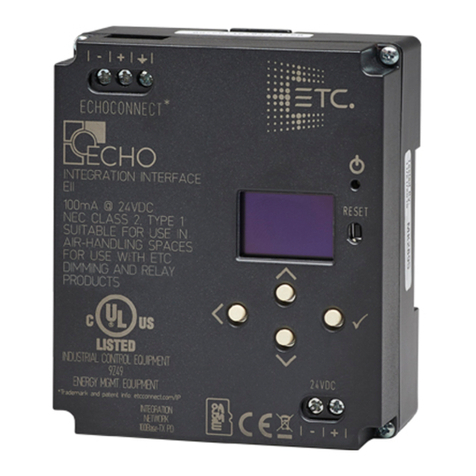
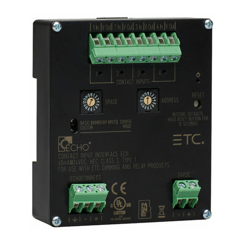
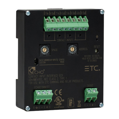
ETC Echo-Echoflex Interface User manual

ETC Installation Guide
Unison Echo®-Echoflex Interface
Corporate Headquarters
Middleton, WI, USA
Tel +608 831 4116
London, UK
Tel +44 (0)20 8896 1000
Service: (UK)
Rome, IT
Tel +39 (06) 32 111 683
Holzkirchen, DE
Tel +49 (80 24) 47 00-0
Service: (DE) techserv-hoki@etcconnect.com
Hong Kong
Tel +852 2799 1220
Web: etcconnect.com
© 2017 Electronic Theatre Controls, Inc.
Product information and specifications subject to change. ETC intends this document to be provided in its entirety.
7186M2103
Rev B
Released 2017-10
Overview
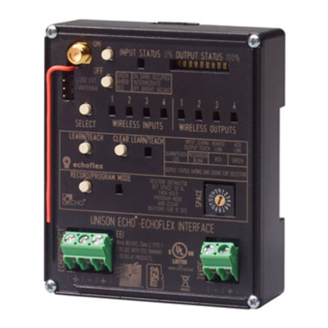
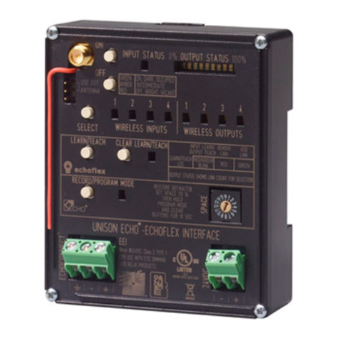
The Echo-Echoflex Interface (EEI) provides communication
between Unison Echo and Echoflex control systems by
converting wireless Echoflex controls into Unison Echo
actions, and enabling Unison Echo controls to control
wireless Echoflex power controllers.
The Echo-Echoflex Interface installs on standard DIN rail.
Accessory Kits
ETC provides a Low Voltage DIN rail Cover Kit (ETC part
number 7186A1218) that allows installation of the Echo-
Echoflex Interface to any standard 4” (10.16cm) junction box
(provided by others). Contact ETC for ordering details.
ETC offers an Echo-Echoflex Interface Antenna Kit (ETC part
number 7186K1001) that allows the installation of an external antenna. Contact ETC for ordering details.
Specification
For use with ETC dimming and relay products (902 MHz radio products only).
Ambient Environment
For indoor use only. Supports plenum rating.
• Operating temperature 0-50°C, 5-95% non-condensing humidity.
Electrical Specification
The EEI requires 24 Vdc (Class 2) power, supplied by an external 24 Vdc power supply. Termination for this
connection is provided on a two position terminal, labeled 24 Vdc, accepting 26-14 AWG (0.4 - 1.6 mm2)
wires, typically a 16 AWG (1.5 mm2) black and red wire pair.
Data and Wireless Signal
In addition to 24 Vdc, the Echo-Echoflex Interface requires EchoConnect™, which is Belden 8471 (or
equivalent) plus one ESD ground wire, supporting data and control to the Echo connect station bus.
Reference
Electrical Specification
for more information about powering the Echo-Echoflex Interface.
For communication with other wireless Echoflex devices, the Echo-Echoflex Interface includes a built-in
902 MHz radio. Communication is possible between the Echo-Echoflex Interface and other Echoflex
wireless devices that also support 902 MHz radio communication.
Note:
Installation should follow all local codes and standard electrical practices.
Note:
NEC Class 2 product are to be wired in accordance with NEC Article 725 and local
jurisdiction requirements.
All power and control wiring should be installed and terminated by a qualified installer
and should follow standard wiring installation practices.

ETC Installation Guide
Echo-Echoflex Interface
Echo-Echoflex Interface Page 2 of 15 ETC
Compliance
UL and cUL Listed, UL2043 listed for installation and use in a plenum space.
RoHS compliant
WEEE marked
FCC: Contains FCC ID: SZV_STM300U - the enclosed device complies with Part 15 of the FCCRules.
Operation is subject to the following two conditions: (i.) this device may not cause harmful interference and
(ii.) this device must accept any interference received, including interference that may cause undesired
operation.
Contains IC: 5713A-STM300U / Contient le module d´émission IC: 5713A-STM300U
Range Planning
The EEI interfaces Unison Echo communications with Echoflex controls using a 902 MHz wireless signal. For
best wireless performance, because radio waves can be susceptible to interference, some basic principles
should be followed when determining the location of the EEI to the Echoflex wireless stations and
controllers.
Additionally, ETC requires that the total combined length of an EchoConnect data run (using Belden 8471
or equivalent) must not exceed 1,640 feet (500 m). This requirement should be considered when
determining the location of the Echo-Echoflex Interface for installation.
Range Planning Guidelines for Wireless
When an event is triggered by a button station or sensor, a wireless message is sent between the EEI and
the linked Echoflex device(s). Radio signals become inherently weaker the further they travel and coverage
can be decreased by certain materials or obstacles between the stations and controllers. Although the
wireless signal can transmit through walls, they are dampened more than on a direct line-of-sight path.
Line-of-sight is always the best application when possible.
Typical Radio Range
Material Range - Typical
Line of sight 80 feet (24 m) corridors
Line of sight 330 feet (100 m) open halls
Plasterboard 80 feet (24 m) through 5 walls
Brick 33 feet (10 m) through 3 walls
Concrete 33 feet (10 m) through 3 walls
FerroConcrete 33 feet (10 m)
Ceiling 1 drop ceiling (drywall not
recommended)
Signal Loss
Material Attenuation
Wood/Plaster/Glass 0-10%
Brick/MDF 5-35%
Metal 90-100%

ETC Installation Guide
Echo-Echoflex Interface
Echo-Echoflex Interface Page 3 of 15 ETC
Installation
Install Interface to DIN rail
1: Ensure the section of DIN rail to be used is mounted
securely according to the manufacturers requirements.
DIN rail is provided by others.
2: Hook the bottom of the EEI under the lower DIN rail as
shown.
3: Pivot the device up and depress until the top clip on the
device seats to the top rail.
Connect Wiring
Connect EchoConnect
EchoConnect terminations require Belden 8471 (or equivalent)
between the EchoConnect station bus and Echo-Echoflex Interface, plus one 14 AWG (2.5 mm2) ESD
ground wire.
1: Strip 3/8” (9-10 mm) of insulation from the bare end of the Belden 8471 (or equivalent) wires and
the ESD ground wire.
2: Loosen the three screw terminals on the EchoConnect terminals.
3: Insert the data + wire (white is typical) into terminal 3 (identified with a + symbol), insert the data -
wire (black is typical) into terminal 2 (identified with a - symbol), and insert the ground wire (green/
yellow is typical) into terminal 1 (identified with a ground symbol).
4: Secure the screws firmly onto each wire.
Connect 24 Vdc
An external 24 Vdc (Class 2) power supply is required to power the EEI. Terminate to the interface terminals
labeled 24 Vdc. Terminals accepts 26-14 AWG (0.4 - 1.6 mm2) wires (typically a 16 AWG black and red wire
pair).
1: Strip 3/8” (9-10 mm) of insulation from the bare end of each 16 AWG (1.5 mm2) wire.
2: Loosen the two screw terminals on the 24 Vdc terminals.
3: Insert the “negative -” wire (black wire typical) into terminal 1 (identified with a - symbol), and insert
the “positive +” wire (red wire typical) into terminal 2 (identified with a + symbol) of the 24 Vdc
terminals.
4: Secure the screws firmly onto each wire.
Connect External Antenna (optional)
An external antenna can be used with the EEI.
1: Connect the EEI antenna to the RF jack.
2: Move the jumper located below the RF jack to the “Use Ext. Antenna” position.
2
3

ETC Installation Guide
Echo-Echoflex Interface
Echo-Echoflex Interface Page 4 of 15 ETC
Set Space
The EEI participates in an Unison Echo Control system using the configured Space, which is selectable using
the rotary switch on the front of the unit. Set the Space rotary switch to the desired Space number for this
controller. All devices that are in the same Space will share control of the connected Unison Echo stations
and sensors.
Power Up and Operation
Once the EEI is connected to the EchoConnect station bus and power is applied, the unit’s Wireless Input
1 LED will illuminate, indicating its ready for operation.
Echoflex System
Up to 35 compatible 902 MHz wireless Echoflex devices can be linked to the EEI through its inputs and
outputs.
When linked to the interface’s Wireless Echoflex Inputs, Echoflex devices can control Unison Echo presets
and space levels. Compatible Echoflex wireless control devices can be configured for input control.
When linked to the interface’s Wireless Echoflex Outputs, Echoflex wireless power controllers are controlled
as Unison Echo zones within the Unison Echo control system. Compatible Echoflex wireless power control
devices can be configured for output control.
Unison Echo Control System
The interface participates in a Unison Echo control system using the configured Unison Echo Space,
selected using the rotary switch on the front of the unit. Control of presets and zones are shared over
EchoConnect with other connected Unison Echo devices. By default Wireless Inputs 1 through 4 are
configured to control Echo Presets 1 through 4, and Wireless Outputs 1 through 4 are configured to Echo
Zones 1 through 4.
User Interface
These are the various components on the EEI. Familiarize yourself with these components and their terms
as they are used throughout this document to assist you with configuration.
Buttons
ON and OFF
The [ON] and [OFF] buttons are multi-functional buttons that allow you to configure and manually control
wireless inputs and wireless outputs, and provides adjustments to settings for certain linked wireless
Echoflex devices.
How the [ON] and [OFF] buttons function is dependent on:
• The current selection, either a wireless input or a wireless output.
• The current operating mode, either normal operation, Record Mode, Program Mode, or Settings
Adjust Mode.
Select
The [SELECT] button scrolls through the available wireless inputs and wireless outputs, and indicates the
selection by lighting the associated LED. Each time the [SELECT] button is pressed, the next input or output
will be selected and will continuously cycle through the inputs and outputs.

ETC Installation Guide
Echo-Echoflex Interface
Echo-Echoflex Interface Page 5 of 15 ETC
Learn/Teach
The [LEARN/TEACH] button links Echoflex wireless devices to the EEI.
• When a wireless input is selected, pressing the [LEARN/TEACH] button “Learns” Echoflex devices that
are in “Teach” mode to the wireless input.
• When a wireless output is selected, pressing the [LEARN/TEACH] button “Teaches” the wireless
output to Echoflex Controllers that are in “Learn” mode.
Clear
The [CLEAR] button clears (unlinks) linked Echoflex devices from the selected Echoflex Input or Echoflex
Output. See
Clearing the Linked Devices from Wireless Inputs and Outputs on page 10
.
Program Mode
Program Mode allows the configuration of which Echo Presets is assigned to the selected Echoflex Input
and which Echo Zone is assigned to the selected Echoflex Output. See
Program Mode on page 11
.
Record
Used with the selected wireless input, Record allows the corresponding Echo Preset to be snapshot
recorded. See
Record on page 10
.
LEDs
Input Status
The INPUT STATUS LED displays the state of the currently selected wireless input.
When an Echoflex device is linked to the Echoflex Input and the Echoflex Input is selected, the LED reflects
the current control status of the linked device. Generally speaking “lights on” events are shown with a
green LED, “lights off” events are shown with a red LED, and amber is shown for intermediate states.
Echoflex wireless Switch Station
- Green - Switch is pressed in On Position.
- Amber - Switch is at rest.
- Red - Switch is pressed in Off position.
Occupancy Sensor
- Green - Occupied
-Red-Vacant
Photo Sensor - Dimmed Operation
- Green - as light levels are raising
- Amber - light levels are within the set thresholds
- Red - as light levels are lowering
Photo Sensor - Switched Operation
- Green - sensor is in Dark state (lights on)
- Amber - sensor is between thresholds
- Red - sensor is in Bright state (lights off)
Note:
Reference the related Echoflex device installation guide, available as a download from the
ETC website at etcconnect.com for information about placing your Echoflex wireless
devices in Learn or Teach mode.

ETC Installation Guide
Echo-Echoflex Interface
Echo-Echoflex Interface Page 6 of 15 ETC
Keycard Station
- Green - while keycard is inserted
- Red - while keycard is removed
Setting Target Lux using a Photo Sensor
Using the photo sensor that is linked to the EEI wireless input, tap the photo sensor’s teach button 3 times
to set the target lux. When the EEI receives this command, the INPUT STATUS LED for the associated
wireless input will blink once, and then four more times when the new target lux has been recorded.
Output Status
The OUTPUT STATUS LEDs display information about the currently selected wireless output.
When a wireless output is selected in normal operation, it's current output level displays on the OUTPUT
STATUS LED’s. The level indicated is the highest dimming (control) level detected for all Echoflex controllers
that are currently linked to the selected Echoflex output. All levels, between 0 and 100% are indicated with
a LED indicator.
For example:
• No LED’s indicate the current output level is 0% or that there are no Echoflex controllers associated
with the selected Echoflex Output.
• 5 green LED’s indicate the current output level is 50%.
• 10 green LED’s indicate the current output level is 100%.
System
Wireless Inputs
The four wireless inputs on the EEI convert Echoflex control inputs into Unison Echo control system actions.
Linking of Echoflex controls such as stations and sensors allows control of Echo presets.
Wireless inputs can be configured to recall a specific preset which is configured using Program Mode. See
Program Mode on page 11
. By default, the four wireless inputs are configured for Presets 1 through Preset
4, respectively.
Each wireless input allows linking of multiple Echoflex devices of the same matching type to share control
of the individual input. This allows multiple stations or sensors to be able to trigger the same input.
Wireless Outputs
The four wireless outputs on the EEI can be linked to Echoflex power control devices for combined control
with Echo zones. Each of the four outputs available are individually dimmable output circuits that
correspond to Echo zones within the selected Space.
Note:
When no Echoflex devices are linked to an Input, the [ON] and [OFF] buttons will behave
like a wireless Switch Station. The INPUT STATUS LED will also reflect use of the local [ON]
and [Off] buttons as green and red respectively.
Note:
The EEI supports a maximum of 35 Echoflex wireless devices.

ETC Installation Guide
Echo-Echoflex Interface
Echo-Echoflex Interface Page 7 of 15 ETC
Manual Control ON/OFF Buttons
Manual Control of Wireless Inputs
When a wireless input is selected, the Manual Control [ON] and [OFF] buttons on the EEI initiate events
depending on the linked Echoflex device input type
Manual control of wireless inputs simulate the event action on both the linked Echoflex control system and
the Unison Echo control system. For a selected Echoflex Input, the [ON] button press simulates the On event
Echo action and the [OFF] button press simulates the Off event Echo action for the selection.
For example:
If Preset 1 is configured to Echoflex Input 1, and the [ON] button is pressed, Preset 1 will play on the Unison
Echo control system and on any Echoflex devices linked to wireless outputs.
Echoflex Switch Station
The following actions pertain to both the Wave and Decorator Style switches.
Push
Press and release the button.
- On – Preset activation
- Off – Space Off
Hold
Press and hold the button.
- Hold On – Space raise
- Hold Off – Space lower
Double-tap
Double-tap On and Off events perform the same action as the “Push” action for the linked Echoflex
device type, except the event will execute in a 500 ms time frame.
- Double-tap On – Preset activation executed in a 500 ms fade time.
- Double-tap Off – Space Off executed in a 500 ms fade time.
Echoflex Occupancy Sensor
Push
Press and release the button.
- On – Preset activation for Occupancy
- Off – Space Off for Vacancy
Double-tap
Double-tap On and Off events perform the same action as the “Push” action for the linked Echoflex
device type, except the event will execute in a 500 ms time frame.
- Double-tap On – Preset activation for Occupancy, executed in a 500 ms fade time.
- Double-tap Off – Space Off for Vacancy, executed in a 500 ms fade time.
Note:
If a wireless input is not linked to any wireless Echoflex devices, the button will perform
Echoflex Switch Station type behaviors.

ETC Installation Guide
Echo-Echoflex Interface
Echo-Echoflex Interface Page 8 of 15 ETC
Echoflex Photo Sensor
Push
Press and release the button.
- On – Preset activation for the Dark action.
- Off – Space Off for the Bright action.
Hold
Press and hold the button.
- Hold On – Space Raise
- Hold Off – Space Lower
Double-tap
Double-tap On and Off events perform the same action as the “Push” action for the linked Echoflex
device type, except the event will execute in a 500 ms time frame.
- Double-tap On – Preset activation for the Dark action, executed in a 500 ms fade time.
- Double-tap Off – Space Off for the Bright action, executed in a 500 ms fade time.
Echoflex Keycard Station
Push
Press and release the button.
- On – Preset activation and Station Unlock for the inserted card action.
- Off – Space Off and Station Lockout for the removed card action.
Double-tap
Double-tap On and Off events perform the same action as the “Push” action for the linked Echoflex
device type, except the event will execute in a 500 ms time frame.
- Double-tap On – Preset activation and Station Unlock for the inserted card action, executed in a
500 ms fade time.
- Double-tap Off – Space Off and Station Lockout for the removed card action, executed in a
500 ms fade time.
Note:
Photo hold On and Off will use the same raise/lower rate as the rocker switch (50 ms per
step). The actual photo raise lower rate for normal operation is one second per step.
Note:
Manual On/Off control skips any configured ingress and egress delay times so that you
do not need to hold the button for the configured duration to test the function.
Note:
Be careful with your testing. It is possible for manual controls to place the EEI out of state
with maintained or state based wireless inputs.

ETC Installation Guide
Echo-Echoflex Interface
Echo-Echoflex Interface Page 9 of 15 ETC
Manual Control of Wireless Outputs
When a wireless output is selected, the Manual Control [ON] and [OFF] buttons allow manual level control
of the selected wireless output and its linked Echoflex devices.
Manual control of wireless outputs simulate the event action only on the linked Echoflex control system,
and only for the zone that is associated with the selected wireless output and the linked Echoflex wireless
device(s).
For example:
If wireless output 1 is selected, pressing the [ON] button will set the levels for all of the Echoflex power
controllers that are linked to Echoflex Output 1 to 100%.
Manual control events for the selected wireless outputs will not be shared to the Unison Echo control
system.
Push
Press and release the button.
- On - sets the selected output to 100% using a two second fade time.
- Off – sets the selected output to 0% using a two second fade time
Hold
Press and hold the button.
- Hold On – selected output level raise
- Hold Off – selected output level lower
Double-tap
Double-tap On and Off events perform the same action as the “Push” action for the linked output,
except the event will execute in a 500 ms time frame.
- Double-tap On – sets the selected output to 100%, executed in a 500 ms fade time.
- Double-tap Off – sets the selected output to 0%, executed in a 500 ms fade time.
Configuration
Linking Echoflex Devices to Wireless Inputs and Outputs
With a wireless input or output selected, and the EEI in Learn/Teach Mode, the selected wireless input or
output LED lights and the OUTPUT STATUS LEDs indicate the number of Echoflex controls that are linked
to the selected input or output.
A selected wireless input or output that is not associated with (linked) Echoflex controls will not display
indication on the Output Status LED's.
To link an Echoflex device to an EEI wireless input, you must have access to the EEI to place the unit in Learn
mode and access to the Echoflex device to place it into Teach mode.
Follow these instructions to link an Echoflex device to the EEI wireless input.
1: Select the wireless input. Press the [SELECT] button to cycle through the available wireless inputs and
outputs, until the desired input is selected. The selected input LED will indicate in amber. If the input
already has a linked device, the INPUT STATUS LED will indicate. Reference
Input Status
on
page 5
for LED indication details.
2: Press the [LEARN/TEACH] button. The LEARN/TEACH LED will blink alternating red and green to
indicate it is in Learn mode. Learn mode will expire after 30 seconds of inactivity, if no Teach
messages are received from Echoflex devices or interaction with the [SELECT] button is made.
ETC Installation Guide
Echo-Echoflex Interface
Echo-Echoflex Interface Page 10 of 15 ETC
3: On the Echoflex wireless device, press the [TEACH] button, or for switch stations press the station On
button three times to link the device to the selected Echoflex Input. When the Echoflex device links
to the EEI, the INPUT STATUS LED will indicate solid green for four seconds.
To link an Echoflex device to an EEI wireless output, you must have access to the EEI to place the unit in
Teach mode and access to the Echoflex device to place it into Learn mode.
Follow these instructions to link an Echoflex device to the EEI wireless output.
1: Select the wireless output. Press the [SELECT] button to cycle through the available wireless inputs
and outputs, until the desired output is selected. The selected output LED will indicate in amber. If
the output already has a linked device, the OUTPUT STATUS LED will indicate.
2: Put the Echoflex device into Learn mode (by pressing its own Learn button). Press the [LEARN/TEACH]
button on the EEI. If a controller has been linked at the moment of pushing Teach, the EEI Output
LED shall show a green LED for four seconds (if a controller has been unlinked the EEI Output LED will
show a red LED for four seconds). If nothing has been linked/unlinked the EEI Output LED shall remain
off.
Press the [LEARN/TEACH] button again to exit Learn mode or press the [SELECT] button to cycle through
the inputs and outputs.
Clearing the Linked Devices from Wireless Inputs and Outputs
To clear all Echoflex devices from the selected Echoflex input or output on the EEI, press and hold the
[CLEAR] button for five seconds. The LEARN/TEACH LED indicates in red, then goes out when the clear
action is complete.
Record
Enter Record mode with a brief press and release of the [RECORD/PROGRAM MODE] button. Record
snapshots the current output levels to the Echo Preset that is configured for control by the selected
Echoflex Input.
Note:
While in Learn mode, the OUTPUT STATUS LED's will indicate the number of Echoflex
devices (must be of the same type) that are linked to the selected Echoflex input.
Note:
Because the teach button linking is an instantaneous one-time event there is not a
timeout, if a device is not added or deleted when the Teach button is pressed nothing
further will happen until the Teach button is pressed again.
Note:
After clearing linked devices from the EEI Echoflex outputs, you must also push the
CLEAR button on the associated Echoflex devices, as the outputs are bidirectional links.
Note:
The Preset Record command will occur in the entire connected Unison Echo control
system, and not just locally.

ETC Installation Guide
Echo-Echoflex Interface
Echo-Echoflex Interface Page 11 of 15 ETC
Program Mode
Echo Program Mode is used to adjust which Echo Presets are controlled by wireless inputs as well as which
Echo Zones are associated with wireless outputs.
Enter Program Mode by pressing and holding the [RECORD/PROGRAM MODE] button for three seconds.
When in Program Mode, press the [ON] and [OFF] buttons to increment or decrement values.
The OUTPUT STATUS LEDs display the current value edited with [ON] and [OFF] buttons:
• 2 green LED’s indicate Preset 2 for the selected Echoflex input.
• When the selected wireless input configured Preset is greater than 10, the additional Preset number
will indicate additively in a cycle. First, all LED’s will indicate (=10), then the remaining LED’s indicate
(up to 6), followed by a long pause.
Assigning Echo Presets to Wireless Inputs
The Preset number associated with the selected wireless input is displayed on the OUTPUT STATUS LED's,
where the number of LEDs lit is the Preset number value. This Preset defines the lights on action of the
linked Echoflex devices. See
Manual Control of Wireless Inputs
on
page 7
for more information about each
Echoflex device type and it's behaviors with Preset actions.
By factory default, the four Echoflex Inputs are configured to Preset 1 through Preset 4, respectively. Presets
1-16 may be individually assigned to the wireless inputs.
Configure Preset
1: Place the EEI in Program Mode.
2: Press the [SELECT] button until the wireless input to be configured is selected. The current preset
number configured to the selection displays on the OUTPUT STATUS LED's.
3: Press the [ON] button to increase the preset number or press the [OFF] button to decrease the Preset
number. When the Preset number is greater than 10, a second set of LED's will indicate as an additive
process.
4: When the desired preset number for the selection is displayed, you can choose to:
a: Press the [SELECT] button to change the selection to the next Echoflex Input and repeat the
process of configuring the preset number for the selection.
b: Exit Program Mode by pressing the [RECORD/PROGRAM] button.
5: Press the [RECORD/PROGRAM] button to save the selection and exit Program Mode. The selected
Echoflex Input or Echoflex Output LED will blink to indicate the save process.
Note:
This behavior ONLY occurs while you are in ECHO Program Mode for the given Echoflex
Input
Note:
Program Mode times out after 90 seconds of inactivity. Any changes that were made
before the timeout will not be saved. To exit Program Mode with changes saved, press
the [RECORD/PROGRAM] button.
Note:
Only one preset may be configured per Echoflex input.

ETC Installation Guide
Echo-Echoflex Interface
Echo-Echoflex Interface Page 12 of 15 ETC
Assigning Echo Zones to Wireless Outputs
The OUTPUT STATUS LED's displays the assigned Zone number associated with the selected wireless output
as a count of lit LEDs. Zone assignment of wireless outputs allows combined control of Echoflex devices
with Echo zones that are configured for the same Space.
By factory default, the four Echoflex Outputs are configured to Zone 1 to Zone 4. Zones 1-16 may be
individually assigned to the wireless outputs.
When an wireless output is selected and the EEI is in Program Mode, indicated by a lit Program Mode LED,
the OUTPUT STATUS LED’s will display the selected output Zone. This is displayed according to the
following sequence:
• 1 green LED indicates Zone 1 for the selected Echoflex Output.
• When the selected Echoflex Output configured Zone is greater than 10, the additional Zone number
will indicate additively in a cycle. First, all LED’s will indicate (=10), then the remaining LED’s will
indicate (up to 6), followed by a long pause.
Configure Zone
1: Place the EEI in Program Mode.
2: Press the [SELECT] button until the wireless output to be configured is selected. The current zone
number configured to the selection displays on the OUTPUT STATUS LED's.
3: Press the [ON] button to increase the zone number or press the [OFF] button to decrease the Zone
number. When the Zone number is greater than 10, a second set of LED's will indicate as an additive
process.
4: When the desired zone number for the selection is displayed, you can choose to:
c: Press the [SELECT] button to change the selection to the next Echoflex Output and repeat the
process of configuring the zone number for the selection.
d: Exit Program Mode by pressing the [RECORD/PROGRAM] button.
5: Press the [RECORD/PROGRAM] button to save the selection and exit Program Mode. The selected
Echoflex Input or Echoflex Output LED will blink to indicate the save process.
Note:
Only one Zone may be configured per Echoflex Output.

ETC Installation Guide
Echo-Echoflex Interface
Echo-Echoflex Interface Page 13 of 15 ETC
Settings Configuration
Occupancy Sensor Input Settings
The Occupancy Sensor Input provides menu access to change occupancy timeout and auto-on behavior
from the default behaviors.
1: Use the [SELECT] button to select the Echo input channel that has an occupancy sensor linked to it.
2: Press and hold the ON and OFF buttons for five seconds, until the Echo input status LED starts blinking
RED.
3: Tap the OFF button until the input status LED blinks the either red or green, according to the setting
you will edit. The output status LED indicates the current setting.
4: Tap the ON button to edit the current setting displayed in the output status bar.
5: Press and hold the ON and OFF buttons for five seconds to exit and save. The input status LED will
display solid RED for four seconds, then shut off.
Photo Sensor Input Settings Mode
1: Use the [SELECT] button to select the Echo input that has a photo sensor linked to it.
2: Press and hold the ON and OFF buttons for five seconds, until the Echo input status LED starts blinking
RED.
3: Tap the OFF button until the input status LED blinks the either red, green, or amber, according to the
setting you will edit. The output status LED indicates the current setting.
4: Tap the ON button to edit the current setting displayed on the output status bar.
5: Press and hold the ON and OFF buttons for five seconds to exit and save. The input status LED will
go solid RED for four seconds, then shut off.
Input Status
LED Mode Output Status
1 LED
Output Status
2 LEDs
Output Status
3 LEDs
Output Status
4 LEDs
Red (blinking)
Adjust
Occupancy
Timeout
5 minutes (default) 15 minutes 30 minutes Automatic
Green
(blinking)
Adjust
Auto-On
Behavior
Auto-On Disabled
Auto-On
Enabled
(default)
Note:
If the ON and OFF buttons are not pressed within 10 seconds, the unit will exit without
saving.
Input Status
LED Mode Output Status
1 LED
Output Status
2 LEDs
Output Status
3 LEDs
Output Status
4 LEDs
Red Dim/Switch Dimming (default) Switched N/A N/A
Green Timeout 5 minutes (default) 15 minutes 30 minutes 60 minutes
Amber Deadband 10% (default) 20% 35% 50%
Note:
If the ON and OFF buttons are not pressed within 10 seconds, the system will exit without
saving.

ETC Installation Guide
Echo-Echoflex Interface
Echo-Echoflex Interface Page 14 of 15 ETC
Keycard Input Settings
1: Use the [SELECT] button to select the Echo input that has a keycard sensor linked to it.
2: Press and hold the ON and OFF buttons for five seconds, until the Echo input status LED starts blinking
RED.
3: Tap the OFF button until the input status LED blinks the either red, green, or amber, according to the
setting you will edit. The output status LED indicates the current setting.
4: Tap the ON button to edit the current setting displayed on the output status bar.
5: Press and hold the ON and OFF buttons for five seconds to exit and save. The input status LED shall
go solid RED for four seconds, then shut off.
Restore Defaults
If for any reason you need to restore defaults to the Echo-Echoflex Interface, follow these instructions.
1: Set the Space rotary dial to 16.
2: Hold the [RECORD/PROGRAM] and [CLEAR] buttons for 10 seconds.
Remove the Interface from DIN
If for any reason you need to remove the Echo-Echoflex Interface from the DIN rail, follow these
instructions.
1: Disconnect all wiring.
2: Insert a flat head screwdriver into the clip on top of the interface, slide it straight up, then pivot the
top of the interface off of the DIN rail.
Input Status
LED Mode Output Status
1LED
Output Status
2 LEDs
Output Status
3 LEDs
Output Status
4 LEDs
Red Ingress
Timeout 0 seconds (default) 30 seconds 1 minute 5 minutes
Green Egress
Timeout 0 seconds 30 seconds
(default) 1 minute 5 minutes
Amber Action
Inversion Non-inverted (default) Inverted N/A N/A
Note:
If the ON and OFF buttons are not pressed within 10 seconds, the system will exit without
saving.
Note:
When using restore defaults, the linked Unison Echo controller must also be manually
cleared.

ETC Installation Guide
Echo-Echoflex Interface
Echo-Echoflex Interface Page 15 of 15 ETC
Special EnOcean Functions
To configure the repeater functionality, hold the [CLEAR] button and tap [LEARN/TEACH] a number of
times to select desired repeater functionality:
one tap - Repeater disabled
two taps - Repeater 1 hop
three taps - Repeater 2 hops
- The Learn/Teach LED will blink the number of times to confirm
To send a manufacturer specific message, press and hold the [LEARN/TEACH] button while tapping the
[CLEAR] button two times. This will send the radio ID of the EEI in order to configure it with remote
management tools. The [learn/teach] LED will blink twice to confirm the message was sent.
This manual suits for next models
1
Table of contents
Other ETC Recording Equipment manuals

ETC
ETC Echo Integration Interface User manual

ETC
ETC SmartPack User manual

ETC
ETC PARADIGM Setup guide

ETC
ETC Unison AV/Serial Interface v1.1.0 User manual

ETC
ETC Gadget User manual

ETC
ETC Unison Echo User manual

ETC
ETC Echo Echoflex Interface User manual

ETC
ETC Unison AV/Serial Interface v1.0.0 User manual

ETC
ETC EchoAccess User manual

ETC
ETC Net3 Conductor User manual