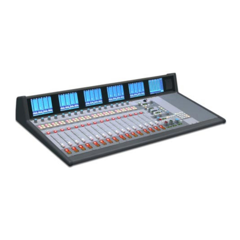
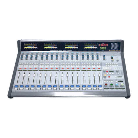
Wheatstone E-5 User manual

E-5 Digital Control Surface
TECHNICAL MANUAL
600 Industrial Drive, New Bern, North Carolina, USA 28562

WHEATSTONE CORPORATION
600 Industrial Drive
New Bern, North Carolina 28562
tel 252-638-7000 / fax 252-637-1285
E-5 Digital Control Surface Technical ManualE-5 Digital Control Surface Technical Manual
E-5 Digital Control Surface Technical Manual
©2008 Wheatstone Corporation
E-5/Apr 2008

AA
AA
ATTENTIONTTENTION
TTENTIONTTENTION
TTENTION
RR
RR
READEAD
EADEAD
EAD MM
MM
M
EE
EE
E!!
!!
!
E-5 / Oct 2008
Attention!
FF
FF
Federal Communications Commission (FCC) Complianceederal Communications Commission (FCC) Compliance
ederal Communications Commission (FCC) Complianceederal Communications Commission (FCC) Compliance
ederal Communications Commission (FCC) Compliance
Notice:Notice:
Notice:Notice:
Notice:
Radio FRadio F
Radio FRadio F
Radio Frequency Noticerequency Notice
requency Noticerequency Notice
requency Notice
NOTE:NOTE:
NOTE:NOTE:
NOTE: This equipment has been tested and found to comply with the
limits for a Class A digital device, pursuant to Part 15 of the FCC rules. These
limits are designed to provide reasonable protection against harmful
interference when the equipment is operated in a commercial environment.
This equipment generates, uses, and can radiate radio frequency energy
and, if not installed and used in accordance with the instruction manual,
may cause harmful interference to radio communications. Operation of this
equipment in a residential area is likely to cause harmful interference in
which case the user will be required to correct the interference at his own
expense.
This is a Class A product. In a domestic environment, thisThis is a Class A product. In a domestic environment, this
This is a Class A product. In a domestic environment, this
product may cause radio interference, in which case, theproduct may cause radio interference, in which case, the
product may cause radio interference, in which case, the
user may be required to take appropriate measures.user may be required to take appropriate measures.
user may be required to take appropriate measures.
This equipment must be installed and wired properly in order to assure
compliance with FCC regulations.
Caution!Caution!
Caution!Caution!
Caution!
Any modifications not expressly approved in writing byAny modifications not expressly approved in writing by
Any modifications not expressly approved in writing by
Wheatstone could void the user's authority to operate this equipment.Wheatstone could void the user's authority to operate this equipment.
Wheatstone could void the user's authority to operate this equipment.

RR
RR
READEAD
EADEAD
EAD MM
MM
M
EE
EE
E!!
!!
!
Apr 2008
IMPORTANT!
Cleaning the Acrylic Surface
An acrylic surface is a beautiful, lustrous material that is outstanding in
durability and break resistance. With proper care, it will retain its attractive
appearanceformanyyearstocome.Thiscareshouldincludeprecautionsagainst
scratchingorcontactwithobjectsofhightemperaturethatmightmarthesurface.
A few simple precautions will preserve the beauty of the acrylic.
• FIRST be sure the surface to be cleaned is powered off.
• NEVER spray or pour any liquid directly onto the surface.
• TO AVOID scratching these surfaces, use a soft brush or cloth to gently
brushawayanylargerdirtparticles.Alternatelythelargerparticlescanbeblown
from the surface with the use of canned air.
• USE a soft, clean lint free cloth or micro fiber cloth and clean lukewarm
water to clean the surface. For stubborn dirt and stains use a mild, nonabrasive
soap and water mixture with the gentle cleaning cloth. Use only light pressure
when cleaning. Avoid rubbing dirt or grit into the surface. Turn the cloth often
andreplacewithacleanclothfrequently.Drybyblottinggentlywithaclean,dry
cloth.
• AVOID using kleenex, paper towels, sponges or other coarse shop towels,
as these materials may contain abrasives that can scratch acrylic surface.
• DO NOT USE ketones, aromatics, esters, halogens, window cleaning
sprays, alcohol, kitchen scouring compounds, or solvents (such as acetone,
benzene, gasoline, carbon tetrachloride, or thinners).
Caution! Donotuseammoniabasedcleaningsolutionsastheycancausethe
surface to yellow, and became brittle and eventually cause structural damage to
the acrylic surface.
Wheatstonewillnotbeliablefordamageresultingfromimpropercleaning
and maintenance.
!

page Contents – 1
E-5 / Apr 2008
CONTENTS
E-5 Technical Manual
Table of Contents
Chapter 1 – General Information
Introduction ...................................................................................1-2
Control Surface Placement ..........................................................1-3
Power Supply ................................................................................1-4
Failsafe Dual Redundant Supply.............................................................................. 1-5
Energizing ................................................................................................................. 1-5
I/O Connections.............................................................................1-6
Getting Started ..............................................................................1-8
Log-In .............................................................................................1-9
Tabbed Navigation ........................................................................1-9
Surface Software Version........................................................... 1-10
Help .............................................................................................. 1-10
Chapter 2 - Input Panel (IPE-5)
Controls and Functions................................................................2-2
SET Button................................................................................................................ 2-2
Input Tab Display...................................................................................................... 2-3
Source Window......................................................................................................... 2-3
Programmable Button Windows ............................................................................... 2-4
Fader Mode Controls and Indicators ........................................................................ 2-5
Pan............................................................................................................................ 2-5
Save.......................................................................................................................... 2-5
Other Physical Switches and LEDs.......................................................................... 2-6
Program Assign ................................................................................................... 2-6
MXM Assign LEDs............................................................................................... 2-6
LED Readout ....................................................................................................... 2-6
CUE Switch.......................................................................................................... 2-6
TB BUS- Switch ................................................................................................... 2-6
Bus-Minus Outputs .............................................................................................. 2-6
Fader.................................................................................................................... 2-7
Channel ON Switch ............................................................................................. 2-7
Channel OFF Switch ........................................................................................... 2-7
Channel Status Buttons Display.......................................................................... 2-7
E-5 / Nov 2009

page Contents – 2
E-5 / Apr 2008
CONTENTS
Chapter 3 - Master Panel (MNE-5)
Controls and Functions................................................................3-2
PAN Control.............................................................................................................. 3-2
MODE Switch............................................................................................................ 3-2
INPUT SOURCE Knob ............................................................................................. 3-3
MXM ASSIGN Switches ........................................................................................... 3-5
MXM Master Controls ............................................................................................... 3-5
MXM Talkback .......................................................................................................... 3-6
CUE Knob ................................................................................................................. 3-6
Monitor Speaker Controls......................................................................................... 3-7
Speaker Muting.................................................................................................... 3-7
Speaker Level Controls ....................................................................................... 3-7
Source Select Switches....................................................................................... 3-7
Programming External Source Switches............................................................. 3-8
Control Room Section ......................................................................................... 3-8
Headphone Section ............................................................................................. 3-8
Headphone Mode ................................................................................................ 3-8
Studio Section...................................................................................................... 3-8
Talkback to Studio ............................................................................................... 3-9
E-5 Monitor Options............................................................................................. 3-9
Events ...................................................................................................................... 3-10
Control Modes - User Permissions.......................................................................... 3-11
Presets Tab Functions............................................................................................. 3-13
Copy a Preset From Channel............................................................................. 3-13
Load a Preset ..................................................................................................... 3-13
Save.................................................................................................................... 3-14
Switched Meters ...................................................................................................... 3-14
Timer Section........................................................................................................... 3-15
Time of Day Clock ................................................................................................... 3-15
Programmable Buttons ............................................................................................ 3-16
VDIP Settings .......................................................................................................... 3-18
Machine Logic.......................................................................................................... 3-20
Optional Glass E Interface....................................................................................... 3-21
Network Settings..................................................................................................... 3-22a
E-5 GUI Main Tab Screen Controls......................................................................... 3-23
E-5 GUI Input Tab Screen Controls ........................................................................ 3-24
E-5 GUI MixMinus Tab Screen Controls ................................................................. 3-25
E-5 GUI Presets Tab Screen Controls .................................................................... 3-26
E-5 GUI Events Tab Screen Controls ..................................................................... 3-27
E-5 GUI Options Tab Screen Controls .................................................................... 3-28
E-5 GUI Input Tab Screens ..................................................................................... 3-29
E-5 GUI Options Tab Screens................................................................................. 3-30
E-5 / Jan 2009

page Contents – 3
E-5 / Apr 2008
CONTENTS
Chapter 4 - Host CPU (HC-3)
Overview ..................................................................................... 4-2
HC-3 BIOS Settings/Format....................................................... 4-2
Ethernet IP Addressing ............................................................. 4-2
Ethernet Interface Wiring .......................................................... 4-2
Mixer Link Wiring ....................................................................... 4-3
Internal Programming Options ................................................. 4-3
Switch Settings .......................................................................... 4-3
SW1 Position 1 - Sample Rate ............................................................................... 4-3
SW1 Position 4 - CAT5 Enable .............................................................................. 4-3
Hook-Ups
“ETH” RJ-45 - Main Ethernet Connector ................................................................ 4-4
“CAT5” RJ-45 - Mixer Link Connector .................................................................... 4-4
“HEADPHONE” - Headphone Connector............................................................... 4-4
Typical Ethernet Cable .............................................................. 4-5
Typical Crossover Cable ........................................................... 4-5
HC-3 Pinouts Drawing ............................................................... 4-6
Chapter 5 - Schematic and Load Sheet Drawings
IPE-5 4 Inputs Panel Switch Card
Schematic ............................................................................................................... 5-2
Load Sheet.............................................................................................................. 5-4
ONSE-5 4 Inputs Panel On/Off Switch Card
Schematic ............................................................................................................... 5-5
Load Sheet.............................................................................................................. 5-6
MNE-5 Master Panel Switch Card
Schematic ............................................................................................................... 5-7
Load Sheet............................................................................................................ 5-10
HC-3 Host Controller Card
Schematic ............................................................................................................. 5-11
Load Sheet............................................................................................................ 5-15
PSU-1 Power Supply
Schematic ............................................................................................................. 5-16
Load Sheet............................................................................................................ 5-17
!
All devices in the
system must be
set to the same
sample rate!
E-5 / Jan 2009

page Contents – 4
E-5 / Apr 2008
CONTENTS
Appendices
Appendix 1
Control Surface Clock ...............................................................A-3
Setting the Time......................................................................................................A-3
Update Options.......................................................................................................A-3
Synchronize ............................................................................................................A-3
Battery Backup .......................................................................................................A-4
Appendix 2
Options Text File ........................................................................A-6
Introduction .............................................................................................................A-6
Modifying The Options Text File.............................................................................A-6
A Simple Example From The File...........................................................................A-7
A Second Example .................................................................................................A-8
An Example File - Complete...................................................................................A-9
Appendix 3
Replacement Parts List ...........................................................A-16

GENERAL INFORMATION
page 1 – 1
E-5 / Apr 2008
General Information
Chapter Contents
Introduction ................................................................................ 1-2
Control Surface Placement ....................................................... 1-3
Power Supply ............................................................................. 1-4
Failsafe Dual Redundant Supply............................................................................ 1-5
Energizing ............................................................................................................... 1-5
I/O Connections.......................................................................... 1-6
Getting Started ........................................................................... 1-8
Log-In .......................................................................................... 1-9
Tabbed Navigation ..................................................................... 1-9
Surface Software Version........................................................ 1-10
Help ........................................................................................... 1-10
E-5 / Nov 2009

GENERAL INFORMATION
page 1 – 2
E-5 / Apr 2008
General Information
Introduction
Designed to integrate flawlessly with the E-series Satellite digital audio network
router, the E-5 control surfaces allow you to easily create large- or small- platform-
based systems that are exceptionally user-friendly and flexible. A simpler version of
our E-6 surface, the E-5 control surface carries less features, keeping the control
surfacesimpletouseyetgivingthe operatorsthefeaturesneededforsomeofthemost
demandingshows.Fourmixoutputbuses,fourmix-minusbuses,andindividualfader
bus minus with talkback are some of the standard features. The E-5 also has event
recall, three monitor outputs, and pan, mode, and phase reverse for each channel. It
supportsmultiplearraysofprogrammableinputchannelandmasterpanelswitchesfor
customized functions like phone, intercom, salvos, or machine commands. The E-5
drives a user-supplied VGA monitor display, via the Embedded E-5 Graphic User
Interface(GUI),providinghi-resREALTIMEgraphicdisplays,productiontools,and
setupscreens(securityprotectedbymultilevelpasscodes).AnRJ-45AudioTransport
MIXER connector on the rear of the control surface serves as the link between the
surface and the network system.

G E N E R A L I NFORMATION
page 1 – 3
E-5 / Apr 2008
Control Surface Placement
The E-5 digital audio control surface is designed for simple drop-in installation
in a counter top. Cutout dimensions (in inches) are shown in the drawings below
for 5 available frame sizes.
Do not connect the E-5 control surface to its power supply (and do not connect
the power supply to the AC power line) until instructed to do so.
33.31
17.83
13.67
1.67
0.955
3.21 2.55
E-5 16 INPUT FRAME
39.57
17.83
E-5 20 INPUT FRAME
45.83
17.83
E-5 24 INPUT FRAME
27.05
17.83
E-5 12 INPUT FRAME
20.79
17.83
E-5 8 INPUT FRAME
18.79 for 8 Fader Input
25.05 for 12 Fader Input
31.31 for 16 Fader Input
37.57 for 20 Fader Input
43.83 for 24 Fader Input
8 INPUT FRAME - 14.17" x 19.19"
CUTOUT DIMENSIONS
12 INPUT FRAME - 14.17" x 25.45"
16 INPUT FRAME - 14.17" x 31.71"
20 INPUT FRAME - 14.17" x 37.97"
24 INPUT FRAME - 14.17" x 44.23"

GENERAL INFORMATION
page 1 – 4
E-5 / Apr 2008
Power Supply
The E-5 control surface is powered by a Wheatstone Model PSU-1
rackmount power supply. This unit occupies two 19” wide rack spaces
(total height 3-1/2”). Convection cooled, it requires ample ventilation
space above and below it.
Note the power supply (supplies)
should be mounted in an equipment
rack within fifteen feet of the control
surface (but no closer than 3 feet).
Avoid locating any high gain equip-
ment (such as phono preamps, tape
recorders,etc.)tooneartherackmount
supplies, to avoid magnetic interfer-
ence into that equipment.
Once the supply is rackmounted,
it should be connected to the control
surface using the factory supplied
cable. The cable has two different
types of connectors on it: a 5-pin fe-
maleconnectorthat connects toeither
one of the control surface’s power
supply connectors, and an 8-pin male
connector that plugs into the power
supply. Redundant, five pin male
“D-SUB”stylepower supply connec-
tors are located at the rear-center area
ofthecontrol surface. Ifyouare using
one supply, connect it to one of the
Power Supply
End
Control Surface
End
Front view of the PSU-1
rackmount power supply
Rear view of the PSU-1
rackmount power supply
Iffailsaferedundantsup-
plieshavebeenordered,
you will be installing two
PSU-1 units.
8
7
6
5
PIN
1
2
3
4
PIN
8-pin Connector
Male
5-pin Connector
Female
Power Supply EndConsole End
4
3
2
1
5
RED, YEL
BLU, BLK
N/C
N/C
N/C
N/C
N/C
N/C
PS Cable Pinou
t
RED
YEL
BLU
BLK
N/C
+V in
-V in

GENERAL INFORMATION
page 1 – 5
E-5 / Apr 2008
control surface connectors (it doesn’t matter which one). If you are
using the failsafe option (two PSU-1 supplies), connect one end of a
power supply cable to either control surface power connector and
connect the other end of the cable to one of the two power supply
connectors. Then use the other cable to connect the second power
supply connector to the remaining control surface power supply
connector.
Note each power supply is fitted with a 3-wire grounded AC cord
that should be plugged into a "clean" AC power source, that is, an AC
sourcethat feedsonlythe controlroom audiogear. Thissourceshould
be a separate feed from those powering lighting, air-conditioning, or
any other non-audio machinery. The third pin ground wire of the AC
source should be tied to the central system ground point.
Failsafe Dual Redundant Supply
Wheatstone failsafe power supply systems use two PSU-1 power
supplies for each piece of powered equipment. Though either is
capableofrunningafullloadonitsown,infailsafeoperationbothunits
runin tandem:if onefails, theother takesover, assuringuninterrupted
operation.
In order for failsafe systems to perform as designed, always have
BOTH rackmount supplies powered up and connected to their associ-
ated equipment.
Energizing
Assuming the E-5 control surface mainframe is properly placed,
and its PSU-1 power supply (or supplies) correctly rackmounted and
connectedtothecontrolsurface,youmaynowenergizetherackmount
power supply by plugging it into the AC mains. The “GOOD” LEDs
onthepowersupplyfrontpanelshouldlightuptoindicatethepresence
of their respective voltages. Individual module switches will assume
factory default settings.
Note: To de-energize the control surface, unplug the rackmount
power supply’s AC cord from the AC mains. Never de-energize the
control surface by disconnecting the cable that connects the control
surface and power supply together.
Once you have verified proper power-up, unplug the rackmount powerOnce you have verified proper power-up, unplug the rackmount power
Once you have verified proper power-up, unplug the rackmount power
supply to de-energize the control surface. You may now proceed to wiresupply to de-energize the control surface. You may now proceed to wire
supply to de-energize the control surface. You may now proceed to wire
up audio and control connections.up audio and control connections.
up audio and control connections.
The power feed recom-
mended in the text is of-
teninstalledandreferred
to in studios as an “iso-
lated AC ground” outlet.
It is usually orange in
color.
!
NOTE: Be sure to align
the connectors properly
by matching the ends
marked by red dots on
the connectors on the
cableandtheequipment!

G E N E R A L I NFORMATION
page 1 – 6
E-5 / Apr 2008
I/O Connections
All user wiring to and from the E-5 control surface is made via connectors
located on the control surface’s rear panel. Two 5-pin male connectors at the
center of the control surface’s rear are for power supply connections. An
external stereo, line level headphone signal plugs into the female DB-9
connector, located next to power supply connectors. This signal is routed to
internal amplifiers that feed the headphone jack, located on the front right-hand
side of the surface’s pan. There are two RJ-45 connectors; the one labeled
ENET connects to a standard Ethernet network switch and the MIXER
connector connects to a specific DSP card in an E-Series SAT cage. A DB-15
VGA monitor connector and two PS-2 connectors for keyboard and mouse
round out the rear panel. The sketch below shows connector locations. For all
wiring pinout connections refer to Chapter 4.
E-5 / Nov 2009
POWER A POWER BKEYBRDVGA
DB-15
MOUSEENET
RJ-45
MIXER
RJ-45 DB-9 PS-2
HEADPHONE
PS-2

GENERAL INFORMATION
page 1 – 7
E-5 / Apr 2008E-5 / Nov 2009
This page is intentionally left blankThis page is intentionally left blank

GENERAL INFORMATION
page 1 – 8
E-5 / Apr 2008
Getting Started
The E-5 control surface comes with the E-5 Embedded Graphical User Interface
(GUI) program, intended to be straightforward in use, controlling and displaying
graphics,production tools,andset upscreens. Allcontrols oftheGUI’s mainscreen are
in fixed positions, except that the FUNCTION DISPLAY area contents change accord-
ing to selected function.
Connect the user-supplied VGA monitor LCD or other display to the DB-15
“MONITOR” connector on the control surface’s rear panel, power up the surface, and
the GUI will appear on the monitor display. A serial or PS-2 mouse may be used for
navigation (mouse port provided on the rear of the surface).
We will also refer throughout this manual to the XPoint program. This program,
which runs on a user-supplied PC running Windows XP, complements the embedded
surface GUI program, providing additional programming and control functionality.
Read more about XPoint in the Wheatstone Evolution Series Digital Audio Network
System Technical Manual.
SOURCE
CHANNELS
BUTTONS
PROGRAM METERS
FUNCTIONS TABS
FUNCTIONS DISPLAY
MONITOR
CONTROLS
ACCESS AUTHORIZATION HELP BUTTON
E-5 / Jan 2009

GENERAL INFORMATION
page 1 – 9
E-5 / Apr 2008
Log-In
When the surface boots, it enters the log in level that was last accessed. Look
inthelower leftcorneroftheVGAscreentoseethebutton thatdisplaythe current
ACCESS AUTHORIZATION level. Pressing this button opens the PASSCODE
ACCESSwindow.Selectauserlevel-Intern,Operator,Production,orEngineer-
ing- with the mouse, then enter a numeric pass code and press the OK button. All
defaultpasscodes are”111”. PleaseseetheMasterPanel -Control Modessection
of this manual for detailed information regarding passcodes.
Tabbed Navigation
The E-5 features a “tabbed” navigation architecture to easily access features
with a minimum number of mouse clicks. There are a few subtleties you need to
befamiliarwithtoefficientlygetaroundthe tabbedsoftwarescreens.This section
introduces you to the tabs; detailed function information is included in the Input
and Master panel sections.
TheE-5VGAmonitorisverticallydividedintotwohalveswithaMETERING
PANEon theleft sideand aFUNCTION PANEon theright side.The MainMenu
Tabbuttonsarelocatedacrossthetopofthefunctiondisplayarea.Youmayaccess
anyoftheMainmenuTabsbysimplyclickingonthem.ToaccessInputfunctions,
pressanInputSETbuttonandtheFunctionPanewilljumptosettingsforthatinput
fader strip.
Notice the “Button Bar” at the bottom of the Input screen. You can access the
powerful DSP and programmable features here.
Main Tab - displays Timer/Clock, Current Event, Switched Meter, and the
External Sources for monitors.
InputTab-displaysinteractiveSource& Programmablebutton windows,Mode,
and Pan settings for the selected channel. Note you must press an Input fader’s
SET button to show the settings for that channel, or click on a CHANNEL
STATUS button in the lower left side of the VGA to access any fader.
InputButtonBar-clickonSource,VDip,Load,andSavetoaccessthesefeatures,
described later.
MixMinus Tab - displays controls for the four Mix-Minus Outputs.
Presets Tab - the E-5 includes the ability to save, copy, and paste the channel’s
settings.SettingsarestoredasPresets.ThePresetPaneallowsyoutomanageand
apply presets to Sources and faders.
E-5 / Jan 2009

GENERAL INFORMATION
page 1 – 10
E-5 / Apr 2008
Events Tab - the E-5 can store a “snapshot” of the entire control surface in a file
calledanEVENT.TheEventPaneisdividedintotwosections.TheEventRecall
section lets you recall previously saved Events. The Event Editor is a manager
for creating, editing, and deleting Events. Optional permissions let you limit
access to Event Recall and Event Editor functions.
OptionsTab-awidevarietyofprogrammableoptionsarefoundheretocustomize
the E-5 for your application.
Note: Each Tab is described in detail in subsequent manual sections.
Surface Software Version
In the event that you need to consult the
factory about the E-5 control surface, you
may need to have the surface software ver-
sion number available. Click the Wheat-
stonelogoonthetopofthestart-upscreento
displaythe“INFORMATION”form,which
shows technical information about the
surface’s software version and connection
status to its companion rack MT link,
Ethernet link, and automation interface.
Help
Pressing the HELP button on the lower right corner of the VGA screen opens
a HELP menu for when Talent needs help with settings such as a mix-minus, or
with surface operation in general.
E-5 / Jan 2009

INPUT PANEL
page 2 – 1
E-5 / Apr 2008
Input Panel (IPE-5)
Chapter Contents
Controls and Functions............................................................. 2-2
SET Button.............................................................................................................. 2-2
Input Tab Display.................................................................................................... 2-3
Source Window....................................................................................................... 2-3
Programmable Button Windows ............................................................................. 2-4
Fader Mode Controls and Indicators ...................................................................... 2-5
Pan.......................................................................................................................... 2-5
Save........................................................................................................................ 2-5
Other Physical Switches and LEDs........................................................................ 2-6
Program Assign ................................................................................................. 2-6
MXM Assign LEDs............................................................................................. 2-6
LED Readout ..................................................................................................... 2-6
CUE Switch........................................................................................................ 2-6
TB BUS- Switch ................................................................................................. 2-6
Bus-Minus Outputs ............................................................................................ 2-6
Fader.................................................................................................................. 2-7
Channel ON Switch ........................................................................................... 2-7
Channel OFF Switch ......................................................................................... 2-7
Channel Status Buttons Display........................................................................ 2-7

INPUT PANEL
page 2 – 2
E-5 / Apr 2008
Input Panel (IPE-5)
Controls and Functions
Each input panel of the E-5 digital audio
controlsurfacehasfouridenticalstripsrepre-
sentingfourinputchannels.Youcontrolhow
each channel is set up by pressing physical
switches on the surface and configuring soft-
ware settings through the Input Tab.
The SET buttonlocatedat thetopof each
fader strip provides access to the Input Tab
locatedontheVGAmonitor.TheInputTabis
thecenter ofcontrol forthe E-5surface. Here
you find easy access to most of the fader
strip’s parameters. The hardware LED indi-
catorsonthefaderstrip lettheoperatorknow
whenaparticularfunctionisactive.Allphysi-
cal switches on a fader strip may be used at
any time without having to press the SET
switch.
SET Button
This switch is at the heart of the opera-
tional control of the surface. SET allows the
operator to access various controls and func-
tions,suchasSourceselection,MXMAssign
configuration, Panning, etc. When you press
theSETbutton,theInputTabdisplaychanges
toshowyou the current settings for thisfader
strip.OnceaSETbuttonhasbeenpressed,the
buttonlightsup,andoperatorinteractionwill
apply to that input channel until a different
inputSETbuttonispressed,oruntilatimeout
ofabout20 seconds has occurred.Timeout is
optional and may be defeated in the Options
Tab.
Certain functions are accessed by using
hardware switches and knobs located on the
MONITOR panel. These shared controls are
accessed by first pressing the SET switch on
the desired fader strip. For example, Mix
Minus bus assignments are switched using
the shared MXM ASSIGN switches.
Table of contents
Other Wheatstone Recording Equipment manuals

Wheatstone
Wheatstone G-6 User manual

Wheatstone
Wheatstone SP-8 User manual

Wheatstone
Wheatstone D-5000 User manual

Wheatstone
Wheatstone ARCUS User manual

Wheatstone
Wheatstone ARCUS User manual

Wheatstone
Wheatstone TV 1000 User manual

Wheatstone
Wheatstone D-8000 User manual

Wheatstone
Wheatstone E-Series Guide

Wheatstone
Wheatstone TV-80 User manual

Wheatstone
Wheatstone M-2 User manual