Echoflex Installation Guide
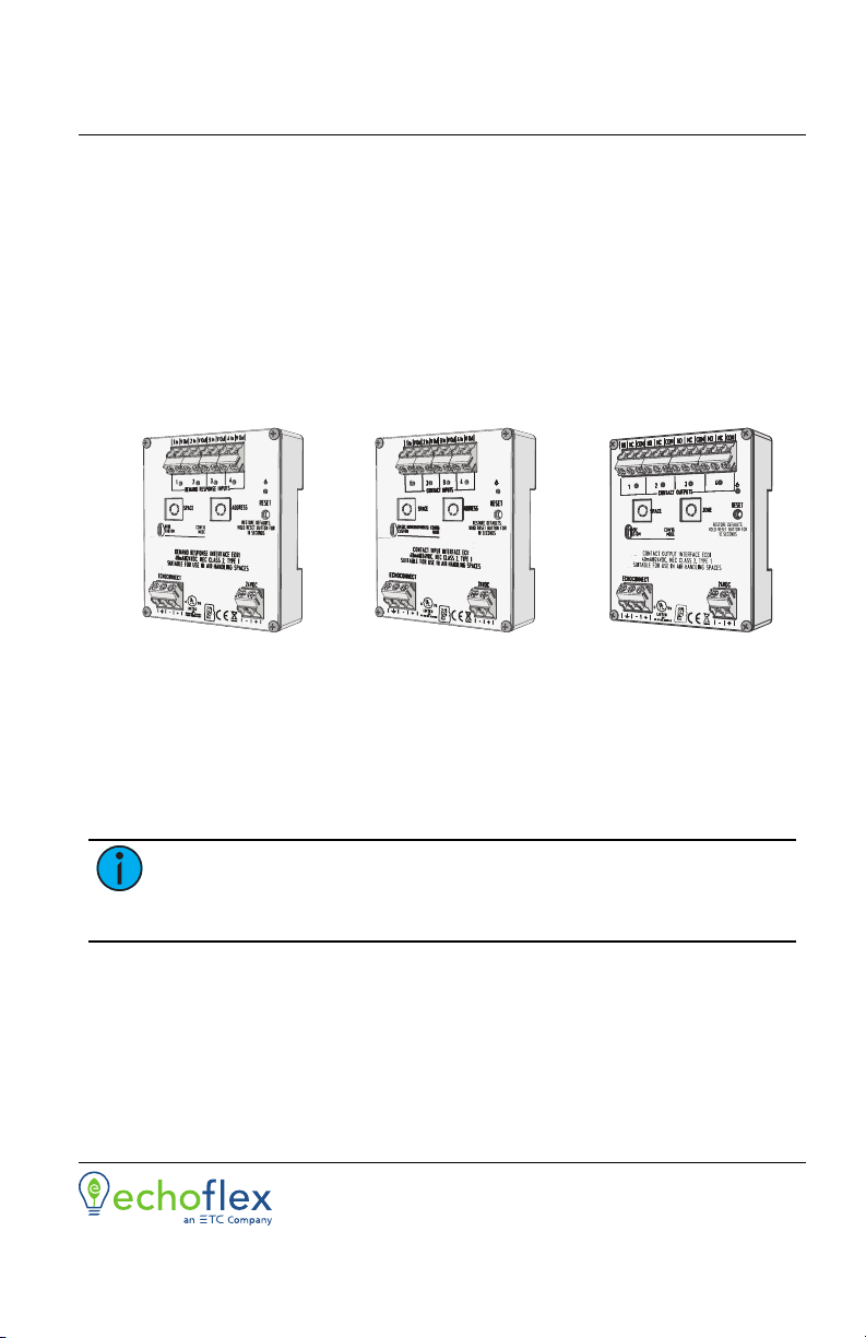
Contact and Demand Response Interfaces
3. Terminate the contact return wire into the negative “-” terminal of
the 24 VDC input. Alternative wiring termination methods may be
required to accommodate multiple terminations.
4. Secure the screws firmly onto each wire for all terminals.
Connect Output Wiring (Output Interface only)
Terminals accept 24-12 AWG (0.2-4 mm2)
1. Strip 3/8” (9-10 mm) of insulation from each wire.
2. Determine the type of output required, normally open (NO) or normally
closed (NC), then loosen the respective output and COM terminals.
3. Insert the common wire into the “COM” terminal and the output wire
into the respective “NO” or “NC” terminal.
4. Secure the screws firmly onto each wire.
Set Configuration Mode
The configuration mode switch allows selection between Basic and Custom
configurations of the interface. Basic is the factory default setting.
Basic
Basic configuration mode applies the following default behaviors:
Input Interface:
Inputs control Presets 1-4 respectively, using momentary input mode where
the closure behaves similar to an Elaho Inspire station.
close / open event (push) executes a preset toggle
holding the contact closed (hold) performs a space raise
closing the closure twice (in rapid succession) performs a preset toggle
with 1/2 second override timing
Note:
Particularly when considering machine driven applications,
Echoflex recommends a minimum of 500ms between any input changes
to ensure transitions are reliably applied.
Demand Response Interface:
Activates Demand Response, affecting up four consecutive Elaho Spaces,
starting with the interface Space rotary switch setting.
Example: Setting the Space switch to 3 results in control of Spaces 3, 4, 5,
and6. A value higher than 13 will result in control of only Spaces 14, 15,
and16.
Note:
Each Elaho space can only have one assigned demand response
input.
Contact and Demand Response Interfaces Page 5 of 8 Echoflex Solutions, Inc.