Safetymarkings:
Read thisfirst:
> Thislightfitting must beinstalledin accordance
withtheBuilding Regulations. Thesemaybe
obtained fromHMSO or viewedand downloaded from
www.communities.gov.uk following the link for Building
Regulations.
> Ifinanydoubt, consultaqualified electrician.
> Switchoffthe mainsbefore commencing installation
and removethe appropriatecircuit fuse.
> Donot usethe fitting withoutthe safety shield fitted.
> Replacethe safety shield ifit is cracked or broken.
> When replacing the lamp,do nottouchwithbare
fingers, grip the lampwithatissue or clean softcloth.
> Donotconnect toacircuitwhichalsohasinductive
loadsconnected asspikesgenerated switching
inductiveloadsmaydamage electroniccomponents
within your PIRdetectorand maycausefalse
triggering.
> Suitable for outdoor use.
> Thisproductissuitable forinstallation onsurfaces with
normal flammability (indicated by the "F" in atriangle )
e.g.wood,plasterboard,masonry.Itisnot suitable for
useon highlyflammable surfaces(e.g.polystyrene,
textiles ).
> Before making fixing hole(s),check thatthere are no
obstructionshidden beneaththe mounting surface
suchas pipes or cables.
> The chosen location of your newfitting should allow for
the product tobesecurelymounted and safely
connected tothe mains supply (lighting circuit ).
> If the location ofyour newfitting requiresthe provision
ofanewelectrical supply, the supplymustconform
withthe requirements ofthe Building Regulations.
> Thisproduct isdesigned for permanentconnection to
fixed wiring:thisshould be either asuitable lighting
circuit (protected witha5or 6AmpMCBor fuse)or a
fused spur (witha3Ampfuse)via afused
connection unit.Werecommend thatthe supply
incorporates aswitchfor easeof operation.
> Makeconnectionstothe electrical supplyin
accordancewiththe following code:
Live-Brownor Red
Neutral -Blue or Black
Earth-Green and Yellow
> This product must be connected toEarth.
> You are advised ateverystage ofyour installation to
double-check anyelectricalconnectionsyou have
made.Afteryouhavecompleted yourinstallation there
are electrical teststhatshould be carried out:these
tests are specified in the Wiring Regulations
(BS7671 )referred toin the Building Regulations. If in
doubt, consult aqualified electrician.
> Choosethe location ofyou newlightfitting giving
consideration tothe following points:
a) There must be atleast 1mbetween the lightfitting
and any illuminated surface.
b) The sensor is designed for optimumperformance
when mounted at aheight of 2.5m.
c)Avoid positioning the unit closetotrees or shrubs
that maycausefalsetriggering during wet or
windy weather.
d) Avoid positioning the unit closetoheat sources
suchas boiler flueswhichmaycausefalse
triggering,
e) Avoid positioning the unit closetobright artificial
light sources whichwill preventthe unit from
operating when the lux control issetfor operation
in dark conditions.
> PIR detectorsare mostsensitivetomovement across
the field of detection—see fig.1b
Installation:
1) Removethebracketfromthe lightbyremoving the
screws and nutsfromeachside. Takecare not tolose
anyoftheseparts asthe nuts are notcaptivewithin
the fitting—see fig.2
2) Fixthe brackettothemounting surfaceusingaspirit
level (ifavailable )toensure thatthe bracketisfixed
level and using appropriatefixings (not supplied ).
3) Attachthe lightfitting tothe bracketusing the screws,
washers and nuts you removed earlier.
4) Rotatethefitting in the bracketsothatthe lightfaces
directlydownwards,thiswill giveyou easy accessto
the connection box fromabove.
5) Removethe cover fromthe connection boxby
removing the four screws and lifting off.
6) Removethe gland nutfromthe side ofthe connection
box and thread your supply cable through.
7) Removetherubber gland fromthe cable entryon the
side of the boxand thread ontothe cable.
8) Thread the supplycable intothe connection boxand
makethe connectionsaccording tothe colour code
listed oppositeand observing the terminal identification
markings inside the connection box.
9) Pushthe rubber gland and nutback along the cable
IP44
until they locatein the threaded cable entry and tighten
the nut sufficiently togrip the cable and makethe entry
water-tight. Donot over-tighten.
10)Replacethe connection box cover and replacethe four
screws. Ensure thatthe sealing gasketiscorrectly
positioned.
11)Adjust the position ofthe lightsothatitilluminatesthe
desired area andlimiting the spread oflightonto
neighbouring property.
12)Tighten thebracketfixingscrewson the sideofthe
fitting tolock inposition.
13)Undo the screwatthetop oftheglass safetyshield on
the frontofthe lightfitting and removethe halogen
lamp.
14)Using asoft,dry,clean cloth,grip the lampand fitit
between the sprung contacts in the lampholder.
15)Closethe glass safety shield and tighten the screw.
Ensure thatthe waterproofing gasketiscorrectly
positioned.
16)Adjust the position ofthe PIRdetector tocover the
desired area.
17)You can check the operation ofthe PIR detector by
performing a“walk test”, see below.
18)Restore the power and switchon.
Timeon adjustment.
(TIMEcontrol )
Turning the timecontrol clockwisereduces the timethat the
lightstays on after activation.Turning itanti-clockwise
increases the timethe lightstayson afteractivation.
Lux level adjustment
(LUX control )
Turning the luxcontrol anti-clockwise(towardsthe sun
symbol )increasesthe ambientlightlevel in whichthe PIR
will operate.Turning itclockwise(towardsthe moon
symbol )will decreasethe ambientlightlevel in whichthe
PIR will operate—see fig.3
Sensitivity(range)
Turn the SENScontrol anti-clockisetoreducethe
sensitivityandhencethe range overwhichthePIRcan
detect movement. Turn clockwisetoincrease.
Walktest
Turn the Luxadjustmentcontrolfullyanti-clockwise
(towardsthesun symbol )and the timecontrolfully
clockwise.The fitting will nowoperatein full daylightand
stay on for between 5and 15 seconds after eachdetection.
Adjust the position of the PIRdetector sothatitistriggered
bymovementin the desired area.Further adjustmentcan
be made byblankingoutsectionsofthe PIR windowwith
opaque tape (not supplied ).
After satisfactorycompletion ofthe walktest,the lux
adjustmentneedstobe settoallowoperation ofthe lightin
darkness. Atatimewhen the ambientlightisatthe level
you want your light toturn on, turn thelux control clockwise
(towardsthe moon symbol )until the lightceasesto
operateand then back slightly.Repeatadjustmentsover
following nights until the operation ofthe light isas desired.
Adjust the timesetting sothatthe lightremainsilluminated
for the desired lengthoftime.
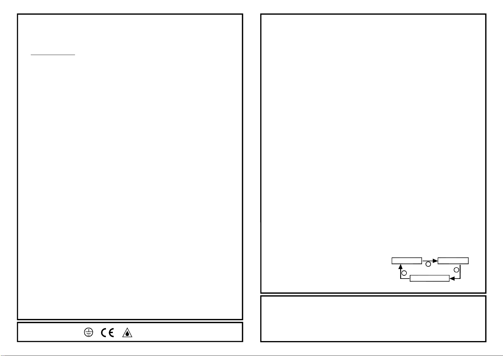
Auto/ Manualmodes
When the power isfirst switched on,the unitentersa
warm-up period forabout1minuteand thendefaultsto
automode.
Oncein automode,turnthe powerofffor approximately4
secondsand then back on again.The light will nowstayon
and be unaffected by the duration or luxcontrol.
If the unitisturned offfor atleast30 seconds, when itis
turned on again itwill enter its warm-up period and then
switchtoautomatic mode.
PIRF500180 Halogen Floodlight 070109PA
Technical information
Operating Voltage:230Vac
Detection angle:180°
Maximum detection range:12m
Timeon:adjustable between 5-15 seconds and 4-5 minutes
Lux level adjustable
POWERON AUTOMODE
MANUALMODE
12
3


