Ethicon Endo-Surgery ECHELON FLEX 45 User manual

Instructions, Instructions, Gebrauchsanweisung, Istruzioni, Instruções,
Instrucciones, Instructies, Brugervejledning, Ohjeet, Οδηγίες, Anvisningar,
Instrukcje, Utasítások, Návod k použití, Návod na použitie, 使用说明
™
®
Please read all information carefully.
Failure to properly follow the instructions may lead to serious surgical consequences, such as leakage or disruption.
Important: This package insert is designed to provide instructions for use of the ECHELON FLEX™45 and ECHELON FLEX™60 Powered
Articulating Endoscopic Linear Cutters. It is not a reference to surgical techniques.
ECHELON FLEX, ENDOPATH and ECHELON are trademarks of Ethicon Endo-Surgery.
agrafeuse linéaire coupante endoscopique articulée électrique,
agrafeuse linéaire coupante endoscopique articulée électrique
compacte et agrafeuse linéaire coupante endoscopique articulée
électrique longue
Powered abwinkelbarer endoskopischer Linear Cutter, Powered
abwinkelbarer endoskopischer Linear Cutter Compact und
Powered langer abwinkelbarer endoskopischer Linear Cutter
Suturatrice endoscopica Linear Cutter articolata a batteria,
Suturatrice endoscopica Linear Cutter articolata compatta a
batteria e Suturatrice endoscopica Linear Cutter lunga articolata
a batteria
Agrafador linear endoscópico articulado eléctrico com corte,
agrafador linear endoscópico articulado eléctrico compacto com
corte e agrafador linear endoscópico articulado eléctrico longo
com corte
Endocortadora lineal articulada eléctrica, endocortadora lineal
articulada compacta eléctrica y endocortadora lineal articulada
larga eléctrica
Powered articuleerbare endoscopische lineaire cutter, powered
compacte articuleerbare endoscopische lineaire cutter en powered
lange articuleerbare endoscopische lineaire cutter
Eldrevet, artikulerende endoskopisk lineært skærende stapler,
eldrevet, kompakt artikulerende endoskopisk lineært skærende
stapler og eldrevet, lang artikulerende endoskopisk lineært
skærende stapler
Sähkökäyttöinen nivelletty endoskooppinen suorasulkuleikkuri,
sähkökäyttöinen pienikokoinen nivelletty endoskooppinen
suorasulkuleikkuri ja sähkökäyttöinen pitkä nivelletty
endoskooppinen suorasulkuleikkuri
Ηλεκτροκίνητος αρθρωτός ενδοσκοπικός ευθύγραμμος
κοπτοράπτης, ηλεκτροκίνητος αρθρωτός ενδοσκοπικός
ευθύγραμμος κοπτοράπτης μικρού μεγέθους και ηλεκτροκίνητος
μακρύς αρθρωτός ενδοσκοπικός ευθύγραμμος κοπτοράπτης
Eldriven Ledad endoskopisk linjärt skärande stapler, eldriven
kompakt ledad endoskopisk linjärt skärande stapler och eldriven
lång ledad endoskopisk linjärt skärande stapler
Automatyczny przegubowy endoskopowy liniowy nóż tnący,
automatyczny kompaktowy przegubowy endoskopowy liniowy
nóż tnący oraz automatyczny długi przegubowy endoskopowy
liniowy nóż tnący
Csuklós endoszkópos lineáris vágógép; kompakt, csuklós
endoszkópos lineáris vágógép; illetve hosszú, csuklós
endoszkópos lineáris vágógép
Napájený kloubový endoskopický lineární nůž, napájený
kompaktní kloubový endoskopický lineární nůž a napájený dlouhý
kloubový endoskopický lineární nůž
Elektrický endoskopický lineárny rezač skĺbom, kompaktný
elektrický endoskopický lineárny rezač skĺbom adlhý elektrický
endoskopický lineárny rezač skĺbom
电动腔镜关节头直线型切割吻合器、电动腔镜关节
头直线型切割吻合器(短型),以及电动腔镜关节头
直线型切割吻合器(长型)
Powered Articulating Endoscopic Linear Cutter, Powered Compact Articulating Endoscopic Linear Cutter, and
Powered Long Articulating Endoscopic Linear Cutter
A88091P00 AMP IFU_1_18_12.indd 1A88091P00 AMP IFU_1_18_12.indd 1 1/18/12 9:29 AM1/18/12 9:29 AM

23
19
18 21
20 15 16
17 12
910 8 6
7
13
32
11
4
5
14 1
1
2
3
4
5
6
A88091P00 AMP IFU_1_18_12.indd 2-3A88091P00 AMP IFU_1_18_12.indd 2-3 1/18/12 9:29 AM1/18/12 9:29 AM

45
9
10
11
7
8a 8b
A88091P00 AMP IFU_1_18_12.indd 4-5A88091P00 AMP IFU_1_18_12.indd 4-5 1/18/12 9:29 AM1/18/12 9:29 AM

67
16
17
15
14
13
12
18
A88091P00 AMP IFU_1_18_12.indd 6-7A88091P00 AMP IFU_1_18_12.indd 6-7 1/18/12 9:29 AM1/18/12 9:29 AM

89
Indications
The ECHELON™ families of endoscopic linear cutters are intended for transection, resection, and/or creation of anastomoses. The instruments
have application in multiple open or minimally invasive general, gynecologic, urologic, thoracic, and pediatric surgical procedures. They can be
used with staple line or tissue buttressing materials. The instruments may also be used for transection and resection of liver parenchyma (hepatic
vasculature and biliary structures), pancreas, kidney and spleen.
Contraindications
• Do not use the instruments on the aorta.
• Do not use the instruments on ischemic or necrotic tissue.
• Do not use any linear cutter on major vessels without making provision for proximal and distal control.
• Tissue thickness should be carefully evaluated before firing any stapler. Refer to ECHELON Reload Product Codes Chart below for
tissue compression requirement (closed staple height) for each staple size. If tissue cannot comfortably compress to the closed staple
height, or easily compresses to less than the closed staple height, the tissue is contraindicated as it may be too thick or too thin for the
selected staple size.
• These instruments are not intended for use when surgical stapling is contraindicated.
Device Description
The ECHELON FLEX Powered Articulating Endoscopic Linear Cutters are sterile, single patient use instruments that simultaneously cut and
staple tissue. There are six staggered rows of staples, three on either side of the cut line. The ECHELON FLEX 45 Powered instruments have a
staple line that is approximately 45 mm long and a cut line that is approximately 42 mm long. The ECHELON FLEX 60 Powered instruments
have a staple line that is approximately 60 mm long and a cut line that is approximately 57 mm long. The shaft can rotate freely in both directions
and an articulation mechanism enables the distal portion of the shaft to pivot to facilitate lateral access to the operative site.
The instruments are packaged with a primary lithium battery pack that must be installed prior to use. There are specific requirements for disposing
of the battery pack. Refer to the Battery Pack Disposal section.
The instruments are packaged without a reload and must be loaded prior to use. A staple retaining cap on the reload protects the staple leg points
during shipping and transportation. The instruments’ lock-out feature is designed to prevent a used or improperly installed reload from being
refired or an instrument from being fired without a reload.
Caution: Do not load the instrument more than 12 times for a maximum of 12 firings per instrument. The use of the instrument with staple line
reinforcement material may reduce the number of firings.
Instrument Product Codes Chart
Instrument Description Shaft
Code Length
PSE45A ECHELON FLEX 45 Powered Articulating Endoscopic Linear Cutter 340 mm
PCE45A ECHELON FLEX 45 Powered Compact Articulating Endoscopic Linear Cutter 280 mm
PLE45A ECHELON FLEX 45 Powered Long Articulating Endoscopic Linear Cutter 440 mm
PSE60A ECHELON FLEX 60 Powered Articulating Endoscopic Linear Cutter 340 mm
PCE60A ECHELON FLEX 60 Powered Compact Articulating Endoscopic Linear Cutter 280 mm
PLE60A ECHELON FLEX 60 Powered Long Articulating Endoscopic Linear Cutter 440 mm
Reload Product Codes Chart
WARNING: The ECHELON FLEX instruments may only be used with the ECHELON reloads.
Reload Closed Staple Reload Number Staple
Code Staple Height Line Length Color of Staples Rows
ECR45M 0.75 mm 45 mm Gray 70 6
ECR45W 1.0 mm 45 mm White 70 6
ECR45B 1.5 mm 45 mm Blue 70 6
ECR45D 1.8 mm 45 mm Gold 70 6
ECR45G 2.0 mm 45 mm Green 70 6
ECR60M 0.75 mm 60 mm Gray 88 6
ECR60W 1.0 mm 60 mm White 88 6
ECR60B 1.5 mm 60 mm Blue 88 6
ECR60D 1.8 mm 60 mm Gold 88 6
ECR60G 2.0 mm 60 mm Green 88 6
MR Conditional
Non-clinical testing has demonstrated the implantable staple made of titanium (Ti3Al2.5V) alloy in the ECHELON 45 and 60 reloads is MR
Conditional. It can be scanned safely under the following conditions:
• Static magnetic field of 3 Tesla.
• Spatial gradient field of 720 Gauss/cm.
• Maximum whole body averaged specific absorption rate (SAR) of 2.7 W/kg for 15 minutes of scanning.
MRI Related Heating
In non-clinical testing, the implantable staple made of titanium (Ti3Al2.5V) alloy in the ECHELON 45 and 60 reloads produced a temperature
rise of less than 2°C at a maximum whole body averaged specific absorption rate (SAR) of 2.7 W/kg, as assessed by calorimetry for 15 minutes
of MR scanning in a (3-Tesla/128-MHz, Excite, Software HDx, Software 14X.M5, General Electric Healthcare, Milwaukee, WI) MR scanner.
Artifact Information
MR image quality may be compromised if the area of interest is in the exact same area or relatively close to the position of the ECHELON 45
and 60 implantable staple. Therefore, optimization of MR imaging parameters to compensate for the presence of this device may be necessary.
The maximum artifact size (i.e., as seen on the gradient echo pulse sequence) per staple extends approximately 3-mm relative to the size and
shape of the implantable staple.
Pulse Sequence T1-SE T1-SE GRE GRE
Signal Void Size (mm2) 17-mm25-mm242-mm224-mm2
Plane Orientation Parallel Perpendicular Parallel Perpendicular
Clinical Section
Examples of procedures in which linear cutters and staplers may be used include:
General Gynecologic Urologic Thoracic
• Anastomoses • Vaginal Hysterectomy • Prostatectomy • Lung Resection and Biopsy
• Partial Gastroplasty • Nephrectomy • Pulmonary Wedge Resection
• Appendectomy • Cystectomy
Illustrations and Nomenclature (Illustration 1)
1. ClosingTrigger
2. Red Firing Trigger Lock
3. Firing Trigger
4. Anvil Release Button
5. Battery Pack
6. Battery Pack Release Tab
7. Manual Override Access Panel
8. Knife Reverse Switch
9. Rotating Knob
10. Articulation Fins
11. Reload (Cartridge)
12. Reload Gripping Surface
13. Reload Alignment Tab
14. Reload Alignment Slot
15. Staple Retaining Cap
16. Anvil Jaw
17. Cartridge Jaw
18. Staple Line
19. Cut Line
20. Proximal Black Line
21. Knife Blade Indicator
Instructions for Use
Prior to Using Instrument
1Verify that the reload size matches the instrument size to be used (e.g. use an ECHELON 60 reload with an ECHELON 60 instrument).
2Become familiar with the articulating action of the instrument by pulling on the fins of the rotating knob with the index finger and
articulating the jaws with the other hand (Illustration 2). As lateral pressure is applied in either direction, the jaws pivot to a maximum
angle of 45 degrees, at which point the pivoting force increases to signal the end of the articulating arc. Maintain the lateral pressure
while releasing the rotating knob to lock the angle of the shaft. After locking the jaws, release the lateral pressure. The jaws will also lock
at approximate 15 and 30 degrees by releasing the rotating knob before the end of the articulation arc. To return the jaws to the straight
position, pull on the fins of the rotating knob to release the lock; the jaws will return automatically.
3Verify compatibility of all instruments and accessories prior to using the instrument (refer to Warnings and Precautions).
A88091P00 AMP IFU_1_18_12.indd 8-9A88091P00 AMP IFU_1_18_12.indd 8-9 1/18/12 9:29 AM1/18/12 9:29 AM

10 11
Preparing the Instrument for Use
4Using sterile technique, remove the instrument, battery pack, and reload from their respective packages. To avoid damage, do not flip the
instrument, battery pack, or reload into the sterile field.
5Install the battery pack. The battery pack must be installed prior to use. Insert the battery pack by lining up the release tabs on the battery
pack with the slots on the rear of the instrument. It can be inserted in either orientation; there is no up or down. (Illustration 3) Ensure
battery pack is fully inserted into the device. An audible click will be heard when the battery pack is fully inserted.
Note: The instrument must be used within 12 hours of inserting the battery pack. Refer to the Battery Pack Disposal section for battery
pack disposal instructions.
6Prior to inserting the reload, ensure the instrument is in the open position (Illustration 1).
7Examine the reload for the presence of a staple retaining cap. If the retaining cap is not in place, discard the reload.
Caution: Tissue thickness should be carefully evaluated prior to using the instrument. Refer to the Reload Product Codes Chart for
proper reload selection.
Caution: Selection of the appropriate staple cartridge should be based upon the combined thicknesses of both the tissue and the staple line
reinforcement material. The use of staple line reinforcement material with the instrument may require an increased force to close and may
reduce the number of times the device may be fired. When using staple line reinforcement material, the instructions of the manufacturer of
the material should be followed.
8Insert the reload by sliding it against the bottom of the cartridge jaw until the cartridge alignment tab stops in the reload alignment slot.
Snap the reload securely in place. Remove the staple retaining cap and discard. (Illustration 4) The instrument is now loaded and ready for
use.
Caution: After removing the staple retaining cap, observe the surface of the new reload. The reload must be replaced with another reload
if any colored drivers are visible. (If colored drivers are visible, the reload may not contain staples.)
Using the Instrument
9Close the jaws of the instrument by squeezing the closing trigger until it locks in place (Illustration 5). An audible click indicates that
the closing trigger and the jaws are locked. When the jaws of the instrument are closed, the red firing trigger lock and firing trigger are
exposed.
Note: Do not pull the red firing trigger lock or firing trigger at this time. The instrument may be partially or completely fired and will need
to be reloaded before using on tissue.
10 Visually inspect the stapler to ensure proper cartridge seating. Introduce the instrument into the body cavity through a trocar of the
appropriate size or through an incision (Illustration 6). When using a trocar, the instrument jaws must be visible past the trocar sleeve
before opening the jaws.
Caution: For insertion and removal of articulating instruments, the jaws of the instrument must be straight, parallel to the shaft of the
instrument. Failure to have the instrument jaws in the straight position will result in difficult insertion or withdrawal of the instrument and
may result in damage to the instrument.
Caution: When placing the instrument through the trocar or incision, avoid inadvertently pulling the red firing trigger lock and the firing
trigger. The instrument may be partially or completely fired and will need to be reloaded before using on tissue. If the instrument is
partially fired, remove the instrument and slide the knife reverse switch forward to return the knife to home position (Illustration 7). To
open the jaws, squeeze the closing trigger, then simultaneously press the anvil release switch on either side of the instrument (Illustration
8a). While pressure is still on the anvil release switch, slowly release the closing trigger (Illustration 8b). Remove the reload and insert a
new one (see Reloading the Instrument). If the instrument is fired completely, the knife will return to home position automatically. Remove
the instrument and insert a new reload (see Reloading the Instrument).
Note: At any time, if the knife reverse switch does not return the knife to home position and the jaws will not open:
a. First, ensure the battery pack is securely installed and the instrument has power (Illustration 9); then, try the knife reverse
switch again (Illustration 7).
b. If the knife still does not return, use the manual override. After the manual override system is used, the instrument is disabled
and cannot be used for any subsequent firings. To use the manual override, remove the access panel labeled “Manual Override” on
the top of the instrument handle. The manual override lever will be exposed. Move the lever forward and backward until it can no
longer be moved. (Illustration 10) The knife will now be in the home position. This can be verified by viewing the position of the
knife blade indicator on the underside of the cartridge jaw (Illustration 11). Discard the instrument.
11 Once in the cavity, squeeze the closing trigger, then simultaneously press the anvil release switch on either side of the instrument
(Illustration 8a). While pressure is still on the anvil release switch, slowly release the closing trigger to reopen the jaws and return the
closing trigger to its original position (Illustration 8b).
12 If needed, rotate the jaws by pushing on the fins of the rotating knob with the index finger using a downward or upward pressure
(Illustration 12). The instrument shaft will rotate freely in either direction.
13 To articulate the jaws inside the body cavity, select an appropriate surface (a body structure, organ, or another instrument) to use as a
grounding surface to bend the jaws, ensuring that it stays within the field of view. Rest the lateral side of the jaws that are opposite to the
desired direction of articulation against the grounding surface (the jaws must be open in order to articulate the instrument). (Illustration 13)
WARNING: Do not attempt to articulate by pressing the front of the jaws against the grounding surface as tissue damage or tissue trauma
may occur (Illustration 14).
Pull the fins of the rotating knob back with the index finger and apply a sweeping motion towards the side articulation is wanted while
gently pushing the instrument handle towards the grounding surface. Maintain the jaws pressed against the grounding surface during this
action. Once the desired articulation angle is reached, release the rotating knob to lock the angle (the instrument will only lock at pre-
determined angles – 15º, 30º and 45º).
Caution: The instrument can only achieve a maximum articulation angle of 45º. When using body structures or organs as a grounding
surface, particular attention should be placed to the visual cues and tactile feedback received from the instrument. When the maximum
angle is reached, the force will increase indicating the maximum angle has been reached. Avoid applying excessive pressure to the tissue
as tissue damage or tissue trauma may occur.
14 Position the instrument around the tissue to be stapled.
Caution: Ensure that the tissue lies flat and is positioned properly between the jaws. Any “bunching” of tissue along the reload,
particularly in the crotch of the jaws, may result in an incomplete staple line.
The distal black lines on the anvil and cartridge channel designate the ends of the staple line. The line on the cartridge channel that reads
“cut” references the cut line on the device. (Illustration 1)
Caution: When positioning the stapler on the application site, ensure that no obstructions such as clips, stents, guide wires, etc. are within
the instrument jaws. Firing over an obstruction may result in incomplete cutting action, improperly formed staples, and/or inability to open
the instrument jaws.
15 After positioning the instrument jaws, close the jaws by squeezing the closing trigger until it locks. (Illustration 5) An audible click
indicates that the closing trigger and the jaws are locked. When the jaws of the instrument are closed, the red firing trigger lock and firing
trigger are exposed.
Caution: Ensure tissue has not extended (extruded) proximal to the proximal black line on the instrument (Illustration 1). Tissue forced
into the instrument proximal to the black line may be transected without staples.
Caution: If the closing trigger is difficult to lock, reposition the instrument and take a smaller amount of tissue. Ensure that the proper
reload selection has been made. (Refer to the Reload Product Codes Chart.)
Caution: If the clamping mechanism becomes inoperative and the jaws do not clamp on tissue, do not fire the instrument. Remove and do
not continue to use instrument.
Caution: The use of staple line buttressing materials with the instrument may require an increased force to close. When using staple line
reinforcement material, the instructions of the manufacturer of the material should be followed.
Note: When firing across thick tissue, holding the jaws in place for 15 seconds after closing and prior to firing may result in better
compression and staple formation.
16 Pull back the red firing-trigger lock to enable the firing trigger to be pulled (Illustration 15).
17 Fire the instrument by pulling the firing trigger; the motor will activate audibly (Illustration 16). Continue to depress the trigger until the
motor stops (audible feedback), in order to reach the end of the transection.
Caution: Since the motor may stop if it stalls, it is important to do a visual check to ensure that the knife blade indicator, on the underside
of the cartridge jaw, has reached the end of the transection.
Caution: Attempting to force the device to complete the firing stroke with too much tissue between the jaws, or with dense/thick tissue
between the jaws, may result in motor stall and the knife will stop. If this happens, release the firing trigger, slide the knife reverse switch
forward, and remove and reload the instrument (Illustration 7). Then, position the instrument around a smaller tissue section or use a more
appropriate reload (refer to the Reload Product Codes Chart).
Note: The motor will slow down when device encounters more force.
18 To complete the firing sequence, release the firing trigger to activate the motor and automatically return the knife to home position where
the motor will stop. In this position, the instrument is locked out until the jaws are opened and re-closed.
Note: If it is necessary to interrupt the firing sequence or it is interrupted inadvertently by releasing the trigger during the firing sequence,
pull the firing trigger again to continue. The status of the transection can be determined by observing the knife blade indicator on the
underside of the cartridge jaw throughout the firing action (Illustration 1). This can be done as often as necessary until the knife reaches its
end where releasing the trigger automatically returns the knife to home position.
Caution: If the instrument locks out, the motor will stop. Release the firing trigger and slide the knife reverse switch forward to return
the knife to the home position (Illustration 7). In this position, the instrument should be removed, opened, and reloaded in order to
continue. To open the jaws, squeeze the closing trigger, then simultaneously press the anvil release switch on either side of the instrument
(Illustration 8a). While pressure is still on the anvil release switch, slowly release the closing trigger (Illustration 8b). Follow the
instructions for Reloading the Instrument.
Note: At any time, if the knife reverse switch does not return the knife to home position and the jaws will not open:
a. First, ensure the battery pack is securely installed and the instrument has power (Illustration 9). Then, try the knife reverse
switch again (Illustration 7).
b. If the knife still does not return, use the manual override.
Caution: After the manual override system is used, the instrument is disabled and cannot be used for any subsequent firings.
To use the manual override, remove the access panel labeled “Manual Override” on the top of the instrument handle. The manual
override lever will be exposed. Move the lever forward and backward until it can no longer be moved. (Illustration 10) The knife
will now be in the home position. This can be verified by viewing the position of the knife blade indicator on the underside of the
cartridge jaw (Illustration 11). Discard the instrument.
Caution: Incomplete firing may result in malformed staples, incomplete cut line, bleeding, and/or difficulty removing the device.
Caution: The use of staple line reinforcement material with the instrument may reduce the number of times the device may be fired. When
using staple line reinforcement material, the instructions of the manufacturer of the material should be followed.
Note: Crossing of staple lines may shorten the life of the instrument.
Caution: If the firing mechanism becomes inoperative, do not continue to use the instrument.
19 To open the jaws, squeeze the closing trigger, then simultaneously press the anvil release switch on either side of the instrument. While
pressure is still on the anvil release switch, slowly release the closing trigger. (Illustration 8).
Caution: If the jaws do not automatically open after the anvil release switch is pressed, first ensure that the knife is in the home position.
The position of the knife can be determined by observing the knife blade indicator under the cartridge jaw. (Illustration 11) If the knife
blade indicator is not in the home position or the position of the knife cannot be determined, slide the knife return switch to activate the
motor and return the knife to home position (Illustration 7). Try opening the jaws again using the anvil release switch. If the jaws do not
open at this point, then gently pull the closing trigger (1) upward (away from the handle) until both firing and closing triggers return to
their original positions.
20 Gently pull the instrument away from the transected tissue and ensure it is released from the jaws.
Caution: Examine the staple lines for pneumostasis/hemostasis and proper staple closure. Minor bleeding can be controlled with manual
sutures or other appropriate techniques.
21 Before removing articulating instruments, move the jaws away from any obstruction inside the body cavity while keeping the jaws open
and within the field of view, and pull on the fins of the rotating knob. The jaws will return to the straight position automatically.
Caution: For insertion and removal of articulating instruments, the jaws of the instrument must be straight, parallel to the shaft of the
instrument. Failure to have the instrument jaws in the straight position will result in diffi
cult insertion or withdrawal of the instrument and
may result in damage to the instrument.
22 To remove the instrument from the cavity, squeeze the closing trigger until it locks, closing the jaws (Illustration 5). Completely withdraw
the instrument in the closed position.
A88091P00 AMP IFU_1_18_12.indd 10-11A88091P00 AMP IFU_1_18_12.indd 10-11 1/18/12 9:29 AM1/18/12 9:29 AM

12 13
Reloading the Instrument
23 Using sterile technique, remove the reload from the package. To avoid damage, do not flip the reload into the sterile field.
24 Prior to reloading, ensure the instrument is in the open position (Illustration 1).
25 Push upward (toward the anvil) to unsnap the reload from the cartridge jaw. Discard the used reload. (Illustration 17)
WARNING: Prior to reloading the instrument, hold the instrument in a vertical position, with anvil and cartridge jaw completely
submerged in sterile solution. Swish vigorously and then wipe the inside and outside surfaces of the anvil and cartridge jaw to clean any
unused staples from the instrument. Do not use the instrument until it has been visually inspected to confirm there are no staples on the
anvil and cartridge jaw.
26 Examine the new reload for the presence of a staple retaining cap. If the retaining cap is not in place, discard the reload.
Caution: Tissue thickness should be carefully evaluated prior to using the instrument. Refer to the Reload Product Codes Chart for
proper reload selection.
Caution: Selection of the appropriate staple cartridge should be based upon the combined thicknesses of both the tissue and the staple line
reinforcement material. The use of staple line reinforcement material with the instrument may require an increased force to close and may
reduce the number of times the device may be fired. When using staple line reinforcement material, the instructions of the manufacturer of
the material should be followed.
27 Insert the new reload by sliding it against the bottom of the cartridge jaw until the cartridge alignment tab stops in the reload alignment
slot. Snap the reload securely in place. Remove the staple retaining cap and discard. The instrument is now reloaded and ready for use.
(Illustration 4)
Caution: After removing the staple retaining cap, observe the surface of the new reload. The reload must be replaced with another reload
if any colored drivers are visible. (If colored drivers are visible, the reload may not contain staples.)
Battery Pack Disposal
The battery pack contains a built-in battery drain and must be installed into the instrument to trigger the automatic battery drain feature. It does
not need to remain in the instrument – it will continue to drain after it has been removed from the instrument. Once removed, depending on your
local regulations, it can be put directly into the battery recycling bin or normal waste stream.
Prior to Installation into the Instrument
If battery pack needs to be disposed of prior to installation into instrument (e.g. product is beyond expiration date indicated on the
package, battery pack is dropped), first install the battery pack into the instrument, then remove, to trigger built-in battery drain.
After Instrument Use
The battery pack must be removed from the instrument prior to disposal.
If battery pack requires decontamination prior to disposal, follow hospital protocol or the Battery Pack Cleaning and Disinfection instructions
below.
To remove the battery pack, squeeze the release tabs and pull the battery pack straight back (Illustration 18).
Note: It is not necessary to disassemble the battery pack.
Battery Pack Cleaning and Disinfection
WARNING: Do not use hospital autoclaves to sterilize or disinfect battery pack.
Manual Cleaning
1Remove the battery pack from the instrument before cleaning.
Note: Battery pack should not be submerged in water or cleaning solutions.
2Clean the battery pack surfaces with a neutral pH detergent or neutral pH enzymatic detergent, prepared according to the manufacturer’s
instructions.
3Use soft bristle brush to manually clean the battery pack with the cleaning solution.
4Ensure areas containing crevices are scrubbed thoroughly.
5Wipe off detergent thoroughly with lukewarm tap water.
6 Perform visual inspection to determine if debris is removed.
7 Repeat cleaning as necessary to obtain a visually clean battery pack.
Chemical Disinfection
Disinfectants should be prepared and used according to the manufacturer’s recommendations. It is recommended that the chemical disinfectant
be wiped off with tap water.
• Simple Green D Pro 3®
• 10% Bleach (sodium hypochlorite solution)
• 70% Isopropyl alcohol
Standard Conventions Used
The Use of Caution,Warning, and Note Statements
Information relative to the completion of a task in a safe and thorough manner will be supplied in the form of a Caution, a Warning, or a Note
statement. These statements are found throughout the documentation.
These statements should be read before continuing to the next step in a procedure.
WARNING: A Warning statement indicates an operating or maintenance procedure, practice, or condition that, if not strictly observed, could
result in personal injury or loss of life.
Caution: A Caution statement indicates an operating or maintenance procedure, practice, or condition that, if not strictly observed, could result in
damage to or destruction of the equipment.
Note: A Note statement indicates an operating or maintenance problem, practice, or condition that is necessary to accomplish a task efficiently.
Warnings and Precautions
• Minimally invasive procedures should be performed only by persons having adequate training and familiarity with minimally invasive
techniques. Consult medical literature relative to techniques, complications, and hazards prior to performance of any minimally invasive
procedure.
• Minimally invasive instruments may vary in diameter from manufacturer to manufacturer. When minimally invasive instruments and
accessories from different manufacturers are employed together in a procedure, verify compatibility prior to initiation of the procedure.
• When using other technologies (e.g., electrocautery) in the procedure, observe the precautions suggested by the original equipment
manufacturer to avoid the hazards associated with their use.
• Failure to properly follow the instructions may lead to serious surgical consequences, such as leakage or disruption.
• Do not load the instrument more than 12 times for a maximum of 12 firings per instrument. The use of the instrument with staple line
reinforcement material may reduce the number of firings.
• The ECHELON FLEX instruments may only be used with the ECHELON reloads.
• Tissue thickness should be carefully evaluated prior to using the instrument. Refer to the Reload Product Codes Chart for proper reload
selection.
• Selection of the appropriate staple cartridge should be based upon the combined thicknesses of both the tissue and the staple line
reinforcement material. The use of staple line reinforcement material with the instrument may require an increased force to close and may
reduce the number of times the device may be fired. When using staple line reinforcement material, the instructions of the manufacturer of
the material should be followed.
• After removing the staple retaining cap, observe the surface of the new reload. The reload must be replaced with another reload if any
colored drivers are visible. (If colored drivers are visible, the reload may not contain staples.)
• For insertion and removal of articulating instruments, the jaws of the instrument must be straight, parallel to the shaft of the instrument.
Failure to have the instrument jaws in the straight position will result in difficult insertion or withdrawal of the instrument and may result
in damage to the instrument.
• When placing the instrument through the trocar or incision, avoid inadvertently pulling the red firing trigger lock and the firing trigger. The
instrument may be partially or completely fired and will need to be reloaded before using on tissue.
• Do not attempt to articulate by pressing the front of the jaws against the grounding surface as tissue damage or tissue trauma may occur.
• The instrument can only achieve a maximum articulation angle of 45º. When using body structures or organs as a grounding surface,
particular attention should be placed to the visual cues and tactile feedback received from the instrument. When the maximum angle is
reached, the force will increase indicating the maximum angle has been reached. Avoid applying excessive pressure to the tissue as tissue
damage or tissue trauma may occur.
• Ensure that the tissue lies flat and is positioned properly between the jaws. Any “bunching” of tissue along the reload, particularly in the
crotch of the jaws, may result in an incomplete staple line.
• When positioning the stapler on the application site, ensure that no obstructions such as clips, stents, guide wires, etc. are within the
instrument jaws. Firing over an obstruction may result in incomplete cutting action, improperly formed staples, and/or inability to open the
instrument jaws.
• Ensure tissue has not extended (extruded) proximal to the proximal black line on the instrument. Tissue forced into the instrument
proximal to the black line may be transected without staples.
• If the closing trigger is difficult to lock, reposition the instrument and take a smaller amount of tissue. Ensure that the proper reload
selection has been made. (Refer to the Reload Product Codes Chart.)
• If the clamping mechanism becomes inoperative and the jaws do not clamp on tissue, do not fire the instrument. Remove and do not
continue to use instrument.
• The use of staple line buttressing materials with the instrument may require an increased force to close. When using staple line
reinforcement material, the instructions of the manufacturer of the material should be followed.
• Attempting to force the trigger to complete the firing stroke with too much tissue between the jaws, or with dense/thick tissue between the
jaws, may result in motor stall and the knife will stop.
A88091P00 AMP IFU_1_18_12.indd 12-13A88091P00 AMP IFU_1_18_12.indd 12-13 1/18/12 9:29 AM1/18/12 9:29 AM

14 15
• Since the motor may stop if it stalls, it is important to do a visual check to ensure that the knife blade indicator, on the underside of the
cartridge jaw, has reached the end of the transection.
• If the instrument locks out, the motor will stop. Release the firing trigger and slide the knife reverse switch forward to return the knife to
the home position. In this position, the instrument should be removed, opened, and reloaded in order to continue.
• After the manual override system is used, the instrument is disabled and cannot be used for any subsequent firings.
• Incomplete firing may result in malformed staples, incomplete cut line, bleeding, and/or difficulty removing the device.
• If the firing mechanism becomes inoperative, do not continue to use the instrument
• If the jaws do not automatically open after the anvil release switch is pressed, first ensure that the knife is in the home position. The
position of the knife can be determined by observing the knife blade indicator under the cartridge jaw. If the knife blade indicator is not
in the home position or the position of the knife cannot be determined, slide the knife return switch to activate the motor and return the
knife to home position. Try opening the jaws again using the anvil release switch. If the jaws do not open at this point, then gently pull the
closing trigger (1) upward (away from the handle) until both firing and closing triggers return to their original positions.
• Examine the staple lines for pneumostasis/hemostasis and proper staple closure. Minor bleeding can be controlled with manual sutures or
other appropriate techniques.
• Prior to reloading the instrument, hold the instrument in a vertical position, with anvil and cartridge jaw completely submerged in sterile
solution. Swish vigorously and then wipe the inside and outside surfaces of the anvil and cartridge jaw to clean any unused staples from
the instrument. Do not use the instrument until it has been visually inspected to confirm there are no staples on the anvil and cartridge jaw.
• Before removing the instrument, be sure tissue is cleared from the jaws and then close the jaws.
• When selecting the cartridge, careful consideration should be given to existing pathologic conditions as well as any pre-surgical treatment,
such as radiotherapy, that the patient may have undergone. Certain conditions or preoperative treatments may cause change in tissue
thickness that would exceed the indicated range of tissue thickness for the standard choice of cartridge.
• When dividing major vascular structures, be sure to adhere to the basic surgical principle of proximal and distal control.
• Do not use hospital autoclaves to sterilize or disinfect battery pack.
• Use of any other type of battery other than the battery supplied with the device may result in increased EMISSIONS or decreased
IMMUNITY of the ECHELON FLEX Powered Articulating Endoscopic Linear Cutter.
• Portable radio and mobile RF communications equipment can effect medical devices. Follow the directions of the following tables when
using the ECHELON FLEX Powered Articulating Endoscopic Linear Cutter.
• Avoid use of the ECHELON FLEX Powered Articulating Endoscopic Linear Cutter adjacent to or stacked with other equipment. If
adjacent or stacked use is necessary, monitor the ECHELON FLEX Powered Articulating Endoscopic Linear Cutter and the other
equipment to assure normal operation.
• Instruments or devices which come into contact with bodily fluids may require special disposal handling to prevent biological
contamination.
• This device is packaged and sterilized for single use only. Do not reuse, reprocess or resterilize. Reuse, reprocessing, or resterilization
may compromise the structural integrity of the device and/or lead to device failure that in turn may result in patient injury, illness or
death. Also, reprocessing or resterilization of single use devices may create a risk of contamination and/or cause patient infection or cross-
infection, including, but not limited to, the transmission of infectious disease(s) from one patient to another. Contamination of the device
may lead to injury, illness, or death of the patient.
Specications
The ECHELON FLEX Powered Articulating Endoscopic Linear Cutter has a power rating of 40 W.
The ECHELON FLEX Powered Articulating Endoscopic Linear Cutter is resistant to water ingress and is classified per IEC 60601-1 as IPXO.
The ECHELON FLEX Powered Articulating Endoscopic Linear Cutter needs special precautions regarding EMC and needs to be installed and
put into service according to the EMC information provided in this document. Portable and mobile RF communications equipment can effect
Medical Electrical Equipment.
WARNING: Use of any other type of battery other than the battery supplied with the device may result in increased EMISSIONS or decreased
IMMUNITY of the ECHELON FLEX Powered Articulating Endoscopic Linear Cutter.
WARNING: Portable radio and mobile RF communications equipment can effect Medical Electrical Equipment. Follow the directions of the
following tables when using the ECHELON FLEX Powered Articulating Endoscopic Linear Cutter.
WARNING: Avoid use of the ECHELON FLEX Powered Articulating Endoscopic Linear Cutter adjacent to or stacked with other equipment. If
adjacent or stacked use is necessary, monitor the ECHELON FLEX Powered Articulating Endoscopic Linear Cutter and the other equipment to
assure normal operation.
Electromagnetic Emissions Guidance
The ECHELON FLEX Powered Articulating Endoscopic Linear Cutter is intended for use in the electromagnetic environment specified
below. The customer or the user of the ECHELON FLEX Powered Articulating Endoscopic Linear Cutter should assure that it is used in such
an environment.
Emissions test Compliance Electromagnetic environment - guidance
Harmonic emissions
IEC 61000-3-2 Not applicable
Voltage fluctuations/
flicker emissions
IEC 61000-3-3
Not applicable
RF emissions
CISPR 14-1
Complies The ECHELON FLEX Powered Articulating Endoscopic Linear Cutter is not
suitable for interconnection with other equipment.
Electromagnetic Immunity Guidance
For electromagnetic immunity, essential performance is: no knife movement without activation of the firing trigger.
The ECHELON FLEX Powered Articulating Endoscopic Linear Cutter is intended for use in the electromagnetic environment specified
below. The customer or the user of the ECHELON FLEX Powered Articulating Endoscopic Linear Cutter should assure that it is used in such
an environment.
Immunity test IEC 60601
Test level
Compliance level Electromagnetic environment –
guidance
Electrostatic
Discharge (ESD)
IEC 61000-4-2
± 6 kV contact
± 8 kV air
± 6 kV contact
± 8 kV air
Floors should be wood, concrete or ceramic tile. If
floors are covered with synthetic material, the relative
humidity should be at least 30 %.
Electrical fast
Transient/burst
IEC 61000-4-4
± 2 kV for power
supply lines
± 1 kV for input/output
lines
Not applicable
Surge
IEC 61000-4-11
± 1 kV line(s) to line(s)
± 2 kV line(s) to earth
Not applicable
Voltage fluctuations/
flicker emissions
IEC 61000-3-3
<5 % UT
(>95 % dip in UT)
for 0,5 cycle
40 % UT
(60 % dip in UT)
for 5 cycles
70 % UT
(30 % dip in UT)
for 25 cycles
<5 % UT
(>95 % dip in UT)
for 5 s
Not applicable
NOTE UT is the a.c. mains voltage prior to application of the test level.
A88091P00 AMP IFU_1_18_12.indd 14-15A88091P00 AMP IFU_1_18_12.indd 14-15 1/18/12 9:29 AM1/18/12 9:29 AM

16 17
Recommended separation distances between portable and mobile RF communications equipment
and the ECHELON FLEX Powered Articulating Endoscopic Linear Cutter
The ECHELON FLEX Powered Articulating Endoscopic Linear Cutter is intended for use in an electromagnetic environment in which
radiated RF disturbances are controlled. The customer or the user of the ECHELON FLEX Powered Articulating Endoscopic Linear Cutter
can help prevent electromagnetic interference by maintaining a minimum distance between portable and mobile RF communications
equipment (transmitters) and the ECHELON FLEX Powered Articulating Endoscopic Linear Cutter as recommended below, according to the
maximum output power of the communications equipment.
Rated maximum output power
of transmitter
W
Separation distance according to frequency of transmitter
m
150 kHz to 80 MHz
Pd 2.1=
80 MHz to 800 MHz
Pd 2.1=
800 MHz to 2,5 GHz
Pd 2.1=
0.01 Not applicable 0.12 0.23
0.1 Not applicable 0.37 0.74
1 Not applicable 1.17 2.33
10 Not applicable 3.69 7.38
100 Not applicable 11.67 23.33
For transmitters rated at a maximum output power not listed above, the recommended separation distance din meters (m) can be estimated
using the equation applicable to the frequency of the transmitter, where P is the maximum output power rating of the transmitter in watts (W)
according to the transmitter manufacturer.
NOTE 1 At 80 MHz and 800 MHz, the separation distance for the higher frequency range applies.
NOTE 2 These guidelines may not apply in all situations. Electromagnetic propagation is affected by absorption and reflection from
structures, objects and people.
The ECHELON FLEX Powered Articulating Endoscopic Linear Cutter is intended for use in the electromagnetic environment specified
below. The customer or the user of the ECHELON FLEX Powered Articulating Endoscopic Linear Cutter should assure that it is used in such
an environment.
Power frequency
(50/60 Hz)
magnetic field
IEC 61000-4-8
3 A/m 3 A/m
Power frequency magnetic fields should be at levels
characteristic of a typical location in a typical
commercial or hospital environment.
NOTE UT is the a.c. mains voltage prior to application of the test level.
The ECHELON FLEX Powered Articulating Endoscopic Linear Cutter is intended for use in the electromagnetic environment specified
below. The customer or the user of the ECHELON FLEX Powered Articulating Endoscopic Linear Cutter should assure that it is used in such
an environment.
Immunity test IEC 60601Test
Level
Compliance
level
Electromagnetic environment –
guidance
Conducted RF
IEC 61000-4-6
Radiated RF
IEC 61000-4-3
3 Vrms
150 kHz to 80 MHz
3 V/m
80 MHz to 2,5 GHz
Not applicable
3 V/m
Portable and mobile RF communications
equipment should be used no closer to any
part of the ECHELON FLEX Powered
Articulating Endoscopic Linear Cutter,
including cables, than the recommended
separation distance calculated from the
equation applicable to the frequency of
the transmitter.
Recommended separation distance
- Not Applicable
80 MHz to 800 MHz
800 MHz to 2.5 GHz
where Pis the maximum output power
rating of the transmitter in watts (W)
according to the transmitter manufacturer
and dis the recommended separation
distance in meters (m).
Field strengths from fixed RF transmitters,
as determined by an electromagnetic site
survey,
a
should be less than the compli-
ance level in each frequency range.
b
Interference may occur in the vicinity of
equipment marked with the following
symbol:
NOTE 1 At 80 MHz and 800 MHz, the higher frequency range applies.
NOTE 2 These guidelines may not apply in all situations. Electromagnetic propagation is affected by absorption and reflection from
structures, objects and people.
a
Field strengths from fixed transmitters, such as base stations for radio (cellular/cordless) telephones and land mobile radios, amateur radio,
AM and FM radio broadcast and TV broadcast cannot be predicted theoretically with accuracy. To assess the electromagnetic environment
due to fixed RF transmitters, an electromagnetic site survey should be considered. If the measured field strength in the location in which the
ECHELON FLEX Powered Articulating Endoscopic Linear Cutter is used exceeds the applicable RF compliance level above, the ECHELON
FLEX Powered Articulating Endoscopic Linear Cutter should be observed to verify normal operation. If abnormal performance is observed,
additional measures may be necessary, such as re-orienting or relocating the ECHELON FLEX Powered Articulating Endoscopic Linear Cutter.
b
Over the frequency range 150 kHz to 80 MHz, field strengths should be less than 3 V/m.
Transport and Storage Conditions
Temperature: -22 ºC – 60 ºC
Relative Humidity: 10% – 80%
Pressure: 500 – 1060 hPa
How Supplied
The ECHELON families of endoscopic linear cutters are supplied sterile for single patient use. Discard after use.
Pd 2.1=
Pd 2.1=
Pd 2.1=
A88091P00 AMP IFU_1_18_12.indd 16-17A88091P00 AMP IFU_1_18_12.indd 16-17 1/18/12 9:29 AM1/18/12 9:29 AM

18 19
agrafeuse linéaire coupante endoscopique articulée électrique, agrafeuse linéaire coupante endoscopique articulée électrique
compacte et agrafeuse linéaire coupante endoscopique articulée électrique longue
Lire attentivement toutes les informations.
Ne pas respecter les instructions peut entraîner des conséquences chirurgicales graves, telles que des fuites ou un agrafage incomplet.
Important : cette notice a pour but de donner des informations sur l’utilisation des agrafeuses linéaires coupantes endoscopiques articulées
électriques ECHELON FLEX™45 et ECHELON FLEX™60. Elle ne constitue pas une référence de techniques chirurgicales.
ECHELON FLEX, ENDOPATH et ECHELON sont des marques commercialess d’Ethicon Endo-Surgery.
Indications
Les gammes d’agrafeuses linéaires coupantes endoscopiques ECHELON™ sont conçues pour la section, la résection et/ou la création d’anastomoses.
Ces instruments sont utilisés lors de multiples interventions en chirurgie à ciel ouvert ou endoscopique : chirurgie générale, gynécologique, urologique,
thoracique et pédiatrique. Ils peuvent être employés avec des matériaux de renforcement de lignes d’agrafes ou de tissus. Ces instruments peuvent
également être utilisés pour la section et la résection du parenchyme hépatique (système vasculaire hépatique et structures biliaires), du pancréas,
des reins et de la rate.
Contre-indications
• Ne pas utiliser ces instruments sur l’aorte.
• Ne pas utiliser ces instruments sur des tissus ischémiques ou nécrosés.
• Ne pas utiliser une agrafeuse linéaire sur les vaisseaux majeurs sans prévoir un contrôle proximal et distal.
• Veiller à évaluer avec soin l’épaisseur du tissu avant de procéder à l’agrafage. Consulter le tableau des codes produit des chargeurs
ECHELON ci-dessous pour connaître les caractéristiques de compression des tissus (hauteur de l’agrafe fermée) pour chaque taille
d’agrafe. Si le tissu ne peut se comprimer aisément pour la hauteur d’agrafe fermée ou qu’il se comprime facilement à une hauteur
inférieure à celle de l’agrafe fermée, le tissu est contre-indiqué car il peut être trop épais ou trop fin pour la taille d’agrafe choisie.
• Ces instruments ne doivent pas être utilisés lorsqu’un agrafage chirurgical est contre-indiqué.
Description du dispositif
Les agrafeuses linéaires coupantes endoscopiques articulées (dites ci-après : agrafeuses linéaires endoscopiques articulées) électriques ECHELON
FLEX sont des instruments stériles à utiliser sur un seul patient lors d’une unique intervention qui permettent une section et un agrafage simultanés des
tissus. Ils possèdent six rangées d’agrafes en quinconce, trois rangées de chaque côté de la ligne de section. Les instruments électriques ECHELON
FLEX 45 possèdent une ligne d’agrafes d’environ 45 mm de long et une ligne de section d’environ 42 mm de long. Les instruments électriques
ECHELON FLEX 60 possèdent une ligne d’agrafes d’environ 60 mm de long et une ligne de section d’environ 57 mm de long. L’axe peut pivoter
librement dans les deux sens et un mécanisme d’articulation permet à la partie distale de l’axe de pivoter pour faciliter l’accès latéral au site opératoire.
Les instruments sont fournis avec une batterie de piles au lithium qui doit être installée avant utilisation. Il convient de respecter les règles
spécifiques à sa mise au rebut (voir section Mise au rebut de la batterie).
Les instruments sont fournis sans chargeur et doivent être chargés avant utilisation. Le chargeur est muni d’un cache qui protège les pointes
des agrafes pendant l’expédition et le transport. Le dispositif de verrouillage est conçu pour empêcher le déclenchement d’un instrument sans
chargeur ou le redéclenchement d’un chargeur épuisé ou mal installé.
Attention : ne pas charger l’instrument plus de 12 fois pour un maximum de 12 déclenchements par instrument. L’utilisation de l’instrument avec
des matériaux de renforcement de lignes d’agrafes peut réduire le nombre d’agrafages.
Tableau de codes produit des instruments
Code de Description Longueur
l’instrument de l’axe
PSE45A ECHELON FLEX 45 Agrafeuse linéaire coupante endoscopique articulée électrique 340 mm
PCE45A ECHELON FLEX 45 Agrafeuse linéaire coupante endoscopique articulée électrique compacte 280 mm
PLE45A ECHELON FLEX 45 Agrafeuse linéaire coupante endoscopique articulée électrique longue 440 mm
PSE60A ECHELON FLEX 60 Agrafeuse linéaire coupante endoscopique articulée électrique 340 mm
PCE60A ECHELON FLEX 60 Agrafeuse linéaire coupante endoscopique articulée électrique compacte 280 mm
PLE60A ECHELON FLEX 60 Agrafeuse linéaire coupante endoscopique articulée électrique longue 440 mm
Tableau des codes produit des chargeurs
MISE EN GARDE : les instruments ECHELON FLEX ne peuvent être utilisés qu’avec les chargeurs ECHELON.
Code Hauteur Longueur de la Couleur Nombre Rangées
du chargeur de l’agrafe fermée ligne d’agrafes du chargeur d’agrafes d’agrafes
ECR45M 0,75 mm 45 mm Gris 70 6
ECR45W 1,0 mm 45 mm Blanc 70 6
ECR45B 1,5 mm 45 mm Bleu 70 6
Code Hauteur Longueur de la Couleur Nombre Rangées
du chargeur de l’agrafe fermée ligne d’agrafes du chargeur d’agrafes d’agrafes
ECR45D 1,8 mm 45 mm Or 70 6
ECR45G 2,0 mm 45 mm Vert 70 6
ECR60M 0,75 mm 60 mm Gris 88 6
ECR60W 1,0 mm 60 mm Blanc 88 6
ECR60B 1,5 mm 60 mm Bleu 88 6
ECR60D 1,8 mm 60 mm Or 88 6
ECR60G 2,0 mm 60 mm Vert 88 6
Compatibilité à l'IRM (Imagerie par Résonance Magnétique) dans certaines conditions
Des expérimentations non cliniques ont démontré que les agrafes implantables fabriquées en alliage de titane (Ti3Al2, 5V) des chargeurs
ECHELON 45 et 60 sont compatibles avec l'IRM sous certaines conditions. Un patient porteur d'agrafes implantées peut subir un scanner en toute
sécurité dans les conditions suivantes :
• Champ magnétique statique de 3 Tesla.
• Champ à gradient spatial de 720 Gauss/cm.
• Taux d'absorption spécifique (TAS) moyen pour le corps entier de 2,7 W/kg maximum pour 15 minutes d'examen par RM.
Échauement lié à l'IRM
Dans les expérimentations non cliniques, les agrafes implantables fabriquées en alliage de titane (Ti3Al2, 5V) des chargeurs ECHELON 45 et 60
ont entraîné une augmentation de la température inférieure à 2 °C, à un taux d'absorption spécifique (TAS) moyen pour le corps entier de 2,7 W/kg
maximum, telle qu'évaluée par calorimétrie pendant 15 minutes d'examen par RM dans un scanner (3 Tesla/128 MHz, Excite, logiciel HDx, 14X.
M5, General Electric Healthcare, Milwaukee, WI).
Informations relatives aux artéfacts
La qualité de l’image RM peut être compromise si la zone d’intérêt se situe exactement dans la même zone ou relativement proche de l'emplacement
des agrafes implantables ECHELON 45 et 60. Par conséquent, l'optimisation des paramètres de l'IRM peut être nécessaire pour compenser la présence
de ce dispositif. La taille maximale d'artéfact (telle qu'observée sur la séquence d'impulsions en écho de gradient) par agrafe s'étend sur environ 3 mm
par rapport à la taille et à la forme de l'agrafe implantable.
Séquence d'impulsions T1-ES T1-ES EGR EGR
Taille de la zone de perte du signal (mm2) 17 mm25 mm242 mm224 mm2
Orientation du plan Parallèle Perpendiculaire Parallèle Perpendiculaire
Section clinique
Les agrafeuse linéaire coupantes peuvent notamment être utilisées dans les procédures suivantes :
Générales Gynécologiques Urologiques Thoraciques
• Anastomoses • Hystérectomie vaginale • Prostatectomie • Résection pulmonaire et biopsie
• Gastroplastie partielle • Néphrectomie • Résection pulmonaire limitée
• Appendicectomie • Cystectomie
Illustrations et nomenclature (illustration 1)
1. Levier de fermeture
2. Verrou rouge du levier de déclenchement de l’agrafage
3. Levier de déclenchement de l’agrafage
4. Bouton de libération de l’enclume
5. Batterie
6. Ergot de libération de la batterie
7. Panneau d’accès d’activation manuelle
8. Commutateur d’inversion du couteau
9. Molette de rotation
10. Pattes d’articulation
11. Chargeur (cartouche)
12. Surface de préhension du chargeur
13. Ergot d’encliquetage du chargeur
14. Encoche d’encliquetage du chargeur
15. Cache de protection des agrafes
16. Mors de l’enclume
17. Mors de la cartouche
18. Ligne d’agrafes
19. Ligne de section
20. Ligne noire proximale
21. Témoin de lame de couteau
A88091P00 AMP IFU_1_18_12.indd 18-19A88091P00 AMP IFU_1_18_12.indd 18-19 1/18/12 9:29 AM1/18/12 9:29 AM

20 21
Notice d’utilisation
Avant d’utiliser l’instrument
1Vérifier que la taille du chargeur correspond à la taille de l’instrument à utiliser (p. ex. utiliser un chargeur ECHELON 60 avec un
instrument ECHELON 60).
2Se familiariser avec le mouvement d’articulation de l’instrument en tirant sur les pattes de la molette de rotation à l’aide de l’index et en
articulant les mors à l’aide de l’autre main (illustration 2). Lorsqu’une pression latérale est exercée dans l’une des directions, les mors
pivotent à un angle maximal de 45 degrés. La résistance à la force giratoire augmente alors pour indiquer la fin de l’arc d’articulation.
Maintenir la pression latérale tout en relâchant la molette de rotation afin de verrouiller l’angle de l’axe. Après avoir verrouillé les mors,
relâcher la pression latérale. Les mors se verrouilleront à environ 15 et 30 degrés en cas de relâchement de la molette de rotation avant la
fin de l’arc d’articulation. Pour ramener les mors en position rectiligne, tirer sur les pattes de la molette de rotation pour libérer le verrou ;
les mors reviendront automatiquement en position.
3Avant d’utiliser le dispositif, vérifier que tous les instruments et accessoires sont compatibles (voir section Avertissements et précautions
d’emploi).
Préparation de l’instrument pour l’utilisation
4Retirer l’instrument, la batterie et le chargeur de leurs emballages respectifs au moyen d’une technique stérile. Ne pas projeter l’instrument,
la batterie ou le chargeur sur le champ stérile pour éviter de les endommager.
5Installer la batterie. Elle doit être installée avant utilisation. Insérer la batterie en alignant ses ergots de libération avec les fentes situées
à l’arrière de l’instrument. Elle peut être insérée dans n’importe quel sens, il n’y a pas de haut ni de bas (illustration 3). Vérifier que la
batterie est entièrement insérée dans l’instrument. Un déclic retentit lorsque la batterie est totalement introduite.
Remarque : l’instrument doit être utilisé dans les 12 heures suivant l’installation de la batterie. Voir la section Mise au rebut de la batterie
pour plus d’instructions sur la mise au rebut de la batterie.
6Avant d’insérer le chargeur, s’assurer que les mors de l’instrument sont ouverts (illustration 1).
7Vérifier que le chargeur est bien équipé de son cache de protection des agrafes. Si le cache de protection n’est pas en place, jeter le chargeur.
Attention : évaluer avec précision l’épaisseur du tissu avant d’utiliser l’instrument. Consulter le tableau des codes produit des
chargeurs pour une sélection correcte du chargeur.
Attention : le choix de la cartouche d’agrafes appropriée doit tenir compte de l’épaisseur combinée des matériaux de renforcement de
lignes d’agrafes et des tissus. L’utilisation de l’instrument avec des matériaux de renforcement de lignes d’agrafes peut exiger une plus
grande force lors de la fermeture et peut réduire le nombre d’activations possibles du dispositif. Lors de l’utilisation de matériaux de
renforcement de lignes d’agrafes, veiller à suivre les instructions du fabricant des matériaux.
8Introduire le chargeur en le faisant glisser à fond le long du mors de la cartouche jusqu’à ce que l’ergot d’encliquetage de la cartouche
s’arrête dans l’encoche d’encliquetage du chargeur. L’encliqueter solidement en place. Retirer le cache de protection des agrafes et le jeter.
(illustration 4) L’instrument est ainsi chargé et prêt à l’emploi.
Attention : après avoir retiré le cache de protection des agrafes, vérifier la surface du nouveau chargeur. Remplacer le chargeur si les
poussoirs colorés sont visibles. (Si les poussoirs colorés sont visibles, il se peut que le chargeur ne contienne pas d’agrafes.)
Utilisation de l’instrument
9Fermer les mors de l’instrument en appuyant sur le levier de fermeture jusqu’à ce qu’il se verrouille (illustration 5). Un déclic indique
que le levier de fermeture et les mors sont verrouillés. Lorsque les mors de l’instrument sont fermés, le verrou rouge du levier de
déclenchement de l’agrafage et le levier de déclenchement de l’agrafage sont exposés.
Remarque : ne pas presser sur le verrou rouge du levier de déclenchement de l’agrafage ni le levier de déclenchement de l’agrafage à ce
stade. L’instrument pourrait être partiellement ou complètement déclenché et devrait être rechargé avant d’être utilisé sur le tissu.
10 Inspecter visuellement l’agrafeuse pour vérifier la bonne installation de la cartouche. Introduire l’instrument dans la cavité corporelle par
un trocart de la taille appropriée ou par une incision (illustration 6). En cas d’utilisation d’un trocart, les mors de l’instrument doivent être
visibles derrière la chemise du trocart, avant l’ouverture des mors.
Attention : pour l’insertion et le retrait des instruments articulés, les mors de l’instrument doivent être rectilignes, parallèles à l’axe. Si les
mors ne sont pas en position rectiligne, l’insertion ou le retrait de l’instrument peut s’avérer difficile et aboutir à sa détérioration.
Attention : lors de l’introduction de l’instrument à travers un trocart ou une incision, éviter de presser accidentellement le verrou
rouge du levier de déclenchement de l’agrafage et le levier de déclenchement de l’agrafage. L’instrument pourrait être partiellement ou
complètement déclenché et devrait être rechargé avant d’être utilisé sur le tissu. Si l’instrument est partiellement déclenché, le retirer
et faire glisser le commutateur d’inversion du couteau vers l’avant afin de ramener le couteau à sa position initiale (illustration 7). Pour
ouvrir les mors, appuyer sur le levier de fermeture, puis appuyer simultanément sur le bouton de libération de l’enclume de part et d’autre
de l’instrument (illustration 8a). Tout en maintenant la pression sur le bouton de libération de l’enclume, relâcher lentement le levier de
fermeture (illustration 8b). Retirer le chargeur et en insérer un nouveau (voir Recharge de l’instrument). Si l’instrument est entièrement
déclenché, le couteau reviendra automatiquement en position initiale. Retirer l’instrument et insérer un nouveau chargeur (voir Recharge
de l’instrument).
Remarque : à tout moment, si le commutateur d’inversion du couteau ne ramène pas le couteau en position initiale et si les mors
ne s’ouvrent pas :
a. D’abord, vérifier que la batterie est solidement installée et que l’instrument est sous tension (illustration 9) ; ensuite, actionner
de nouveau le commutateur d’inversion du couteau (illustration 7).
b. Si le couteau ne revient toujours pas en position, utiliser l’activation manuelle. Une fois l’activation manuelle utilisée,
l’instrument est désactivé et ne peut plus être utilisé pour d’autres agrafages. Pour employer l’activation manuelle, retirer le
panneau d’accès portant la mention “Manual Override” (Activation manuelle) sur le dessus de la poignée de l’instrument. Le
levier d’activation manuelle sera exposé. Déplacer le levier vers l’avant et l’arrière jusqu’à ce qu’il ne puisse plus être déplacé.
(illustration 10) Le couteau est alors en position initiale. Cela peut être vérifié en observant la position du témoin de lame de
couteau sur la partie inférieure du mors de la cartouche (illustration 11). Jeter l’instrument.
11 Une fois dans la cavité, appuyer sur le levier de fermeture, puis appuyer simultanément sur le bouton de libération de l’enclume de part
et d’autre de l’instrument (illustration 8a). Tout en maintenant la pression sur le bouton de libération de l’enclume, relâcher lentement le
levier de fermeture pour rouvrir les mors et ramener le levier à sa position d’origine (illustration 8b).
12 Si besoin, faire pivoter les mors en appuyant vers le haut ou vers le bas sur les pattes de la molette de rotation à l’aide de l’index
(illustration 12). L’axe de l’instrument pivotera librement dans les deux sens.
13 Pour articuler les mors dans la cavité corporelle, sélectionner une surface appropriée (une structure corporelle, un organe ou un autre instrument)
à utiliser comme surface d’assise pour plier les mors, en veillant à ce qu’elle reste dans le champ visuel. Appuyer la partie latérale des mors située
à l’opposé du sens d’articulation désiré contre la surface d’assise (les mors doivent être ouverts pour articuler l’instrument). (illustration 13)
MISE EN GARDE : ne pas tenter d’articuler en appuyant l’avant des mors contre la surface d’assise en raison du risque de survenue de
lésion ou de traumatisme tissulaire (illustration 14).
Tirer les pattes de la molette de rotation vers l’arrière à l’aide de l’index et appliquer un mouvement de balayage dans le sens où l’articulation
est désirée tout en poussant délicatement la poignée de l’instrument vers la surface d’assise. Pendant cette opération, maintenir les mors
appuyés contre la surface d’assise. Une fois l’angle d’articulation désiré atteint, relâcher la molette de rotation pour verrouiller l’angle
(l’instrument ne se verrouillera uniquement qu’à des angles prédéfinis – 15º, 30º et 45º).
Attention : l’instrument peut atteindre un angle d’articulation maximum de 45º seulement. Lorsque les surfaces d’assise sont des
structures corporelles ou des organes, veiller à accorder une attention particulière aux indices visuels et à la rétroaction tactile perçus par
l’intermédiaire de l’instrument. Lorsque l’angle maximal est atteint, la force de résistance augmente indiquant ainsi que l’angle maximal
a été atteint. Éviter d’exercer une pression excessive au niveau des tissus sous peine d’entraîner une lésion ou un traumatisme tissulaire.
14 Positionner l’instrument autour du tissu à agrafer.
Attention : s’assurer que le tissu repose à plat et est correctement positionné entre les mors. Si les tissus forment un « bourrage » le long
du chargeur, en particulier dans la fourche des mors, la ligne d’agrafes risque d’être incomplète.
Les lignes noires, distales sur l’enclume et le canal de chargement désignent les extrémités de la ligne d’agrafes. La ligne du canal de
chargement portant la mention « cut » (coupe) fait référence à la ligne de section du dispositif. (illustration 1)
Attention : lors du positionnement de l’agrafeuse sur le site d’application, vérifier l’absence d’obstacles tels que des clips, des stents,
des guides, etc. qui pourraient se trouver dans les mors de l’instrument. L’agrafage sur un obstacle peut entraîner une section incomplète,
une mauvaise formation des agrafes et/ou l’impossibilité d’ouvrir les mors de l’instrument.
15 Après avoir positionné les mors de l’instrument, les fermer en appuyant sur le levier de fermeture jusqu’à ce qu’il se verrouille.
(illustration 5) Un déclic audible indique que le levier et les mors sont verrouillés. Lorsque les mors de l’instrument sont fermés, le verrou
rouge du levier de déclenchement de l’agrafage et le levier de déclenchement de l’agrafage sont exposés.
Attention : vérifier que le tissu n’a pas dépassé la ligne noire proximale sur l’instrument (illustration 1). Le tissu dans l’instrument
dépassant la ligne noire peut être sectionné sans agrafes.
Attention : Si le levier de fermeture est difficile à verrouiller, repositionner l’instrument et saisir moins de tissus. S’assurer que le
chargeur approprié a été choisi. (Consulter le tableau des codes produit des chargeurs.)
Attention : si le mécanisme de fermeture ne répond plus et si les mors ne serrent pas les tissus, ne pas agrafer. Retirer et arrêter d’utiliser
l’instrument.
Attention : l’utilisation de l’agrafeuse avec des matériaux de renforcement de lignes d’agrafes peut nécessiter une force accrue pour la
fermeture. Lors de l’utilisation de matériaux de renforcement de lignes d’agrafes, veiller à suivre les instructions du fabricant des matériaux.
Remarque : lors de l’agrafage d’un tissu épais, le maintien des mors en place pendant 15 secondes après la fermeture et avant l’agrafage
peut entraîner une meilleure compression et un meilleur agrafage.
16 Tirer le verrou rouge du levier de déclenchement de l’agrafage vers l’arrière pour pouvoir tirer le levier de déclenchement de l’agrafage
(illustration 15).
17 Déclencher l’instrument en pressant le levier de déclenchement de l’agrafage ; le moteur s’active de manière audible (illustration 16).
Continuer d’appuyer sur le levier jusqu’à l’arrêt du moteur (rétroaction sonore) afin d’atteindre la fin de la section.
Attention : étant donné que le moteur peut s’arrêter s’il cale, il est important d’effectuer un contrôle visuel pour s’assurer que le témoin de
lame de couteau, sur la partie inférieure du mors de la cartouche, a atteint la fin de la section.
Attention : tenter de forcer le dispositif à achever un cycle d’agrafage avec trop de tissu ou un tissu dense/épais entre les mors peut faire
caler le moteur et arrêter le couteau. Le cas échéant, relâcher le levier de déclenchement de l’agrafage, glisser le commutateur d’inversion
du couteau vers l’avant, puis retirer et recharger l’instrument (illustration 7). Ensuite, positionner l’instrument autour d’une plus petite
quantité de tissu ou utiliser un chargeur plus approprié (voir le tableau des codes produit des chargeurs).
Remarque : le moteur ralentit lorsque l’instrument rencontre une force de résistance plus importante.
18 Pour terminer la séquence d’agrafage, relâcher le levier de déclenchement de l’agrafage pour activer le moteur et ramener
automatiquement le couteau à sa position initiale, là où le moteur s’arrêtera. Dans cette position, l’instrument est verrouillé jusqu’à ce que
les mors soient ouverts et refermés.
Remarque : s’il est nécessaire d’interrompre la séquence d’agrafage ou si elle est interrompue par inadvertance en relâchant le levier
pendant la séquence, presser de nouveau le levier de déclenchement de l’agrafage pour continuer. L’état de la section peut être déterminé
en observant le témoin de lame de couteau sur le dessous du mors de la cartouche pendant toute l’opération d’agrafage (illustration 1).
Cela peut être fait aussi souvent que nécessaire jusqu’à ce que le couteau arrive à la fin de sa course, là où le relâchement du levier ramène
le couteau automatiquement en position initiale.
Attention : si l’instrument se verrouille, le moteur s’arrête. Relâcher le levier de déclenchement de l’agrafage et faire glisser le commutateur
d’inversion du couteau vers l’avant pour ramener le couteau en position initiale (illustration 7). Dans cette position, l’instrument doit être
retiré, ouvert et rechargé pour continuer. Pour ouvrir les mors, appuyer sur le levier de fermeture, puis appuyer simultanément sur le bouton
de libération de l’enclume de part et d’autre de l’instrument (illustration 8a). Tout en maintenant la pression sur le bouton de libération de
l’enclume, relâcher lentement le levier de fermeture (illustration 8b). Suivre les instructions pour recharger l’instrument.
Remarque : à tout moment, si le commutateur d’inversion du couteau ne ramène pas le couteau en position initiale et si les mors
ne s’ouvrent pas :
a. D’abord, vérifier que la batterie est solidement installée et que l’instrument est sous tension (illustration 9) ; ensuite, actionner
de nouveau le commutateur d’inversion du couteau (illustration 7).
b. Si le couteau ne revient toujours pas en position, utiliser l’activation manuelle.
Attention : une fois l’activation manuelle utilisée, l’instrument est désactivé et ne peut plus être utilisé pour d’autres agrafages.
Pour employer l’activation manuelle, retirer le panneau d’accès portant la mention “Manual Override” (Activation manuelle) sur
le dessus de la poignée de l’instrument. Le levier d’activation manuelle sera exposé. Déplacer le levier vers l’avant et l’arrière
jusqu’à ce qu’il ne puisse plus être déplacé. (illustration 10) Le couteau sera alors en position initiale. Cela peut être vérifié
en observant la position du témoin de lame de couteau sur la partie inférieure du mors de la cartouche (illustration 11). Jeter
l’instrument.
Attention : un déclenchement incomplet peut entraîner une mauvaise formation des agrafes, une ligne de section incomplète, des saignements
et/ou des difficultés pour retirer le dispositif.
Attention : l’utilisation de l’instrument avec des matériaux de renforcement de lignes d’agrafes peut réduire le nombre d’agrafages.
Lors de l’utilisation de matériaux de renforcement de lignes d’agrafes, veiller à suivre les instructions du fabricant des matériaux.
Remarque : un chevauchement des lignes d’agrafes risque de réduire la durée de vie de l’instrument.
Attention : si le mécanisme d’agrafage ne répond plus, ne plus utiliser l’instrument.
19 Pour ouvrir les mors, appuyer sur le levier de fermeture, puis appuyer simultanément sur le bouton de libération de l’enclume de part et
d’autre de l’instrument. Tout en maintenant la pression sur le bouton de libération de l’enclume, relâcher lentement le levier de fermeture.
(illustration 8).
Attention : si les mors ne s’ouvrent pas automatiquement après pression sur le bouton de libération de l’enclume, vérifier d’abord que le
couteau est en position initiale. La position du couteau peut être déterminée en observant le témoin de lame du couteau sous le mors de
A88091P00 AMP IFU_1_18_12.indd 20-21A88091P00 AMP IFU_1_18_12.indd 20-21 1/18/12 9:29 AM1/18/12 9:29 AM

22 23
la cartouche. (illustration 11) Si le témoin ne se trouve pas en position initiale ou s’il est impossible de déterminer la position du couteau,
faire glisser le commutateur d’inversion du couteau pour activer le moteur et ramener le couteau à sa position initiale (illustration 7).
Réessayer d’ouvrir les mors à l’aide du bouton de libération de l’enclume. Si les mors ne s’ouvrent pas, tirer doucement le levier de
fermeture (1) vers le haut (à l’opposé de la poignée) jusqu’à ce que les leviers de déclenchement de l’agrafage et de fermeture retrouvent
leurs positions initiales.
20 Tirer délicatement l’instrument à l’écart du tissu sectionné et vérifier qu’il est dégagé des mors.
Attention : vérifier les lignes d’agrafes pour s’assurer de la fermeture correcte des agrafes et de l’hémostase/aérostase. Un léger
saignement peut être contrôlé au moyen de sutures manuelles ou d’autres techniques appropriées.
21 Avant de retirer les instruments articulés, éloigner les mors de tout obstacle à l’intérieur de la cavité corporelle tout en les gardant ouverts
et dans le champ visuel, et tirer sur les pattes de la molette de rotation. Les mors reviennent automatiquement en position rectiligne.
Attention : pour l’insertion et le retrait des instruments articulés, les mors de l’instrument doivent être rectilignes, parallèles à l’axe. Si les
mors ne sont pas en position rectiligne, l’insertion ou le retrait de l’instrument peut s’avérer difficile et aboutir à sa détérioration.
22 Pour retirer l’instrument de la cavité, fermer les mors en appuyant sur le levier de fermeture jusqu’à ce qu’il se verrouille (illustration 5).
Retirer complètement l’instrument en position fermée.
Recharge de l’instrument
23 Retirer le chargeur de l’emballage en utilisant une technique stérile. Ne pas projeter le chargeur sur le champ stérile pour éviter de
l’endommager.
24 Avant de recharger l’instrument, s’assurer qu’il est en position ouverte (illustration 1).
25 Pousser vers le haut (vers l’enclume) pour dégager le chargeur des mors de la cartouche. Jeter le chargeur usagé. (illustration 17)
MISE EN GARDE : avant de recharger l’instrument, le maintenir à la verticale, avec l’enclume et le mors de la cartouche totalement
immergés dans une solution stérile. Rincer vigoureusement puis essuyer les surfaces intérieures et extérieures de l’enclume et du mors de
la cartouche afin de retirer les agrafes inutilisées de l’instrument. Ne pas utiliser l’instrument tant qu’il n’a pas été inspecté visuellement
pour confirmer l’absence d’agrafes sur l’enclume et le mors de la cartouche.
26 Vérifier que le nouveau chargeur est bien équipé de son cache de protection des agrafes. Si le cache de protection n’est pas en place,
jeter le chargeur.
Attention : évaluer avec précision l’épaisseur du tissu avant d’utiliser l’instrument. Consulter le tableau des codes produit des
chargeurs pour une sélection correcte du chargeur.
Attention : le choix de la cartouche d’agrafes appropriée doit tenir compte de l’épaisseur combinée des matériaux de renforcement de
lignes d’agrafes et des tissus. L’utilisation de l’instrument avec des matériaux de renforcement de lignes d’agrafes peut exiger une plus
grande force lors de la fermeture et peut réduire le nombre d’activations possibles du dispositif. Lors de l’utilisation de matériaux de
renforcement de lignes d’agrafes, veiller à suivre les instructions du fabricant des matériaux.
27 Introduire le nouveau chargeur en le faisant glisser à fond le long du mors de la cartouche jusqu’à ce que l’ergot d’encliquetage de la
cartouche s’arrête dans l’encoche d’encliquetage du chargeur. L’encliqueter solidement en place. Retirer le cache de protection des agrafes
et le jeter. L’instrument est ainsi rechargé et prêt à l’emploi. (illustration 4)
Attention : après avoir retiré le cache de protection des agrafes, vérifier la surface du nouveau chargeur. Remplacer le chargeur si les
poussoirs colorés sont visibles. (Si les poussoirs colorés sont visibles, il se peut que le chargeur ne contienne pas d’agrafes.)
Mise au rebut de la batterie
La batterie intègre un dispositif de décharge et doit être installée dans l’instrument pour déclencher la fonction automatique de décharge de la
batterie. Elle ne doit pas nécessairement rester dans l’instrument, elle continuera à se décharger après en avoir été retirée. Une fois retirée, selon
les réglementations locales, elle peut être placée directement dans un conteneur de recyclage ou jetée avec les déchets normaux.
Avant l’installation dans l’instrument
Si la batterie doit être mise au rebut avant d’avoir été installée dans l’instrument (p. ex. elle a dépassé la date de péremption indiquée sur
l’emballage, elle est tombée), d’abord l’installer dans l’instrument, puis l’en retirer, afin de déclencher la décharge intégrée.
Après l’utilisation de l’instrument
La batterie doit être retirée de l’instrument avant sa mise au rebut.
Si la batterie doit subir une décontamination avant sa mise au rebut, respecter le protocole de l’établissement de santé ou les instructions de la
section Nettoyage et désinfection de la batterie ci-dessous.
Pour retirer la batterie, appuyer sur les ergots de libération et tirer à l’horizontale sur la batterie (illustration 18).
Remarque : il n’est pas nécessaire de démonter la batterie.
Nettoyage et désinfection de la batterie
MISE EN GARDE : ne pas utiliser les autoclaves de l’hôpital pour stériliser ou désinfecter la batterie.
Nettoyage manuel
1Retirer la batterie de l’instrument avant le nettoyage.
Remarque : la batterie ne doit pas être immergée dans l’eau ni dans des solutions détergentes.
2Nettoyer les surfaces de la batterie à l’aide d’un détergent (enzymatique ou non) au pH neutre préparé selon les instructions du fabricant.
3À l’aide d’une brosse à poils souples, nettoyer manuellement la batterie avec la solution détergente.
4Veiller à brosser méticuleusement les zones comportant des rainures.
5Rincer méticuleusement le détergent à l’aide d’eau tiède du robinet.
6 Effectuer une inspection visuelle afin de s’assurer que les débris ont été éliminés.
7 Répéter le nettoyage si besoin pour obtenir une batterie visuellement propre.
Désinfection chimique
Les désinfectants doivent être préparés et utilisés conformément aux recommandations du fabricant. Il est recommandé de rincer le désinfectant
chimique à l’aide d’eau du robinet.
• Simple Green D Pro 3®
• Eau de Javel à 10 % (solution d’hypochlorite de sodium)
• Alcool isopropylique à 70 %
Conventions standard utilisées
Utilisation des mentions Attention, Mise en garde et Remarque
Les informations relatives à la réalisation sûre et précise d’une tâche seront fournies sous la forme des indications suivantes : Attention, Mise en
garde ou Remarque. Ces indications figurent dans l’ensemble de la documentation.
Elles doivent être lues avant de passer à l’étape suivante de la procédure.
MISE EN GARDE : une mise en garde indique une procédure, pratique ou condition de fonctionnement ou d’entretien dont le non-respect strict
risque d’entraîner une lésion ou le décès.
Attention : une mention Attention désigne une procédure, pratique ou condition de fonctionnement ou d’entretien dont le non-respect strict risque
d’entraîner la détérioration ou la destruction de l’équipement.
Remarque : une remarque indique un problème, une pratique ou une condition de fonctionnement ou d’entretien nécessaire pour accomplir une
tâche efficacement.
Avertissements et précautions d’emploi
• Les interventions endoscopiques doivent être réalisées exclusivement par des opérateurs possédant la formation et les connaissances
adéquates en la matière. Consulter la documentation médicale concernant les techniques, complications et risques éventuels avant
d’entreprendre des interventions endoscopiques.
• Le diamètre des instruments endoscopiques peut varier d’un fabricant à l’autre. Pour l’utilisation d’instruments et d’accessoires
endoscopiques de fabricants différents au cours d’une même intervention, vérifier préalablement leur compatibilité.
• Lors de l’utilisation d’autres technologies (p. ex. électrocautérisation) au cours de l’intervention, respecter les précautions suggérées par le
fabricant de l’équipement d’origine afin d’éviter les risques inhérents à leur utilisation.
• Le non-respect des instructions risque d’entraîner des conséquences chirurgicales graves, telles que des fuites ou un agrafage incomplet.
• Ne pas charger l’instrument plus de 12 fois pour un maximum de 12 agrafages par instrument. L’utilisation de l’instrument avec des
matériaux de renforcement de lignes d’agrafes peut réduire le nombre d’agrafages.
• Les instruments ECHELON FLEX ne peuvent être utilisés qu’avec les chargeurs ECHELON.
• Évaluer avec précision l’épaisseur du tissu avant d’utiliser l’instrument. Consulter le tableau des codes produit des chargeurs pour une
sélection correcte du chargeur.
• Le choix de la cartouche d’agrafes appropriée doit tenir compte de l’épaisseur combinée des matériaux de renforcement de lignes
d’agrafes et des tissus. L’utilisation de l’instrument avec des matériaux de renforcement de lignes d’agrafes peut exiger une plus grande
force lors de la fermeture et peut réduire le nombre d’activations possibles du dispositif. Lors de l’utilisation de matériaux de renforcement
de lignes d’agrafes, veiller à suivre les instructions du fabricant des matériaux.
• Après avoir retiré le cache de protection des agrafes, vérifier la surface du nouveau chargeur. Remplacer le chargeur si les poussoirs
colorés sont visibles. (Si les poussoirs colorés sont visibles, il se peut que le chargeur ne contienne pas d’agrafes.)
• Pour l’insertion et le retrait des instruments articulés, les mors de l’instrument doivent être rectilignes, parallèles à l’axe. Si les mors ne
sont pas en position rectiligne, l’insertion ou le retrait de l’instrument peut s’avérer difficile et aboutir à sa détérioration.
• Lors de l’introduction de l’instrument à travers un trocart ou une incision, éviter de presser par inadvertance le verrou rouge du levier
de déclenchement de l’agrafage et le levier de déclenchement de l’agrafage. L’instrument pourrait être partiellement ou complètement
déclenché et devrait être rechargé avant d’être utilisé sur le tissu.
• Ne pas tenter d’articuler en appuyant l’avant des mors contre la surface d’assise en raison du risque de lésion ou de traumatisme tissulaire.
• L’instrument peut atteindre un angle d’articulation maximum de 45º seulement. Lorsque les surfaces d’assise sont des structures
corporelles ou des organes, veiller à accorder une attention particulière aux indices visuels et à la rétroaction tactile perçus par
l’intermédiaire de l’instrument. Lorsque l’angle maximal est atteint, la force de résistance augmente indiquant ainsi que l’angle maximal a
été atteint. Éviter d’exercer une pression excessive au niveau des tissus sous peine d’entraîner une lésion ou un traumatisme tissulaire.
• S’assurer que le tissu repose à plat et est correctement positionné entre les mors. Si les tissus forment un « bourrage » le long du chargeur,
en particulier dans la fourche des mors, la ligne d’agrafes risque d’être incomplète.
• Lors du positionnement de l’agrafeuse sur le site d’application, vérifier l’absence d’obstacles tels que des clips, des stents, des guides, etc.
qui pourraient se trouver dans les mors de l’instrument. L’agrafage sur un obstacle peut entraîner une section incomplète, une mauvaise
formation des agrafes et/ou l’impossibilité d’ouvrir les mors de l’instrument.
• Vérifier que le tissu n’a pas dépassé la ligne noire proximale sur l’instrument. Le tissu dans l’instrument dépassant la ligne noire peut être
sectionné sans agrafes.
• Si le levier de fermeture est difficile à verrouiller, repositionner l’instrument et saisir moins de tissus. S’assurer que le chargeur
approprié a été choisi. (Consulter le tableau des codes produit des chargeurs.)
• Si le mécanisme de fermeture ne répond plus et si les mors ne serrent pas les tissus, ne pas agrafer. Retirer et arrêter d’utiliser l’instrument.
• L’utilisation de l’agrafeuse avec des matériaux de renforcement de lignes d’agrafes peut nécessiter une force accrue pour la fermeture.
Lors de l’utilisation de matériaux de renforcement de lignes d’agrafes, veiller à suivre les instructions du fabricant des matériaux.
• Tenter de forcer le dispositif à achever un cycle d’agrafage avec trop de tissu ou un tissu dense/épais entre les mors peut faire caler le
moteur et arrêter le couteau.
• Étant donné que le moteur peut s’arrêter s’il cale, il est important d’effectuer un contrôle visuel pour s’assurer que le témoin de lame de
couteau, sur la partie inférieure du mors de la cartouche, a atteint la fin de la section.
• Si l’instrument se verrouille, le moteur s’arrête. Relâcher le levier de déclenchement de l’agrafage et faire glisser le commutateur
d’inversion du couteau vers l’avant pour ramener le couteau en position initiale. Dans cette position, l’instrument doit être retiré,
ouvert et rechargé pour continuer.
• Une fois l’activation manuelle utilisée, l’instrument est désactivé et ne peut plus être utilisé pour d’autres agrafages.
A88091P00 AMP IFU_1_18_12.indd 22-23A88091P00 AMP IFU_1_18_12.indd 22-23 1/18/12 9:29 AM1/18/12 9:29 AM

24 25
• Un déclenchement incomplet peut entraîner une mauvaise formation des agrafes, une ligne de section incomplète, des saignements et/ou
des difficultés pour retirer l’instrument.
• Si le mécanisme d’agrafage ne répond plus, ne plus utiliser l’instrument.
• Si les mors ne s’ouvrent pas automatiquement après la pression sur le bouton de libération de l’enclume, vérifier d’abord que le couteau est
en position initiale. La position du couteau peut être déterminée en observant le témoin de lame de couteau sous le mors de la cartouche.
Si le témoin ne se trouve pas en position initiale ou s’il est impossible de déterminer la position du couteau, faire glisser le commutateur
d’inversion du couteau pour activer le moteur et ramener le couteau à sa position initiale. Réessayer d’ouvrir les mors à l’aide du bouton
de libération de l’enclume. Si les mors ne s’ouvrent pas, tirer doucement le levier de fermeture (1) vers le haut (à l’opposé de la poignée)
jusqu’à ce que les leviers de déclenchement de l’agrafage et de fermeture retrouvent leurs positions initiales.
• Vérifier les lignes d’agrafes pour s’assurer de la fermeture correcte des agrafes et de l’hémostase/aérostase. Un léger saignement peut être
contrôlé au moyen de sutures manuelles ou d’autres techniques appropriées.
• Avant de recharger l’instrument, le maintenir à la verticale, avec l’enclume et le mors de la cartouche totalement immergés dans une
solution stérile. Rincer vigoureusement puis essuyer les surfaces intérieures et extérieures de l’enclume et du mors de la cartouche afin
de retirer les agrafes non utilisées de l’instrument. Ne pas utiliser l’instrument tant qu’il n’a pas été inspecté visuellement pour confirmer
l’absence d’agrafes sur l’enclume et le mors de la cartouche.
• Avant de retirer l’instrument, s’assurer qu’il ne reste pas de tissu dans les mors, puis refermer les mors.
• Lors de la sélection de la cartouche, tenir compte attentivement des troubles pathologiques existants et de tout traitement préalable
à l’intervention que le patient a pu subir (p. ex. une radiothérapie). Certains troubles ou traitements préopératoires peuvent entraîner une
modification de l’épaisseur du tissu qui dépasserait alors la gamme indiquée d’épaisseurs de tissus pour le choix standard de la cartouche.
• Lors de la division des structures vasculaires majeures, veiller à se conformer au principe chirurgical fondamental de contrôle proximal
et distal.
• Ne pas utiliser les autoclaves de l’hôpital pour stériliser ou désinfecter la batterie.
• L’utilisation d’une batterie d’un autre type que celle fournie avec le dispositif pourrait entraîner une augmentation des ÉMISSIONS ou une
diminution de l’IMMUNITÉ de l’agrafeuse linéaire endoscopique articulée électrique ECHELON FLEX.
• Les appareils de communication RF portables et mobiles peuvent affecter le fonctionnement des appareils médicaux. Respecter les
consignes des tableaux suivants lors de l’utilisation de l’agrafeuse linéaire endoscopique articulée électrique ECHELON FLEX.
• Éviter d’utiliser l’agrafeuse linéaire endoscopique articulée électrique ECHELON FLEX à proximité ou empilée sur un autre équipement.
Si cette proximité est nécessaire, contrôler l’agrafeuse linéaire endoscopique articulée électrique ECHELON FLEX et l’autre équipement
pour vérifier leur fonctionnement normal.
• Les instruments ou dispositifs qui entrent en contact avec des liquides organiques peuvent nécessiter une méthode de destruction
spécifique pour éviter une contamination biologique.
• Ce dispositif est emballé et stérilisé pour un usage unique seulement. Ne pas réutiliser, reconditionner ou restériliser. La réutilisation,
le retraitement ou la restérilisation risque de compromettre l’intégrité structurelle du dispositif et/ou provoquer sa défaillance et, par conséquent,
entraîner chez le patient une lésion, une maladie ou un décès. De même, le retraitement ou la restérilisation de dispositifs à usage unique peut
entraîner un risque de contamination et/ou provoquer une infection ou une infection croisée chez le patient, notamment, mais non limité à,
la transmission de maladie(s) infectieuse(s) d’un patient à l’autre. La contamination du dispositif peut entraîner chez le patient des lésions,
des maladies ou un décès.
Caractéristiques
L’agrafeuse linéaire endoscopique articulée électrique ECHELON FLEX possède une puissance nominale de 40 W.
L’agrafeuse linéaire endoscopique articulée électrique ECHELON FLEX résiste à la pénétration d’eau et est classifié IPXO selon CEI 60601-1.
L’agrafeuse linéaire endoscopique articulée électrique ECHELON FLEX nécessite des précautions particulières concernant la CEM et doit être
installé et mis en service conformément aux informations de CEM fournies dans ce document. Les équipements de communication RF portables
et mobiles peuvent perturber le fonctionnement de l’équipement électrique médical.
MISE EN GARDE : l’utilisation d’une batterie d’un autre type que celle fournie avec le dispositif pourrait entraîner une augmentation des
ÉMISSIONS ou une diminution de l’IMMUNITÉ de l’agrafeuse linéaire endoscopique articulée électrique ECHELON FLEX.
MISE EN GARDE : les équipements de communication RF portables et mobiles peuvent perturber le fonctionnement de l’équipement électrique
médical. Respecter les consignes des tableaux suivants lors de l’utilisation de l’agrafeuse linéaire endoscopique articulée électrique ECHELON
FLEX.
MISE EN GARDE : éviter d’utiliser l’agrafeuse linéaire endoscopique articulée électrique ECHELON FLEX à proximité ou empilée sur un
autre équipement. Si cette proximité est nécessaire, contrôler l’agrafeuse linéaire endoscopique articulée électrique ECHELON FLEX et l’autre
équipement pour vérifier leur fonctionnement normal.
Consignes concernant les émissions électromagnétiques
L'agrafeuse linéaire endoscopique articulée électrique ECHELON FLEX est destinée à être utilisée dans l'environnement électromagnétique
spécifié ci-dessous. Le client ou l'utilisateur de l'agrafeuse linéaire endoscopique articulée électrique ECHELON FLEX doit s'assurer qu'elle
est utilisée dans ce type d'environnement.
Essai d'émission Conformité Environnement électromagnétique - Consignes
Émissions harmoniques
CEI 61000-3-2 sans objet
Variations de tension/
émissions de papillotement
CEI 61000-3-3
sans objet
Émissions RF
CISPR 14-1
Conforme L'agrafeuse linéaire endoscopique articulée électrique ECHELON FLEX ne
convient pas à une interconnexion avec d'autres équipements.
Consignes concernant l’immunité électromagnétique
Pour l’immunité électromagnétique, les performances essentielles sont : pas de mouvement du couteau sans activation du levier de déclenchement
de l’agrafage.
L'agrafeuse linéaire endoscopique articulée électrique ECHELON FLEX est destinée à être utilisée dans l'environnement électromagnétique
spécifié ci-dessous. Le client ou l'utilisateur de l'agrafeuse linéaire endoscopique articulée électrique ECHELON FLEX doit s'assurer qu'elle
est utilisée dans ce type d'environnement.
Essai d'immunité Niveau de test
CEI 60601
Niveau de conformité Environnement électromagnétique -
Consignes
Décharge
électrostatique (DES)
CEI 61000-4-2
Contact ±6 kV
Air ±8 kV
Contact ±6 kV
Air ±8 kV
Les sols doivent être en bois, en béton ou en carreaux
de céramique. Si les sols sont recouverts d'un matériau
synthétique, l'humidité relative doit être inférieure à
30 %.
Transitoires électriques
rapides en salves
CEI 61000-4-4
± 2 kV pour les lignes
d'alimentation
±1 kV pour les lignes
d'entrée/sortie
sans objet
Surtensions
CEI 61000-4-11
± 1 kV ligne(s) à
ligne(s)
± 2 kV ligne(s) à la
terre
sans objet
Variations de tension/
émissions de
papillotement
CEI 61000-3-3
<5 % UT
(>95 % chute de
tension en UT)
pour 0,5 cycle
40 % UT
(60 % chute de tension
en UT)
pour 5 cycles
70 % UT
(30 % chute de tension
en UT)
pour 25 cycles
<5 % UT
(>95 % chute de
tension pour UT)
pendant 5 s
sans objet
REMARQUE UT correspond à la tension secteur en c.a. avant l'application du niveau de test.
A88091P00 AMP IFU_1_18_12.indd 24-25A88091P00 AMP IFU_1_18_12.indd 24-25 1/18/12 9:29 AM1/18/12 9:29 AM

26 27
L'agrafeuse linéaire endoscopique articulée électrique ECHELON FLEX est destinée à être utilisée dans l'environnement électromagnétique
spécifié ci-dessous. Le client ou l'utilisateur de l'agrafeuse linéaire endoscopique articulée électrique ECHELON FLEX doit s'assurer qu'elle
est utilisée dans ce type d'environnement.
Champ magnétique à la
fréquence du réseau
(50/60 Hz)
CEI 61000-4-8
3 A/m 3 A/m
Les champs magnétiques à la fréquence du réseau
doivent être aux niveaux particuliers d'un environnement
type commercial ou hospitalier.
REMARQUE UT correspond à la tension secteur en c.a. avant l'application du niveau de test.
L'agrafeuse linéaire endoscopique articulée électrique ECHELON FLEX est destinée à être utilisée dans l'environnement électromagnétique
spécifié ci-dessous. Le client ou l'utilisateur de l'agrafeuse linéaire endoscopique articulée électrique ECHELON FLEX doit s'assurer qu'elle
est utilisée dans ce type d'environnement.
Essai d'immunité Niveau de test
CEI 60601
Niveau de
conformité
Environnement électromagnétique -
Consignes
Fréquences
radioélectriques par
conduction
CEI 61000-4-6
Fréquences
radioélectriques par
rayonnement
CEI 61000-4-3
3 V efficaces
150 kHz à 80 MHz
3 V/m
80 MHz à 2,5 GHz
sans objet
3 V/m
L'équipement de télécommunications RF
portable et mobile doit être utilisé loin de
l'agrafeuse linéaire endoscopique articulée
électrique ECHELON FLEX (câbles
compris) à une distance correspondant
à la distance de séparation recommandée,
calculée par l'équation applicable à la
fréquence du transmetteur.
Distance de séparation recommandée
Pd =1,2 - sans objet
Pd =1,2 80 MHz à 800 MHz
Pd =1,2 800 MHz à 2,5 GHz
où Pest la puissance nominale de sortie
maximale du transmetteur en watts (W)
selon le fabricant du transmetteur, et dla
distance de séparation recommandée en
mètres (m).
La puissance des champs des transmetteurs
RF fixes, déterminée par des mesures
électromagnétiques sur site
a
doit être
inférieure au niveau de conformité dans
chaque plage de fréquence.
b
Une interférence peut se produire
à proximité des équipements portant
le symbole suivant :
REMARQUE 1 À 80 MHz et 800 MHz, la plage de fréquence la plus élevée s'applique.
REMARQUE 2 Ces consignes peuvent ne pas s'appliquer dans toutes les situations. La propagation électromagnétique est affectée par
l'absorption et la réflexion des structures, objets et personnes.
a
La puissance de champ des transmetteurs fixes tels que les stations de base pour radiotéléphones (cellulaires/sans fil), radios terrestres
mobiles, radio-amateurs, pour diffusion des émissions de radiodiffusion des bandes AM et FM et des émissions de télévision, ne peuvent pas
être prédites théoriquement avec précision. Pour évaluer l'environnement électromagnétique dû à des transmetteurs RF fixes, une évaluation
électromagnétique sur site doit être envisagée. Si la puissance du champ mesurée à l'endroit dans lequel l'agrafeuse linéaire endoscopique
articulée électrique ECHELON FLEX est utilisée dépasse le niveau de conformité RF ci-dessus applicable, l'agrafeuse linéaire endoscopique
articulée électrique ECHELON FLEX doit être surveillée pour vérifier son bon fonctionnement. En cas de dysfonctionnement, des mesures
supplémentaires peuvent être nécessaires, comme la réorientation ou le déplacement de l'agrafeuse linéaire endoscopique articulée électrique
ECHELON FLEX.
b
Sur la plage de fréquence de 150 kHz à 80 MHz, les puissances des champs doivent être inférieures à 3 V/m.
Distances de séparation recommandées entre l'équipement de télécommunications RF portable et mobile
et l'agrafeuse linéaire endoscopique articulée ECHELON FLEX
L'agrafeuse linéaire endoscopique articulée électrique ECHELON FLEX est destinée à être utilisée dans un environnement électromagnétique
dans lequel les perturbations RF rayonnées sont contrôlées. L'acheteur ou l'utilisateur de l'agrafeuse linéaire endoscopique articulée électrique
ECHELON FLEX peut contribuer à éviter une interférence électromagnétique en maintenant une distance minimale entre l'équipement de
télécommunications RF portable et mobile (transmetteur) et l'agrafeuse linéaire endoscopique articulée électrique ECHELON FLEX, comme
recommandé ci-dessous, selon la puissance de sortie maximale de l'équipement de télécommunications.
Puissance de sortie maximale
du transmetteur
(W)
Distance de séparation selon la fréquence du transmetteur
(m)
150 kHz à 80 MHz
Pd =1,2
80 MHz à 800 MHz
Pd =1,2
800 MHz à 2,5 GHz
Pd =1,2
0,01 sans objet 0,12 0,23
0,1 sans objet 0,37 0,74
1 sans objet 1,17 2,33
10 sans objet 3,69 7,38
100 sans objet 11,67 23,33
Pour les transmetteurs évalués à une puissance de sortie maximale non énumérée ci-dessus, la distance de séparation den mètres (m) recommandée
peut être estimée au moyen de l'équation applicable à la fréquence du transmetteur, où P est la puissance de sortie maximale du transmetteur en
watts (W) selon le fabricant du transmetteur.
REMARQUE 1 À 80 MHz et 800 MHz, la distance de séparation pour la plage de fréquence la plus élevée s'applique.
REMARQUE 2 Ces consignes peuvent ne pas s'appliquer dans toutes les situations. La propagation électromagnétique est affectée par
l'absorption et la réflexion des structures, objets et personnes.
Conditions de transport et de stockage
Température : -22 ºC – 60 ºC
Humidité relative : 10 % – 80 %
Pression : 500 – 1 060 hPa
Présentation
Les agrafeuses linéaires endoscopiques de la gamme ECHELON sont fournies stériles et sont à utiliser sur un seul patient lors d’une unique
intervention. Jeter après utilisation.
A88091P00 AMP IFU_1_18_12.indd 26-27A88091P00 AMP IFU_1_18_12.indd 26-27 1/18/12 9:29 AM1/18/12 9:29 AM

28 29
Powered abwinkelbarer endoskopischer Linear Cutter, Powered abwinkelbarer endoskopischer Linear Cutter Compact und
Powered langer abwinkelbarer endoskopischer Linear Cutter
Bitte alle Angaben sorgfältig lesen.
Nicht ordnungsgemäße Anwendung kann zu ernsthaften chirurgischen Komplikationen, wie z. B. Leckagen oder einer unvollständigen
Klammernahtreihe, führen.
Wichtig: Die Packungsbeilage gibt lediglich Informationen für die Anwendung der ECHELON FLEX™45 und ECHELON FLEX™60 Powered
abwinkelbaren endoskopischen Linear Cutter. Sie stellt keine Empfehlung für chirurgische Techniken dar.
ECHELON FLEX, ENDOPATH und ECHELON sind Warenzeichen von Ethicon Endo-Surgery.
Indikationen
Die ECHELON™-Familie der endoskopischen Linear Cutter ist bei einer Vielzahl von offen und minimal-invasiven Verfahren in der
Allgemeinchirurgie, Gynäkologie, Urologie, Thoraxchirurgie und Pädiatrie zum Durchtrennen, Resezieren und/oder Erstellen von Anastomosen
vorgesehen und können zusammen mit Nahtwiderlagern eingesetzt werden. Die Instrumente können auch zum Durchtrennen und Resezieren
von Leberparenchym (hepatische Gefäßversorgung und biliäre Strukturen), Pankreas, Niere und Milz eingesetzt werden.
Gegenanzeigen
• Die Instrumente nicht an der Aorta einsetzen.
• Die Instrumente nicht bei ischämischen oder nekrotischen Geweben einsetzen.
• Linear Cutter dürfen an Hauptgefäßen nicht ohne vorherige proximale und distale Kontrolle ausgelöst werden.
• Vor Auslösen des Instruments sollte die Gewebedicke sorgfältig überprüft werden. Die geschlossene Klammerhöhe für die einzelnen
Klammergrößen sind der Tabelle mit den Bestell-Nummern der ECHELON Magazine zu entnehmen. Lässt sich das Gewebe nicht
problemlos auf die geschlossene Klammerhöhe komprimieren oder sich leicht darunter komprimieren, ist der Einsatz des Instruments
an diesem Gewebe kontraindiziert, da es möglicherweise für die ausgewählte Klammergröße zu dick oder zu dünn ist.
• Die Instrumente dürfen nicht eingesetzt werden, wenn chirurgisches Klammern kontraindiziert ist.
Produktbeschreibung
Die ECHELON FLEX Powered abwinkelbaren endoskopischen Linear Cutter sind sterile Einweg-Instrumente, die nur für den Einsatz bei einem
Patienten vorgesehen sind. Die geladenen ECHELON 45 Instrumente erstellen zwei dreireihige Klammernähte von ungefähr 45 mm Länge mit
gegeneinander versetzten Klammern. Gleichzeitig durchtrennen sie das Gewebe über eine Länge von etwa 42 mm. Die geladenen ECHELON
FLEX 60 Instrumente erstellen zwei dreireihige Klammernähte von ungefähr 60 mm mit gegeneinander versetzten Klammern. Gleichzeitig
durchtrennen sie das Gewebe zwischen den Klammernahtreihen über eine Länge von etwa 57 mm. Der Schaft kann in beide Richtungen gedreht
werden. Er verfügt über einen Gelenkmechanismus, mit dem der distale Teil des Schafts abgewinkelt werden kann, um den lateralen Zugang zum
Operationssitus zu erleichtern.
Die Instrumente werden mit einer primären Lithium-Batterie geliefert, die vor Verwendung des Instruments eingesetzt werden muss. Für die
Entsorgung der Batterie gelten bestimmte Anforderungen. Siehe Abschnitt „Entsorgung der Batterie“.
Die Instrumente werden ohne Magazin geliefert und müssen vor dem Einsatz geladen werden. Der Klammerschutz am Magazin sorgt für genaue
Klammerausrichtung und schützt die Klammerbeine während des Versands und Transports. Die Instrumente sind mit einer Sicherheitsautomatik
ausgestattet, die das Auslösen eines bereits benutzten oder falsch eingelegten Magazins oder eines ungeladenen Instruments verhindert.
Achtung: Die Instrumente können während eines Eingriffs bis zu zwölfmal geladen und somit zwölfmal bei einem Patienten eingesetzt werden.
Bei Einsatz in Verbindung mit Nahtwiderlagern sind die Instrumente eventuell nicht so oft nachladbar.
Bestell-Nummern der Instrumente
Best.-Nr. des Beschreibung Schaft-
Instruments länge
PSE45A ECHELON FLEX 45 Powered abwinkelbarer endoskopischer Linear Cutter 340 mm
PCE45A ECHELON FLEX 45 Powered abwinkelbarer endoskopischer Linear Cutter Compact 280 mm
PLE45A ECHELON FLEX 45 Powered langer abwinkelbarer endoskopischer Linear Cutter 440 mm
PSE60A ECHELON FLEX 60 Powered abwinkelbarer endoskopischer Linear Cutter 340 mm
PCE60A ECHELON FLEX 60 Powered abwinkelbarer endoskopischer Linear Cutter Compact 280 mm
PLE60A ECHELON FLEX 60 Powered langer abwinkelbarer endoskopischer Linear Cutter 440 mm
Bestell-Nummern der Magazine
WARNUNG: Die ECHELON FLEX Instrumente dürfen nur zusammen mit ECHELON Magazinen eingesetzt werden.
Best.-Nr. des Geschlossene Länge der Farbe des Anzahl der Klammer-
Magazins Klammerhöhe Klammernaht Magazins Klammern nahtreihen
ECR45M 0,75 mm 45 mm Grau 70 6
ECR45W 1,0 mm 45 mm Weiß 70 6
ECR45B 1,5 mm 45 mm Blau 70 6
ECR45D 1,8 mm 45 mm Goldfarben 70 6
Best.-Nr. des Geschlossene Länge der Farbe des Anzahl der Klammer-
Magazins Klammerhöhe Klammernaht Magazins Klammern nahtreihen
ECR45G 2,0 mm 45 mm Grün 70 6
ECR60M 0,75 mm 60 mm Grau 88 6
ECR60W 1,0 mm 60 mm Weiß 88 6
ECR60B 1,5 mm 60 mm Blau 88 6
ECR60D 1,8 mm 60 mm Goldfarben 88 6
ECR60G 2,0 mm 60 mm Grün 88 6
Bedingt MR-sicher
Nichtklinische Tests haben gezeigt, dass die implantierbare Klammer aus Titanlegierung (Ti3AI2.5V) in den ECHELON 45 und 60 Magazinen
bedingt MR-sicher ist. Sie kann unter den folgenden Bedingungen sicher gescannt werden:
• Statisches Magnetfeld: 3 Tesla.
• Räumlicher Magnetfeldgradient: 720 Gauss/cm.
• Maximale durchschnittliche spezifische Absorptionsrate (SAR) für den gesamten Körper: 2,7 W/kg bei 15 Minuten Untersuchung.
MR-bedingte Erwärmung
In nichtklinischen Tests kam es bei der implantierbaren Klammer aus Titanlegierung (Ti3Al2.5V) in den ECHELON 45 und 60 Magazinen bei 15
Minuten Kernspintomographie in einem MR-Scanner (3-Tesla/128-MHz, Excite, Software HDx, Software 14X.M5, General Electric Healthcare,
Milwaukee, WI) zu einem durch Kalorimetrie beurteilten Temperaturanstieg von weniger als 2 °C bei einer maximalen durchschnittlichen
spezifischen Absorptionsrate (SAR) für den gesamten Körper von 2,7 W/kg.
Artefaktinformationen
Die Qualität der MR-Aufnahme kann beeinträchtigt sein, falls die untersuchte Region genau im Bereich oder in der Nähe der implantierten
ECHELON 45 und 60 Klammer liegt. Daher ist möglicherweise eine Optimierung der MR-Bildgebungsparameter zur Kompensierung der
Anwesenheit der Klammer erforderlich. Die maximale Artefaktgröße (wie sie z. B. auf der Gradienten-Echo-Pulssequenz zu sehen ist) pro
Klammer erstreckt sich ca. 3 mm relativ zur Größe und Form der implantierbaren Klammer.
Pulssequenz T1-SE T1-SE GRE GRE
Größe des Signalverlusts (mm2) 17-mm25-mm242-mm224-mm2
Ebenenorientierung Parallel Senkrecht Parallel Senkrecht
Klinische Informationen
Beispiele für Verfahren, bei denen Linear Cutter und Stapler verwendet werden können, sind u. a.:
Allgemeinchirurgie Gynäkologie Urologie Thoraxchirurgie
• Anastomosen •Vaginale Hysterektomie • Prostatektomie • Lungenresektion und Biopsie
• Partielle Gastroplastik • Nephrektomie • Pulmonare Keilresektion
• Appendektomie • Zystektomie
Illustration und Nomenklatur (Abbildung 1)
1. Verschlusshebel
2. Rote Sperre des Auslöseschalters
3. Auslöseschalter
4. Freigabeknopf
5. Batterie
6. Entriegelungsknöpfe an der Batterie
7. Zugangsabdeckung für den manuellen Freigabehebel
8. Knopf zum Zurückziehen der Schneidklinge
9. Drehgri
10. Einstellvorrichtung (Gelenk)
11. Magazin
12. Griäche des Magazins
13. Führungszapfen
14. Zapfenverriegelung
15. Klammerschutz
16. Gegenlager
17. Magazinlager
18. Klammernaht
19. Schnittlinie
20. Proximale schwarze Linie
21. Schneidklingen-Indikator
A88091P00 AMP IFU_1_18_12.indd 28-29A88091P00 AMP IFU_1_18_12.indd 28-29 1/18/12 9:29 AM1/18/12 9:29 AM

30 31
Handhabung
Vor Gebrauch des Instruments
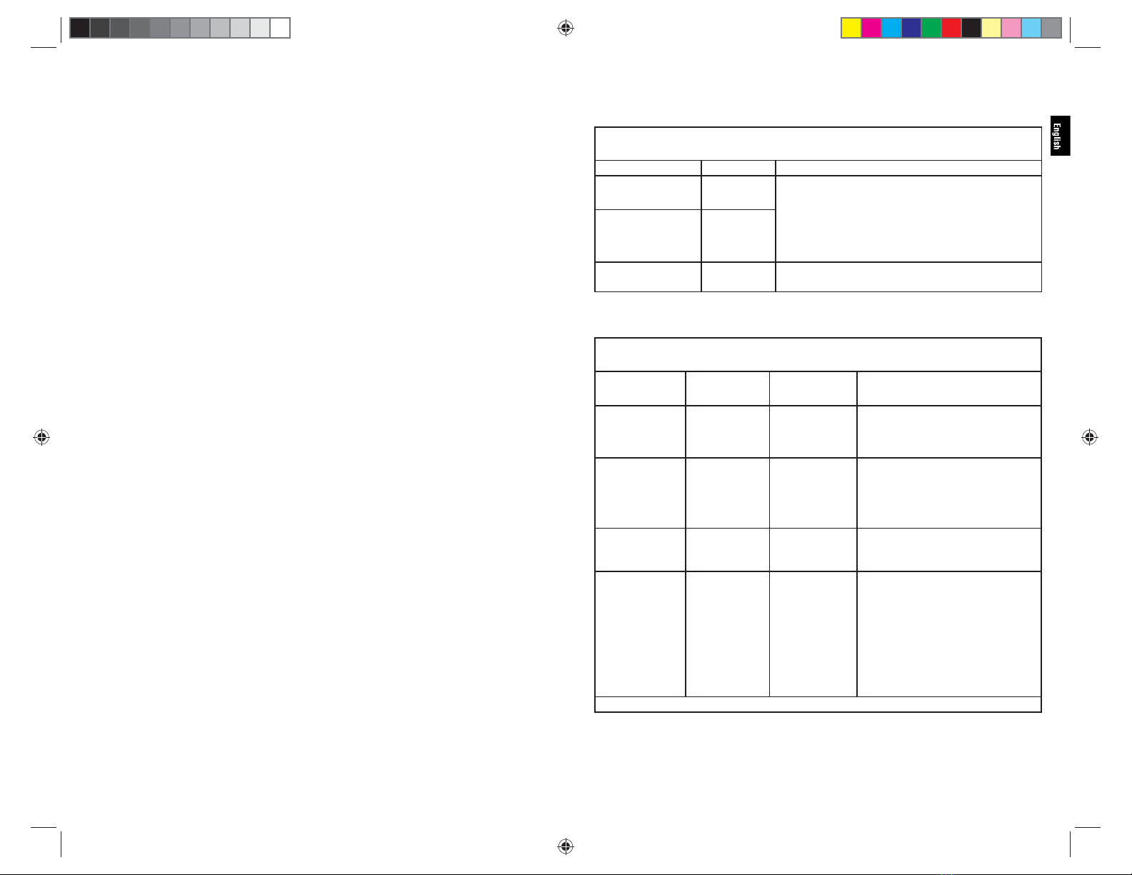
1Sicherstellen, dass die Magazingröße mit der Instrumentengröße übereinstimmt (z. B. ein ECHELON 60 Magazin nur mit einem
ECHELON 60 Instrument verwenden).
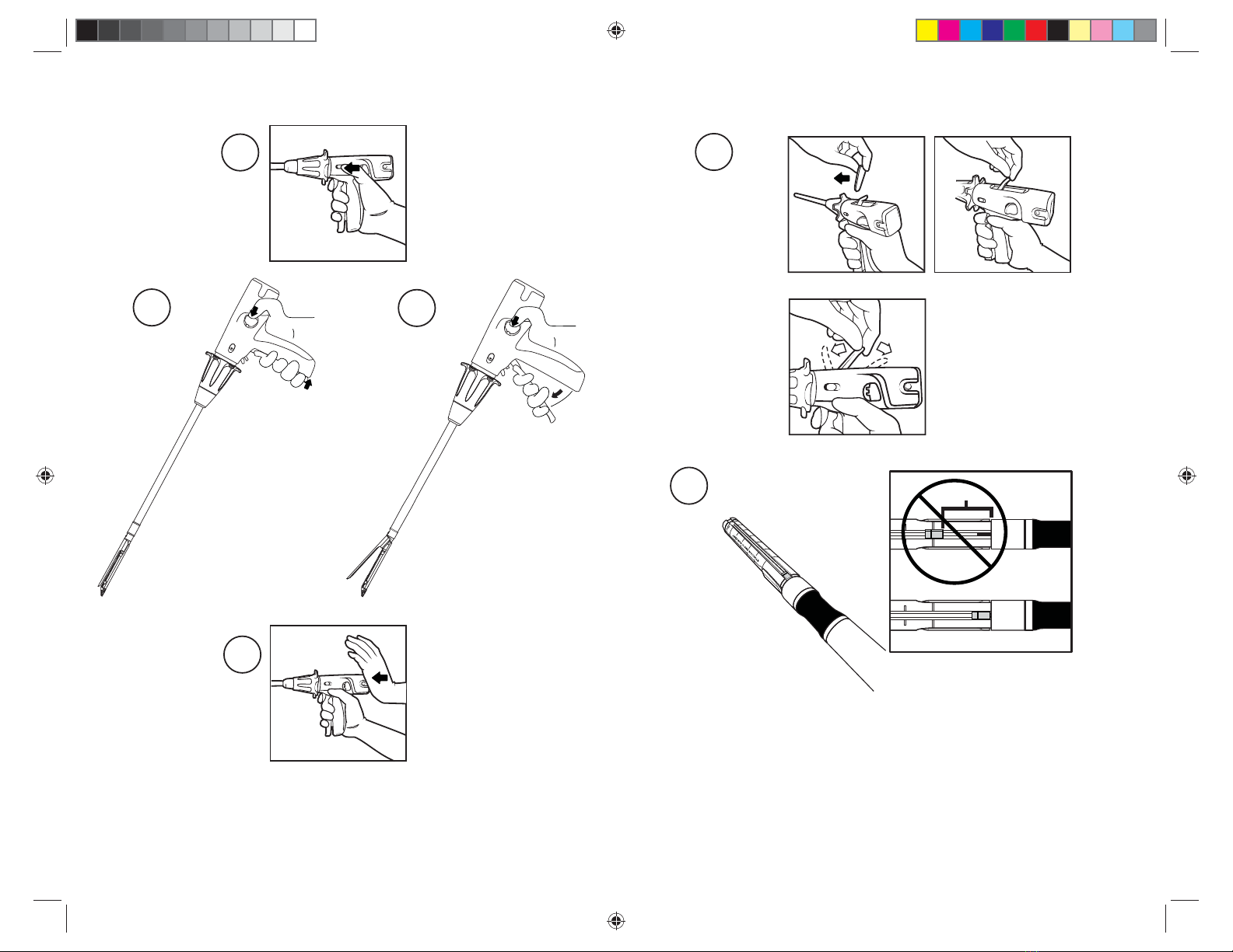
2Mit dem Zeigefinger an der Einstellvorrichtung des Drehgriffs ziehen und das Instrumentenmaul mit der anderen Hand abwinkeln (Abbildung 2),
um sich mit dem Gelenkmechanismus des Instruments vertraut zu machen. Wenn in beliebiger Richtung lateraler Druck ausgeübt wird, lässt
sich das Instrumentenmaul auf bis zu maximal 45° abwinkeln. An dieser Stelle nimmt der Kraftaufwand zu, woran zu erkennen ist, dass die
maximale Abwinkelung erreicht wurde. Den lateralen Druck aufrechterhalten und dabei den Drehgriff loslassen, um den Winkel zu fixieren.
Nachdem Magazinlager und Gegenlager fixiert wurden, den lateralen Druck aufheben. Das Instrumentenmaul wird außerdem bei ca. 15 und
30 Grad fixiert, wenn der Drehgriff losgelassen wird, bevor das Instrument ganz abgewinkelt wurde. Um das Instrumentenmaul wieder zu
begradigen, an der Einstellvorrichtung des Drehgriffs ziehen, um so die Fixierung zu lösen. Magazinlager und Gegenlager kehren automatisch
in die Ausgangsposition zurück.
3Vor Gebrauch des Instruments ist die Kompatibilität aller Instrumente sowie des Zubehörs zu überprüfen (siehe Warnungen und
Vorsichtsmaßnahmen).
Vorbereitung des Instruments
4Instrument, Batterie und Magazin in steriler Technik den Verpackungen entnehmen. Nicht in „Peeling“-Technik auf das sterile Feld des
Instrumententisches werfen, um Beschädigungen zu vermeiden.
5Vor Verwendung des Instruments die Batterie einsetzen. Hierzu müssen die Entriegelungsknöpfe an der Batterie mit den Aussparungen des
Batteriefachs auf der Rückseite des Instruments ausgerichtet sein (Abbildung 3). Sicherstellen, dass die Batterie vollständig in das Gerät
eingesetzt ist. Die Batterie sollte hörbar einrasten.
Hinweis: Das Instrument muss innerhalb von 12 Stunden nach Einsetzen der Batterie verwendet werden. Für Anweisungen zur Entsorgung
der Batterie ist der Abschnitt Entsorgung der Batterie zu beachten.
6Vor dem Einsetzen des Magazins sicherstellen, dass das Instrument geöffnet ist (Abbildung 1).
7Das Magazin auf Vorhandensein eines Klammerschutzes überprüfen. Fehlt dieser, so ist das Magazin zu entsorgen.
Achtung: Die Gewebedicke sollte sorgfältig überprüft werden, bevor das Instrument eingesetzt wird. Zur Auswahl des korrekten
Magazins ist die Tabelle mit den Bestell-Nummern der Magazine zu beachten.
Achtung: Die Auswahl eines neuen Magazins sollte sowohl von der Gewebestärke als auch von der Dicke der Nahtwiderlager abhängig
gemacht werden. Bei Einsatz in Verbindung mit Nahtwiderlagern kann ein erhöhter Kraftaufwand beim Schließen des Instruments erforderlich
sein. Auch ist das Instrument eventuell nicht so oft nachladbar. Bei Hinzuziehen von Nahtwiderlagern ist die Gebrauchsanweisung des Herstellers
zu beachten.
8Das Magazin in das Magazinlager einlegen, bis der Führungszapfen in der Zapfenverriegelung einrastet. Anschließend Klammerschutz
entfernen und entsorgen. (Abbildung 4) Das Instrument ist nun geladen und einsatzbereit.
Achtung: Nach Entfernen des Klammerschutzes ist die Oberfläche des neuen Magazins zu überprüfen. Sind anstelle der Klammern die
farbigen Klammertreiber sichtbar, muss das Magazin durch ein neues ersetzt werden. (Wenn die farbigen Klammertreiber sichtbar sind,
ist das Magazin unzureichend mit Klammern beladen.)
Handhabung des Instruments
9Magazinlager und Gegenlager durch vollständiges Heranziehen des Verschlusshebels an den Instrumentengriff schließen (Abbildung 5).
Ein hörbares Klicken zeigt an, dass der Verschlusshebel und das Instrumentenmaul geschlossen sind. Wenn das Instrumentenmaul
geschlossen ist, sind die rote Sperre des Auslöseschalters und der Auslöseschalter zugänglich.
Hinweis: Zu diesem Zeitpunkt nicht die rote Sperre des Auslöseschalters oder den Auslöseschalter betätigen. Das Instrument wurde
möglicherweise bereits teilweise oder vollständig ausgelöst und muss vor dem Einsatz am Gewebe neu geladen werden.
10 Sicherstellen, dass das Magazin korrekt in das Instrument eingesetzt wurde. Instrument über einen geeigneten Trokar oder eine Inzision
in den Körper einführen (Abbildung 6). Bei Verwendung eines Trokars müssen das Instrumentenmaul die Trokarhülse sichtbar passiert
haben, bevor es geöffnet wird.
Achtung: Zum Einführen und Entfernen der abwinkelbaren Instrumente muss das Instrumentenmaul gerade und parallel zum Schaft des
Instruments ausgerichtet sein. Andernfalls lässt sich das Instrument schwer einführen oder entfernen und könnte beschädigt werden.
Achtung: Beim Einführen des Instruments über einen Trokar oder eine Inzision nicht versehentlich die rote Sperre des Auslöseschalters oder
den Auslöseschalter betätigen. Das Instrument wurde möglicherweise bereits teilweise oder vollständig ausgelöst und muss vor dem Einsatz
am Gewebe neu geladen werden. Wurde der Auslösevorgang nicht vollständig durchgeführt, muss das Instrument entfernt und der Knopf
zum Zurückziehen der Schneidklinge nach vorne geschoben werden, um die Schneideklinge wieder in die Ausgangsposition zu bringen
(Abbildung 7). Zum Öffnen des Instrumentenmauls den Verschlusshebel an den Griff heranziehen und halten und dabei gleichzeitig einen der
sich an beiden Seiten des Instruments befindlichen Freigabeknöpfe drücken (Abbildung 8a). Während weiterhin Druck auf den Freigabeknopf
ausgeübt wird, den Verschlusshebel langsam loslassen (Abbildung 8b). Das gebrauchte Magazin durch ein neues ersetzen (siehe „Laden des
Instruments“). Nachdem das Instrument vollständig ausgelöst wurde, kehrt die Schneidklinge automatisch wieder in ihre Ausgangsposition
zurück. Das Instrument entfernen und ein neues Magazin einsetzen (siehe „Laden des Instruments“).
Hinweis: Lässst sich die Schneidklinge mit dem entsprechenden Knopf nicht in ihre Ausgangsposition zurückbringen und das
Instrumentenmaul öffnet sich nicht:
a. Zuerst sicherstellen, dass die Batterie fest eingesetzt ist und das Instrument mit Strom versorgt wird (Abbildung 9). Dann den
Knopf zum Zurückziehen der Schneidklinge erneut betätigen (Abbildung 7).
b. Wird die Schneideklinge noch immer nicht zurückgezogen, den manuellen Freigabehebel verwenden. Nachdem der Freigabehebel
verwendet wurde, ist das Instrument deaktiviert und kann nicht mehr ausgelöst werden. Zur Verwendung des manuellen Freigabehebels
die mit „Manual Override“ beschriftete Zugangsabdeckung oben am Instrumentengriff entfernen. Der manuelle Freigabehebel ist nun
zugänglich. Den Hebel bis zum Anschlag vorwärts und rückwärts bewegen. (Abbildung 10) Die Schneidklinge befindet sich nun in ihrer
Ausgangsposition, was an der Position des Schneidklingen-Indikators an der Unterseite der Gegenlagers zu erkennen ist (Abbildung 11).
Instrument entsorgen.
11 Nach Einbringen des Instruments den Verschlusshebel heranziehen und halten und dabei gleichzeitig einen der sich an beiden Seiten des
Instruments befindlichen Freigabeknöpfe drücken (Abbildung 8a). Während weiterhin Druck auf den Freigabeknopf ausgeübt wird, den
Verschlusshebel langsam loslassen, so dass er sich zurück in seine Ausgangsposition bewegt und das Instrumentenmaul geöffnet wird
(Abbildung 8b).
12 Gegebenenfalls mit dem Zeigefinger auf die Einstellvorrichtung des Drehgriffs drücken und Druck nach oben oder unten ausüben,
um das Instrumentenmaul zu drehen (Abbildung 12). Das Instrumentenmaul kann in jede Richtung gedreht werden.
13 Um das in den Körper eingeführte Instrumentenmaul abzuwinkeln, eine geeignete Oberfläche (Körperstruktur, Organ oder anderes
Instrument) als Stützfläche wählen. Dabei darauf achten, dass das Instrumentenmaul im Sichtfeld bleibt. Die laterale Seite des
Instrumentenmauls, die der gewünschten Abwinkelungsrichtung gegenüber liegt, an der Stützfläche abstützen (das Instrument kann nur
mit geöffnetem Instrumentenmaul abgewinkelt werden). (Abbildung 13)
WARNUNG: Zum Abwinkeln nicht die Vorderseite des Instrumentenmauls gegen die Stützfläche drücken, da dies zu einer Schädigung
oder einem Trauma des Gewebes führen könnte (Abbildung 14).
Mit dem Zeigefinger an der Einstellvorrichtung des Drehgriffs ziehen und eine schwungvolle Bewegung zu der Seite machen, zu der das
Instrument abgewinkelt werden soll; dabei den Instrumentengriff behutsam gegen die Stützfläche drücken. Während dieses Schritts das
Instrumentenmaul gegen die Stützfläche gedrückt lassen. Nachdem die gewünschte Abwinklung erreicht wurde, den Drehgriff loslassen,
um den Winkel zu fixieren (das Instrument kann nur in bestimmten Winkeln fixiert werden – 15º, 30º und 45º).
Achtung: Das Instrument kann maximal um 45º abgewinkelt werden. Wenn Körperstrukturen oder Organe als Stützfläche verwendet
werden, sollte besonders auf visuelle Hinweise geachtet werden und wie sich das Instrument anfühlt. An einem erhöhten Kraftaufwand
ist zu erkennen, dass die maximale Abwinklung erreicht ist. Keinen übermäßigen Druck auf das Gewebe ausüben, da dies zu einer
Schädigung oder einem Trauma des Gewebes führen könnte.
14 Instrument auf dem zu klammernden Gewebe positionieren.
Achtung: Sicherstellen, dass das Gewebe flach zwischen Magazinlager und Gegenlager liegt und richtig ausgerichtet ist. Eine
Anhäufung von Gewebe am Magazin, insbesondere an der Gabelung von Magazinlager und Gegenlager, kann zu einer unvollständigen
Klammernahtreihe führen.
Die distalen schwarzen Linien am Instrumentenmaul zeigen die beiden Enden der Klammernahtreihe an. Die Linie am Magazinlager mit
der Bezeichnung „cut“ bezieht sich auf die Schnittlänge des Instruments. (Abbildung 1)
Achtung: Beim Positionieren des Instruments am Applikationssitus ist darauf zu achten, dass sich keine Clips, Stents, Führungsdrähte
usw. zwischen Gegenlager und Magazinlager befinden. Dies könnte beim Auslösen zu einem unvollständigen Durchtrennen von Gewebe
und einer mangelhaften Klammerformung führen. Eventuell lassen sich das Instrumentenmaul auch nicht öffnen.
15 Instrumentenmaul in die entsprechende Position zum Gewebe bringen und durch vollständiges Heranziehen des Verschlusshebels an
den Griff schließen (Abbildung 5). Ein hörbares Klicken zeigt an, dass das Instrument geschlossen ist. Wenn das Instrumentenmaul
geschlossen ist, sind die rote Sperre des Auslöseschalters und der Auslöseschalter zugänglich.
Achtung: Sicherstellen, dass sich kein Gewebe hinter der proximalen schwarzen Linie am Instrument befindet (Abbildung 1), da Gewebe,
das proximal zur schwarzen Markierung zu liegen kommt, möglicherweise nur durchtrennt und nicht geklammert wird.
Achtung: Lässt sich der Verschlusshebel nur schwer schließen, ist das Instrument neu zu positionieren und weniger Gewebe zu
fassen. Sicherstellen, dass ein geeignetes Magazin ausgewählt wurde. (Siehe Tabelle mit den Bestell-Nummern der Magazine.)
Achtung: Sollte sich das Instrumentenmaul nicht korrekt schließen lassen, darf das Instrument nicht ausgelöst werden. Das Instrument
entfernen und nicht mehr verwenden.
Achtung: Wird das Instrument in Verbindung mit Nahtwiderlagern eingesetzt, kann ein erhöhter Kraftaufwand beim Schließen des
Instruments erforderlich sein. Bei Hinzuziehen von Nahtwiderlagern ist die Gebrauchsanweisung des Herstellers zu beachten.
Hinweis: Beim Auslösen an starkem Gewebe kann eine bessere Kompression und Klammerausrichtung erreicht werden, wenn das Gewebe
nach dem Schließen und vor dem Auslösen 15 Sekunden lang im Instrumentenmaul gehalten wird.
16 Die rote Sperre des Auslöseschalters zurückziehen, so dass der Auslöseschalter betätigt werden kann (Abbildung 15).
17 Auslösevorgang durch Betätigen des Auslöseschalters initiieren. Der Motor wird hörbar aktiviert (Abbildung 16). Den Auslöseschalter
weiter halten, bis der Motor hörbar stoppt, um die Durchtrennung zu Ende zu führen.
Achtung: Da der Motor auch stoppen kann, wenn das Instrument steckenbleibt, muss sichergestellt werden, dass der Schneidklingen-
Indikator an der Unterseite des Gegenlagers das Ende der Durchtrennung erreicht hat.
Achtung: Wird das Instrument mit zu viel Gewebe oder starkem Gewebe im Instrumentenmaul gewaltsam ausgelöst, kann der Motor
und damit die Schneidklinge zum Stillstand kommen. In diesem Fall den Auslöseschalter loslassen, den Knopf zum Zurückziehen der
Schneidklinge nach vorn schieben und das Instrument entfernen und neu laden (Abbildung 7). Dann mit dem Instrument weniger Gewebe
fassen oder ein Magazin verwenden, das besser geeignet ist (siehe Tabelle mit den Bestell-Nummern der Magazine).
Hinweis: Der Motor läuft langsamer, wenn mehr Kraft auf das Instrument ausgeübt wird.
18 Zum Beenden des Auslösevorgangs den Auslöseschalter loslassen, um den Motor zu aktivieren und die Schneidklinge automatisch in die
Ausgangsposition zurückzubringen, wo der Motor dann stoppt. In dieser Position ist das Instrument gesperrt, bis das Instrumentenmaul
geöffnet und wieder geschlossen wird.
Hinweis: Wenn der Auslösevorgang unterbrochen werden muss oder versehentlich durch Loslassen des Auslöseschalters unterbrochen
wird, den Auslöseschalter erneut betätigen, um fortzufahren. Der Status der Durchtrennung ist während des Auslösevorgangs an dem
Schneidklingen-Indikator an der Unterseite des Instrumentenmauls angezeigt zu erkennen (Abbildung 1). Der Vorgang kann so oft wie
nötig unterbrochen werden, bis die Schneidklinge das Gewebe vollständig durchtrennt hat. Wird der Auslöseschalter an dieser Stelle
losgelassen, kehrt die Schneidklinge automatisch in die Ausgangsposition zurück.
Achtung: Wenn die Sicherheitsautomatik aktiviert wird, stoppt der Motor. Den Auslöseschalter loslassen und den Knopf zum
Zurückziehen der Schneidklinge nach vorn schieben, um die Schneidklinge in ihre Ausgangsposition zu bringen (Abbildung 7). In dieser
Position sollte das Instrument entfernt, geöffnet und neu geladen werden, damit der Vorgang fortgesetzt werden kann. Zum Öffnen des
Instrumentenmauls den Verschlusshebel an den Griff heranziehen und halten und dabei gleichzeitig einen der sich an beiden Seiten des
Instruments befindlichen Freigabeknöpfe drücken (Abbildung 8a). Während weiterhin Druck auf den Freigabeknopf ausgeübt wird,
den Verschlusshebel langsam loslassen (Abbildung 8b). Die Handhabungsschritte zum Laden des Instruments befolgen.
Hinweis: Lässt sich die Schneidklinge mit dem entsprechenden Knopf nicht in ihre Ausgangsposition zurückbringen und das
Instrumentenmaul öffnet sich nicht:
a. Zuerst sicherstellen, dass die Batterie fest eingesetzt ist und das Instrument mit Strom versorgt wird (Abbildung 9). Dann den
Knopf zum Zurückziehen der Schneidklinge erneut betätigen (Abbildung 7).
b. Wird die Schneideklinge noch immer nicht zurückgezogen, den manuellen Freigabehebel verwenden.
Achtung: Nachdem der manuelle Freigabehebel verwendet wurde, ist das Instrument deaktiviert und kann nicht mehr ausgelöst
werden.
Zur Verwendung des manuellen Freigabehebels die mit „Manual Override“ beschriftete Zugangsabdeckung oben am
Instrumentengriff entfernen. Der manuelle Freigabehebel ist nun zugänglich. Den Hebel bis zum Anschlag vorwärts und rückwärts
bewegen. (Abbildung 10) Die Schneidklinge befindet sich nun in ihrer Ausgangsposition, was an der Position des Schneidklingen-
Indikators an der Unterseite des Gegenlagers zu erkennen ist (Abbildung 11). Instrument entsorgen.
Achtung: Ein unvollständiges Auslösen könnte zu einer mangelhaften Klammerformung, zu einer unvollständigen Durchtrennung,
Blutungen und/oder Schwierigkeiten beim Entfernen des Instruments führen.
Achtung: Bei Einsatz in Verbindung mit Nahtwiderlagern sind die Instrumente eventuell nicht so oft nachladbar. Bei Hinzuziehen von
Nahtwiderlagern ist die Gebrauchsanweisung des Herstellers zu beachten.
Hinweis: Das Auslösen des Instruments über einer bereits gesetzten Klammernahtreihe kann die Lebensdauer des Instruments verkürzen.
Achtung: Wenn der Auslösemechanismus nicht funktioniert, darf das Instrument nicht noch einmal zum Einsatz kommen.
19 Zum Öffnen des Instrumentenmauls den Verschlusshebel an den Griff heranziehen und halten und dabei gleichzeitig einen der sich an
beiden Seiten des Instruments befindlichen Freigabeknöpfe drücken. Während weiterhin Druck auf den Freigabeknopf ausgeübt wird,
den Verschlusshebel langsam loslassen. (Abbildung 8)
A88091P00 AMP IFU_1_18_12.indd 30-31A88091P00 AMP IFU_1_18_12.indd 30-31 1/18/12 9:29 AM1/18/12 9:29 AM

32 33
Achtung: Sollte sich das Instrumentenmaul nach Betätigen des Freigabeknopfs nicht automatisch öffnen, muss zunächst überprüft werden,
ob sich die Schneidklinge in der Ausgangsposition befindet. Die Position der Schneidklinge ist an dem Schneidklingen-Indikator an der
Unterseite des Instrumentenmauls zu erkennen. (Abbildung 11) Wenn sich der Schneidklingen-Indikator nicht in der Ausgangsposition befindet
oder die Position der Schneidklinge nicht zu erkennen ist, den Knopf zum Zurückziehen der Schneidklinge nach vorn schieben. Dadurch wird
der Motor aktiviert und die Schneidklinge in ihre Ausgangsposition gebracht (Abbildung 7). Erneut versuchen, das Instrumentenmaul mit
dem Freigabeknopf zu öffnen. Sollte sich das Instrumentenmaul dadurch nicht öffnen, muss der Verschlusshebel (1) manuell nach oben
(vom Instrumentengriff weg) gedrückt werden, bis Verschlusshebel und Auslöseschalter in ihre Ausgangsposition zurückkehren.
20 Das Instrument behutsam von dem durchtrennten Gewebe wegziehen und sicherstellen, dass das Gewebe vollständig von dem
Instrumentenmaul freigegeben wurde.
Achtung: Anschließend die Klammernahtreihen auf Hämostase, Luftdichtigkeit und vollständige Klammerformung überprüfen. Schwache
Blutungen können mit manuell gelegten Nähten oder anderen angemessenen Methoden kontrolliert werden.
21 Vor Entfernen der abwinkelbaren Instrumente ist darauf zu achten, dass das Instrumentenmaul offen und frei beweglich ist und sich stets
innerhalb des Blickfelds befindet. An der Einstellvorrichtung des Drehgriffs ziehen. Das Instrumentenmaul kehrt automatisch in die gerade
Ausgangsposition zurück.
Achtung: Zum Einführen und Entfernen der abwinkelbaren Instrumente muss das Instrumentenmaul gerade und parallel zum Schaft des
Instruments sein. Ist dies nicht der Fall, kann das Einführen oder Entfernen des Instruments mit erheblichen Schwierigkeiten verbunden
sein und es besteht die Gefahr, dass das Instrument beschädigt wird.
22 Zum Entfernen des Instruments wird das Instrumentenmaul durch vollständiges Heranziehen des Verschlusshebels an den Griff
geschlossen (Abbildung 5). Geschlossenes Instrument vollständig entfernen.
Laden des Instruments
23 Magazin in steriler Technik der Verpackung entnehmen. Nicht in „Peeling“-Technik auf das sterile Feld des Instrumententisches werfen,
um Beschädigungen zu vermeiden.
24 Vor dem Laden sicherstellen, dass das Instrument geöffnet ist (Abbildung 1).
25 Leeres Magazin nach oben drücken (zum Gegenlager hin), bis es sich aus dem Magazinlager löst (Abbildung 17). Gebrauchtes Magazin
entsorgen.
WARNUNG: Das Instrument vor dem Nachladen senkrecht halten und Gegenlager und Magazinlager vollständig in eine sterile Lösung tauchen.
Die Innen- und Außenflächen von Gegenlager und Magazinlager auswaschen und spülen, um unbenutzte Klammern zu entfernen. Das Instrument
darf erst eingesetzt werden, nachdem sichergestellt wurde, dass sich keine Klammern im Bereich des Instrumentenmauls befinden.
26 Das neue Magazin auf Vorhandensein eines Klammerschutzes überprüfen. Fehlt dieser, so ist das Magazin zu entsorgen.
Achtung: Die Gewebedicke sollte sorgfältig überprüft werden, bevor das Instrument eingesetzt wird. Zur Auswahl des korrekten
Magazins ist die Tabelle mit den Bestell-Nummern der Magazine zu beachten.
Achtung: Die Auswahl eines neuen Magazins sollte sowohl von der Gewebestärke als auch von der Dicke der Nahtwiderlager
abhängig gemacht werden. Bei Einsatz in Verbindung mit Nahtwiderlagern kann ein erhöhter Kraftaufwand beim Schließen des
Instruments erforderlich sein. Auch ist das Instrument eventuell nicht so oft nachladbar. Bei Hinzuziehen von Nahtwiderlagern ist die
Gebrauchsanweisung des Herstellers zu beachten.
27 Das neue Magazin in das Magazinlager einschieben, bis der Führungszapfen in der Zapfenverriegelung einrastet. Anschließend
Klammerschutz entfernen und entsorgen. Das Instrument ist nun nachgeladen und einsatzbereit (Abbildung 4).
Achtung: Nach Entfernen des Klammerschutzes ist die Oberfläche des neuen Magazins zu überprüfen. Sind anstelle der Klammern die
farbigen Klammertreiber sichtbar, muss das Magazin durch ein neues ersetzt werden. (Wenn die farbigen Klammertreiber sichtbar sind,
ist das Magazin unzureichend mit Klammern beladen.)
Entsorgung der Batterie
Die integrierte Batterieentleerungsfunktion wird beim Einsetzen der Batterie in das Instrument automatisch aktiviert und auch nach dem
Entfernen aus dem Instrument fortgesetzt. Die entfernte Batterie kann gemäß den entsprechenden örtlichen Vorschriften direkt in einem Batterie-
Recycling-Behälter oder als Teil der normalen Abfallbeseitigung entsorgt werden.
Vor dem Einsetzen in ein Instrument
Falls eine noch nicht in das Instrument eingesetzte Batterie entsorgt werden muss (z. B. bei Überschreiten des auf der Batterie
angegebenen Ablaufdatums oder bei Fallenlassen der Batterie), die Batterie zuerst in das Instrument einsetzen und dann wieder entfernen,
um die integrierte Batterieentleerungsfunktion zu aktivieren.
Nach der Verwendung im Instrument
Die Batterie muss vor der Entsorgung aus dem Instrument entfernt werden.
Wenn die Batterie vor der Entsorgung dekontaminiert werden muss, das Protokoll des Krankenhauses oder die nachstehenden Anweisungen unter
Reinigung und Desinfektion der Batterie befolgen.
Zur Entnahme der Batterie auf die Entriegelungsknöpfe an der Batterie drücken und die Batterie gerade nach hinten aus dem Batteriefach am
Instrument herausziehen (Abbildung 18).
Hinweis: Der Batteriesatz muss nicht auseinandergenommen werden.
Reinigung und Desinfektion der Batterie
WARNUNG: Die Batterie darf nicht mit dem Autoklaven des Krankenhauses sterilisiert oder desinfiziert werden.
Manuelle Reinigung
1Die Batterie vor der Reinigung aus dem Instrument nehmen.
Hinweis: Die Batterie darf nicht in Wasser oder Reinigungslösungen getaucht werden.
2Die Oberflächen der Batterie mit einem gemäß den Anweisungen des Herstellers zubereiteten ph-neutralen oder ph-neutralen
enzymatischen Reinigungsmittel reinigen.
3Die Batterie mit einer weichen Bürste von Hand mit Reinigungslösung reinigen.
4Bereiche mit Spalten besonders gründlich abbürsten.
5Das Reinigungsmittel mit lauwarmem Leitungswasser gründlich abwischen.
6 Sicherstellen, dass alle Rückstände entfernt wurden.
7 Die Reinigung ggf. wiederholen, bis die Batterie sauber ist.
Chemische Desinfektion
Die Reinigungsmittel sollten gemäß den Angaben des Herstellers zubereitet und angewandt werden. Es wird empfohlen, chemische Desinfektionsmittel
mit Leitungswasser abzuwischen.
• Simple Green D Pro 3®
• 10 %iges Bleichmittel (Natriumhypochlorit)
• 70 %iger Isopropylalkohol
Verwendete Standardkonventionen
Mit„Achtung“,„Warnung“ und„Hinweis“ eingeleitete Erklärungen
Informationen bezüglich der sicheren Durchführung einer Aufgabe werden durch „Achtung“, „Warnung“ oder „Hinweis“ ausgewiesen. Diese
Erklärungen sind durchweg in der Dokumentation zu finden.
Diese Anweisungen sollten gelesen werden, bevor mit dem nächsten Schritt fortgefahren wird.
WARNUNG: Eine mit „Warnung“ gekennzeichnete Erklärung weist auf ein Betriebs- oder Wartungsverfahren, eine Vorgehensweise oder eine
Bedingung hin, die bei Nichteinhaltung zu Körperverletzung oder zum Tode führen könnte.
Achtung: Eine mit „Achtung“ gekennzeichnete Erklärung weist auf ein Betriebs- oder Wartungsverfahren, eine Vorgehensweise oder eine
Bedingung hin, die zu einer Beschädigung oder Zerstörung von Geräten führen könnte.
Hinweis: Eine mit „Hinweis“ gekennzeichnete Erklärung weist auf ein Problem bei Betrieb oder Wartung, eine Vorgehensweise oder eine
Bedingung hin, die zur effizienten Ausführung der Aufgabe beachtet werden muss.
Warnungen und Vorsichtsmaßnahmen
• Minimal-invasive Eingriffe sind ausschließlich von mit minimal-invasiven Verfahren vertrauten Personen vorzunehmen.
• Der Durchmesser minimal-invasiver Instrumente kann von Hersteller zu Hersteller unterschiedlich sein. Werden minimal-invasive
Instrumente und Zubehörteile verschiedener Hersteller bei einem Eingriff gleichzeitig eingesetzt, ist vor OP-Beginn darauf zu achten,
dass die Produkte kompatibel sind.
• Kommen bei dem Verfahren noch andere Technologien (z. B. Elektrochirurgie) zum Einsatz, sind die vom ursprünglichen Hersteller
angegebenen Vorsichtsmaßnahmen zu beachten, um etwaige hiermit verbundenen Gefahren zu vermeiden.
• Nicht ordnungsgemäße Anwendung kann zu ernsthaften chirurgischen Komplikationen, wie z. B. Leckagen oder einer unvollständigen
Klammernahtreihe, führen.
• Die Instrumente können während eines Eingriffs bis zu zwölfmal geladen und somit zwölfmal bei einem Patienten eingesetzt werden.
Bei Einsatz in Verbindung mit Nahtwiderlagern sind die Instrumente eventuell nicht so oft nachladbar.
• Die ECHELON FLEX Instrumente dürfen nur zusammen mit ECHELON Magazinen eingesetzt werden.
• Die Gewebedicke sollte sorgfältig überprüft werden, bevor eine Klammer abgesetzt wird. Zur Auswahl des korrekten Magazins auf die
Tabelle mit den Bestell-Nummern der Magazine Bezug nehmen.
• Die Auswahl eines neuen Magazins sollte sowohl von der Gewebestärke als auch von der Dicke der Nahtwiderlager abhängig gemacht
werden. Bei Einsatz in Verbindung mit Nahtwiderlagern kann ein erhöhter Kraftaufwand beim Schließen des Instruments erforderlich
sein. Auch ist das Instrument eventuell nicht so oft nachladbar. Bei Hinzuziehen von Nahtwiderlagern ist die Gebrauchsanweisung des
Herstellers zu beachten.
• Nach Entfernen des Klammerschutzes ist die Oberfläche des neuen Magazins zu überprüfen. Sind anstelle der Klammern die farbigen
Klammertreiber sichtbar, muss das Magazin durch ein neues ersetzt werden. (Wenn die farbigen Klammertreiber sichtbar sind, ist das
Magazin unzureichend mit Klammern beladen.)
• Zum Einführen und Entfernen der abwinkelbaren Instrumente muss das Instrumentenmaul gerade und parallel zum Schaft des Instruments
sein. Andernfalls lässt sich das Instrument schwer einführen oder entfernen und könnte beschädigt werden.
• Beim Einführen des Instruments über einen Trokar oder eine Inzision nicht versehentlich die rote Sperre des Auslöseschalters oder den
Auslöseschalter betätigen. Das Instrument wurde möglicherweise bereits teilweise oder vollständig ausgelöst und muss vor dem Einsatz
am Gewebe neu geladen werden.
• Zum Abwinkeln nicht die Vorderseite des Instrumentenmauls gegen die Stützfläche drücken, da dies zu einer Schädigung oder einem
Trauma des Gewebes führen könnte.
• Das Instrument kann maximal um 45º abgewinkelt werden. Wenn Körperstrukturen oder Organe als Stützfläche verwendet werden, sollte
besonders auf visuelle Hinweise geachtet werden, und wie sich das Instrument anfühlt. An einem erhöhten Kraftaufwand ist zu erkennen,
dass die maximale Abwinklung erreicht ist. Keinen übermäßigen Druck auf das Gewebe ausüben, da dies zu einer Schädigung oder einem
Trauma des Gewebes führen könnte.
• Sicherstellen, dass das Gewebe flach zwischen Magazinlager und Gegenlager liegt und richtig ausgerichtet ist. Eine Anhäufung von Gewebe
am Magazin, insbesondere an der Gabelung von Magazinlager und Gegenlager, kann zu einer unvollständigen Klammernahtreihe führen.
• Beim Positionieren des Instruments am Applikationssitus ist darauf zu achten, dass sich keine Clips, Stents, Führungsdrähte usw. zwischen
Gegenlager und Magazinlager befinden. Dies könnte beim Auslösen zu einem unvollständigen Durchtrennen von Gewebe und einer
mangelhaften Klammerformung führen. Eventuell lässt sich das Instrumentenmaul auch nicht öffnen.
• Sicherstellen, dass sich kein Gewebe hinter der proximalen schwarzen Linie am Instrument befindet, da Gewebe, das proximal zur
schwarzen Markierung zu liegen kommt, möglicherweise nur durchtrennt und nicht geklammert wird.
• Lässt sich der Verschlusshebel nur schwer schließen, ist das Instrument neu zu positionieren und weniger Gewebe zu fassen.
Sicherstellen, dass ein geeignetes Magazin ausgewählt wurde. (Siehe Tabelle mit den Bestell-Nummern der Magazine.)
• Sollte sich das Instrumentenmaul nicht korrekt schließen lassen, darf das Instrument nicht ausgelöst werden. Das Instrument entfernen und
nicht mehr verwenden.
• Bei Einsatz in Verbindung mit Nahtwiderlagern kann ein erhöhter Kraftaufwand beim Schließen des Instruments erforderlich sein.
Bei Hinzuziehen von Nahtwiderlagern ist die Gebrauchsanweisung des Herstellers zu beachten.
• Wird das Instrument mit zu viel Gewebe oder starkem Gewebe im Instrumentenmaul gewaltsam ausgelöst, kann der Motor und damit die
Schneidklinge zum Stillstand kommen.
A88091P00 AMP IFU_1_18_12.indd 32-33A88091P00 AMP IFU_1_18_12.indd 32-33 1/18/12 9:29 AM1/18/12 9:29 AM

34 35
• Da der Motor auch stoppen kann, wenn das Instrument steckenbleibt, muss sichergestellt werden, dass der Schneidklingen-Indikator an der
Unterseite des Gegenlagers das Ende der Durchtrennung erreicht hat.
• Wenn die Sicherheitsautomatik aktiviert wird, stoppt der Motor. Den Auslöseschalter loslassen und den Knopf zum Zurückziehen der
Schneidklinge nach vorn schieben, um die Schneidklinge in ihre Ausgangsposition zu bringen. In dieser Position sollte das Instrument
entfernt, geöffnet und neu geladen werden, damit der Vorgang fortgesetzt werden kann.
• Nachdem der manuelle Freigabehebel verwendet wurde, ist das Instrument deaktiviert und kann nicht mehr ausgelöst werden.
• Ein unvollständiges Auslösen könnte zu einer mangelhaften Klammerformung, zu einer unvollständigen Durchtrennung, Blutungen und/
oder Schwierigkeiten beim Entfernen des Instruments führen.
• Wenn der Auslösemechanismus nicht funktioniert, darf das Instrument nicht noch einmal zum Einsatz kommen.
• Sollte sich das Instrumentenmaul nach Betätigen des Freigabeknopfs nicht automatisch öffnen, muss zunächst überprüft werden, ob sich
die Schneidklinge in der Ausgangsposition befindet. Die Position der Schneidklinge ist an dem Schneidklingen-Indikator an der Unterseite
des Instrumentenmauls zu erkennen. Wenn sich der Schneidklingen-Indikator nicht in der Ausgangsposition befindet oder die Position
der Schneidklinge nicht zu erkennen ist, den Knopf zum Zurückziehen der Schneidklinge nach vorn schieben. Dadurch wird der Motor
aktiviert und die Schneidklinge in ihre Ausgangsposition gebracht (Abbildung 7). Erneut versuchen, das Instrumentenmaul mit dem
Freigabeknopf zu öffnen. Sollte sich das Instrumentenmaul dadurch nicht öffnen, muss der Verschlusshebel (1) manuell nach oben
(vom Instrumentengriff weg) gedrückt werden, bis Verschlusshebel und Auslöseschalter in ihre Ausgangsposition zurückkehren.
• Anschließend die Klammernahtreihen auf Hämostase, Luftdichtigkeit und vollständige Klammerformung überprüfen. Schwache
Blutungen können mit manuell gelegten Nähten oder anderen angemessenen Methoden kontrolliert werden.
• Das Instrument vor dem Nachladen senkrecht halten und Gegenlager und Magazinlager vollständig in eine sterile Lösung eintauchen. Die Innen-
und Außenflächen von Gegenlager und Magazinlager auswaschen und spülen, um unbenutzte Klammern zu entfernen. Das Instrument darf erst
eingesetzt werden, nachdem sichergestellt wurde, dass sich keine Klammern im Bereich des Instrumentenmauls befinden.
• Vor Entfernen des Instruments ist das Instrumentenmaul vom Gewebe zu lösen und dann zu schließen.
• Bei der Auswahl des Magazins sollten bestehende Krankheitszustände sowie vor dem chirurgischen Eingriff erfolgte Behandlungen,
wie z. B. Bestrahlungen, sorgfältig berücksichtigt werden. Bestimmte Zustände oder präoperative Behandlungen können bewirken,
dass die geänderte Gewebestärke den Bereich überschreitet, der als Standardwahl für das Magazin angegeben wird.
• Beim Durchtrennen von Hauptgefäßen sind die grundlegenden chirurgischen Prinzipien der proximalen und distalen Kontrolle
zu beachten.
• Die Batterie darf nicht mit dem Autoklaven des Krankenhauses sterilisiert oder desinfiziert werden.
• Die Verwendung einer anderen Art von Batterie als die mit dem Instrument gelieferte Batterie kann zu erhöhten EMISSIONEN oder
verringerter STÖRFESTIGKEIT des ECHELON FLEX Powered abwinkelbaren endoskopischen Linear Cutter führen.
• Tragbare und mobile HF-Kommunikationsgeräte können Auswirkungen auf medizinische Geräte haben. Die Anweisungen in den
folgenden Tabellen gelten für die Anwendung der ECHELON FLEX Powered abwinkelbaren endoskopischen Linear Cutter.
• Der ECHELON FLEX Powered abwinkelbare endoskopische Linear Cutter sollte nach Möglichkeit nicht direkt neben oder über anderen
Geräten eingesetzt werden. Sollte eine derartige Verwendung dennoch notwendig sein, sind der ECHELON FLEX Powered abwinkelbare
endoskopische Linear Cutter und die anderen Geräte auf normales Betriebsverhalten zu überwachen.
• Instrumente oder Produkte, die mit Körperflüssigkeiten in Berührung kommen, bedürfen einer besonderen Entsorgung, um eine
Kontamination zu vermeiden.
• Dieses Instrument ist steril verpackt und nur für den Einsatz bei einem Patienten vorgesehen. Das Instrument nicht wiederverwenden,
aufbereiten oder resterilisieren, da hierdurch die Funktion des Instruments beeinträchtigt werden kann und/oder es zu einem Versagen des
Instruments kommen könnte. Dies wiederum kann zu einer Verletzung oder Erkrankung bzw. zum Tode des Patienten führen. Weiterhin
besteht durch eine Aufbereitung oder Resterilisation von Einweg-Instrumenten das Risiko einer Kontamination und/oder Infektion des
Patienten bzw. einer Kreuzinfektion, einschließlich, jedoch nicht beschränkt auf die Übertragung von Infektionen von einem Patienten auf
den anderen. Eine Kontamination des Instruments kann zu einer Verletzung oder Erkrankung bzw. zum Tode des Patienten führen.
Technische Daten
Der ECHELON FLEX Powered abwinkelbare endoskopische Linear Cutter hat eine Nennleistung von 40 W.
Der ECHELON FLEX Powered abwinkelbare endoskopische Linear Cutter ist eindringendem Wasser gegenüber unempfindlich und gemäß IEC
60601-1 als IPXO klassifiziert.
Der ECHELON FLEX Powered abwinkelbare endoskopische Linear Cutter erfordert besondere Vorsichtsmaßnahmen hinsichtlich der
elektromagnetischen Verträglichkeit und muss in Übereinstimmung mit den EMV-Informationen in diesem Dokument installiert und eingesetzt
werden. Tragbare und mobile HF-Kommunikationsgeräte können Auswirkungen auf medizinische Elektrogeräte haben.
WARNUNG: Die Verwendung einer anderen Art von Batterie als die mit dem Instrument gelieferte Batterie kann zu erhöhten EMISSIONEN
oder verringerter STÖRFESTIGKEIT des ECHELON FLEX Powered abwinkelbaren endoskopischen Linear Cutter führen.
WARNUNG: Tragbare und mobile HF-Kommunikationsgeräte können Auswirkungen auf medizinische Elektrogeräte haben. Die Anweisungen
in den folgenden Tabellen gelten für die Anwendung der ECHELON FLEX Powered abwinkelbaren endoskopischen Linear Cutter.
WARNUNG: Der ECHELON FLEX Powered abwinkelbare endoskopische Linear Cutter sollte nach Möglichkeit nicht direkt neben oder
über anderen Geräten eingesetzt werden. Sollte eine derartige Verwendung dennoch notwendig sein, sind der ECHELON FLEX Powered
abwinkelbare endoskopische Linear Cutter und die anderen Geräte auf normales Betriebsverhalten zu überwachen.
Hinweise zu elektromagnetischen Emissionen
Der ECHELON FLEX Powered abwinkelbare endoskopische Linear Cutter ist für den Einsatz in dem nachstehend erläuterten
elektromagnetischen Umfeld vorgesehen. Der Kunde oder der Anwender des ECHELON FLEX Powered abwinkelbaren endoskopischen
Linear Cutter muss den Einsatz in einem geeigneten Umfeld sicherstellen.
Emissionsprüfung Compliance Hinweise zur elektromagnetischen Umgebung
Harmonische Emissionen
IEC 61000-3-2 Nicht anwendbar
Spannungsschwankungen/
Flimmern
IEC 61000-3-3
Nicht anwendbar
HF-Emissionen
CISPR 14-1
Entspricht der Norm Der ECHELON FLEX Powered abwinkelbare endoskopische Linear Cutter ist
nicht zum Anschließen an andere Geräte vorgesehen.
Hinweise zur elektromagnetischen Störfestigkeit
In Hinblick auf die elektromagnetische Störfestigkeit gilt grundlegend: keine Bewegung der Schneidklinge ohne Betätigung des Auslöseschalters.
Der ECHELON FLEX Powered abwinkelbare endoskopische Linear Cutter ist für den Einsatz in dem nachstehend erläuterten
elektromagnetischen Umfeld vorgesehen. Der Kunde oder der Anwender des ECHELON FLEX Powered abwinkelbaren endoskopischen
Linear Cutters muss den Einsatz in einem geeigneten Umfeld sicherstellen.
Störfestigkeitsprüfung IEC 60601
Testebene
Compliance-Niveau Hinweise zur elektromagnetischen
Umgebung
Elektrostatische
Entladung (ESD)
IEC 61000-4-2
± 6 kV direkter Kontakt
± 8 kV Luft
± 6 kV direkter Kontakt
± 8 kV Luft
Böden sollten aus Holz, Beton oder Keramikfliesen
bestehen. Bei Kunststoffbelägen sollte die relative
Feuchtigkeit mindestens 30 % betragen.
Transiente Störsignale
(Burst)
IEC 61000-4-4
± 2 kV für
Netzstromleitungen
± 1 kV für Eingangs-/
Ausgangsleitungen
Nicht anwendbar
Stoßspannungen
IEC 61000-4-11
± 1 kV Phase gegen
Phase
± 2 kV Phase gegen
Schutzleiter
Nicht anwendbar
Spannungsschwankungen/
Flimmern
IEC 61000-3-3
<5 % UT
(>95 % Abfall UT)
für 0,5 Zyklen
40 % UT
(60 % Abfall der UT)
für 5 Zyklen
70 % UT
(30 % Abfall UT)
für 25 Zyklen
<5 % UT
(>95 % Abfall UT)
für 5 Sekunden
Nicht anwendbar
HINWEIS UT ist die Netzspannung vor Anwendung der Testebene.
A88091P00 AMP IFU_1_18_12.indd 34-35A88091P00 AMP IFU_1_18_12.indd 34-35 1/18/12 9:29 AM1/18/12 9:29 AM

36 37
Der ECHELON FLEX Powered abwinkelbare endoskopische Linear Cutter ist für den Einsatz in dem nachstehend erläuterten
elektromagnetischen Umfeld vorgesehen. Der Kunde oder der Anwender des ECHELON FLEX Powered abwinkelbaren endoskopischen
Linear Cutters muss den Einsatz in einem geeigneten Umfeld sicherstellen.
Hochfrequentes
(50/60 Hz)
elektromagnetisches Feld
IEC 61000-4-8
3 A/m 3 A/m
Hochfrequente elektromagnetische Felder
sollten denen in normalen kommerziellen oder
Krankenhausumgebungen entsprechen.
HINWEIS UT ist die Netzspannung vor Anwendung der Testebene.
Der ECHELON FLEX Powered abwinkelbare endoskopische Linear Cutter ist für den Einsatz in dem nachstehend erläuterten
elektromagnetischen Umfeld vorgesehen. Der Kunde oder der Anwender des ECHELON FLEX Powered abwinkelbaren endoskopischen
Linear Cutter muss den Einsatz in einem geeigneten Umfeld sicherstellen.
Störfestigkeitsprüfung IEC 60601Test-
ebene
Compliance-
Niveau
Hinweise zur elektromagnetischen
Umgebung
Geleitete HF
IEC 61000-4-6
Abgestrahlte HF
IEC 61000-4-3
3 Veff
150 kHz bis 80 MHz
3 V/m
80 MHz bis 2,5 GHz
Nicht anwendbar
3 V/m
Bei der Verwendung von
tragbaren und mobilen
Hochfrequenzkommunikationsgeräte
sollte der empfohlene Abstand zu
dem ECHELON FLEX Powered
abwinkelbaren endoskopischen Linear
Cutter einschließlich Kabeln eingehalten
werden. Dieser Abstand wird aus einer
der Senderfrequenz entsprechenden
Gleichung ermittelt.
Empfohlener Mindestabstand
Pd =1,2 - Nicht anwendbar
Pd =1,2 80 MHz bis 800 MHz
Pd =1,2 800 MHz bis 2,5 GHz
Wobei Pdie maximale
Ausgangsnennleistung des Senders in
Watt (W) lt. Herstellerangaben ist und d
den empfohlenen Abstand in Metern (m)
darstellt.
Die Feldstärken stationärer Funksender,
die durch eine EMV-Prüfung vor Ort
ermittelt wurden,
a
sollten in jedem
Frequenzbereich unter dem Compliance-
Niveau liegen.
b
In der Nähe von Geräten, die mit dem
folgenden Symbol gekennzeichnet sind,
können Störungen auftreten:
HINWEIS 1: Bei 80 MHz und 800 MHz gilt der Abstand für den höheren Frequenzbereich.
HINWEIS 2: Diese Richtlinien treffen u. U. nicht auf alle Situationen zu, da die Ausbreitung elektromagnetischer Wellen auch durch
Absorption und Reflexion von in der Nähe befindlichen Bauwerken, Gegenständen und Menschen beeinflusst wird.
a
Feldstärken von stationären Sendern, wie z. B. Basisstationen für Funktelefone (Handy oder kabellos) und terrestrischen Mobilfunk,
Amateurfunk, sowie amplitudenmodulierte (AM) und frequenzmodulierte (FM) Rundfunk- bzw. Fernsehsendungen können theoretisch nicht
genau abgeschätzt werden. Zur Beurteilung des elektromagnetischen Umfelds, das durch solche stationären Funksender erzeugt wird, sollte eine
EMV-Prüfung vor Ort in Betracht gezogen werden. Wenn die gemessenen Feldstärken am Standort, an dem der ECHELON FLEX Powered
abwinkelbare endoskopische Linear Cutter zum Einsatz kommt, das anwendbare, oben genannte Compliance-Niveau überschreitet, muss
überprüft werden, ob der ECHELON FLEX Powered abwinkelbare endoskopische Linear Cutter einwandfrei funktioniert. Bei abnormaler
Funktion sind entsprechende zusätzliche Maßnahmen zu treffen, so z. B. eine Neuausrichtung des ECHELON FLEX Powered abwinkelbaren
endoskopischen Linear Cutter.
b
Im Frequenzbereich von 150 kHz bis 80 MHz sollten die Feldstärken unter 3 V/m liegen.
Empfohlener Abstand zwischen tragbaren und mobilen Hochfrequenzkommunikationsgeräten
und dem ECHELON FLEX Powered abwinkelbaren endoskopischen Linear Cutter
Der ECHELON FLEX Powered abwinkelbare endoskopische Linear Cutter ist für die Verwendung in einem elektromagnetischen Umfeld
bestimmt, in dem HF-Störstrahlungen unter Kontrolle gehalten werden. Der Kunde bzw. Benutzer des ECHELON FLEX Powered
abwinkelbaren endoskopischen Linear Cutter kann zur Vermeidung elektromagnetischer Störungen beitragen, indem er den Mindestabstand
zwischen tragbaren Kommunikationsgeräten sowie mobilen HF-Funkgeräten (Sendern) und dem ECHELON FLEX Powered abwinkelbaren
endoskopischen Linear Cutter entsprechend der nachstehenden Empfehlungen einhält. Diese Empfehlungen basieren auf der maximalen
Ausgangsleistung der Kommunikationsgeräte.
Max. Ausgangsnennleistung
des Senders
W
Abstand im Verhältnis zur Senderfrequenz
m
150 kHz bis 80 MHz
Pd =1,2
80 MHz bis 800 MHz
Pd =1,2
800 MHz bis 2,5 GHz
Pd =1,2
0,01 Nicht anwendbar 0,12 0,23
0,1 Nicht anwendbar 0,37 0,74
1 Nicht anwendbar 1,17 2,33
10 Nicht anwendbar 3,69 7,38
100 Nicht anwendbar 11,67 23,33
Bei Sendern mit einer oben nicht aufgeführten maximalen Augangsnennleistung kann der empfohlene Abstand din Metern (m) durch die
der Senderfrequenz entsprechende Formel geschätzt werden, wobei Pdie vom Hersteller angegebene maximale Ausgangsnennleistung des
Senders in Watt (W) ist.
HINWEIS 1: Bei 80 MHz und 800 MHz gilt der Abstand für den höheren Frequenzbereich.
HINWEIS 2: Diese Richtlinien treffen u. U. nicht auf alle Situationen zu, da die Ausbreitung elektromagnetischer Wellen auch durch
Absorption und Reflexion von in der Nähe befindlichen Bauwerken, Gegenständen und Menschen beeinflusst wird.
Bedingungen für Transport und Lagerung
Temperatur: -22 ºC – 60 ºC
Relative Feuchte: 10 % – 80 %
Druck: 500 – 1060 hPa
Instrumentenausführung
Die ECHELON-Familien der endoskopischen Linear Cutter werden steril geliefert und sind nur für den Einsatz bei einem Patienten vorgesehen.
Nach Gebrauch entsorgen.
A88091P00 AMP IFU_1_18_12.indd 36-37A88091P00 AMP IFU_1_18_12.indd 36-37 1/18/12 9:29 AM1/18/12 9:29 AM

38 39
Suturatrice endoscopica Linear Cutter articolata a batteria, Suturatrice endoscopica Linear Cutter articolata compatta
a batteria e Suturatrice endoscopica Linear Cutter lunga articolata a batteria
Leggere attentamente tutte le istruzioni.
La mancata osservanza delle seguenti istruzioni può causare serie conseguenze chirurgiche, quali perdite o lacerazioni.
Importante: il presente foglio illustrativo fornisce le istruzioni per l'uso delle suturatrici endoscopiche Linear Cutter articolate a batteria
ECHELON FLEX™45 e ECHELON FLEX™60. Non intende essere una guida alle tecniche chirurgiche.
ECHELON FLEX, ENDOPATH e ECHELON sono marchi commerciali di Ethicon Endo-Surgery.
Indicazioni
Le serie di suturatrici endoscopiche Linear Cutter ECHELON™ sono indicate per la transezione, la resezione e la creazione di anastomosi.
Gli strumenti sono indicati per l'uso in diverse procedure di chirurgia generale, ginecologica, urologica, toracica e pediatrica, sia per interventi
di chirurgia mini-invasiva che a cielo aperto. Possono essere utilizzati con materiali di rinforzo della linea di sutura o dei tessuti. È possibile usare
gli strumenti anche per la transezione o la resezione del parenchima epatico (strutture biliari e vascolari epatiche), pancreas, rene e milza.
Controindicazioni
• Non utilizzare gli strumenti sull'aorta.
• Non utilizzare gli strumenti su tessuto ischemico o necrotico.
• Non utilizzare nessuna suturatrice Linear Cutter sui vasi principali senza prima provvedere a un controllo prossimale e distale.
• Prima di applicare i punti, valutare attentamente lo spessore del tessuto. Fare riferimento alla tabella sottostante dei Codici prodotto delle
ricariche ECHELON per informazioni sui requisiti di compressione del tessuto (altezza punto chiuso) per ogni dimensione di punto.
Se non è possibile comprimere agevolmente il tessuto all'altezza del punto chiuso, o se è possibile comprimerlo facilmente ad un'altezza
inferiore a quella del punto chiuso, il tessuto è controindicato, in quanto potrebbe essere troppo spesso o troppo sottile per la dimensione
di punto selezionata.
• Questi strumenti non sono indicati per l'uso nei casi in cui la sutura chirurgica sia controindicata.
Descrizione del dispositivo
Le suturatrici endoscopiche Linear Cutter articolate a batteria ECHELON FLEX sono strumenti sterili e monouso che contemporaneamente
tagliano e suturano il tessuto. Applicano sei file di punti sfalsate, tre da ogni parte della linea di taglio. Gli strumenti ECHELON FLEX 45
a batteria hanno una linea di sutura lunga circa 45 mm e una linea di taglio lunga circa 42 mm. Gli strumenti ECHELON FLEX 60 a batteria
hanno una linea di sutura lunga circa 60 mm e una linea di taglio lunga circa 57 mm. Lo stelo può ruotare liberamente in entrambe le direzioni;
inoltre, la presenza di un meccanismo di articolazione consente alla porzione distale dello stelo di ruotare come su un perno, per facilitare
l'accesso laterale al sito operatorio.
Gli strumenti sono dotati di una batteria primaria al litio che deve essere installata prima dell'uso. Esistono requisiti specifici per lo smaltimento
della batteria. Fare riferimento al paragrafo Smaltimento della batteria.
Gli strumenti sono confezionati senza ricarica e devono essere caricati prima dell'utilizzo. Una linguetta distanziatrice sulla ricarica protegge
i punti durante la spedizione e il trasporto. Il sistema Lock-Out è progettato per impedire un ulteriore azionamento di una ricarica utilizzata
o non correttamente installata oppure l'azionamento di uno strumento non caricato.
Attenzione: non caricare lo strumento più di 12 volte per un massimo di 12 azionamenti per strumento. L'uso dello strumento con materiale di
rinforzo della linea di sutura può ridurre il numero di azionamenti.
Tabella codici prodotto degli strumenti
Codice Descrizione Lunghezza
strumento stelo
PSE45A Suturatrice endoscopica Linear Cutter articolata a batteria ECHELON FLEX 45 340 mm
PCE45A Suturatrice endoscopica Linear Cutter articolata compatta a batteria ECHELON LEX 45 280 mm
PLE45A Suturatrice endoscopica Linear Cutter articolata lunga a batteria ECHELON FLEX 45 440 mm
PSE60A Suturatrice endoscopica Linear Cutter articolata a batteria ECHELON FLEX 60 340 mm
PCE60A Suturatrice endoscopica Linear Cutter articolata compatta a batteria ECHELON LEX 60 280 mm
PLE60A Suturatrice endoscopica Linear Cutter articolata lunga a batteria ECHELON FLEX 60 440 mm
Tabella codici prodotto delle ricariche
AVVERTENZA: gli strumenti ECHELON FLEX possono essere usati solo con le ricariche ECHELON.
Codice Altezza punto Lunghezza linea Colore Numero File
ricarica chiuso di sutura ricarica di punti di punti
ECR45M 0,75 mm 45 mm Grigio 70 6
ECR45W 1,0 mm 45 mm Bianco 70 6
ECR45B 1,5 mm 45 mm Blu 70 6
Codice Altezza punto Lunghezza linea Colore Numero File
ricarica chiuso di sutura ricarica di punti di punti
ECR45D 1,8 mm 45 mm Oro 70 6
ECR45G 2,0 mm 45 mm Verde 70 6
ECR60M 0,75 mm 60 mm Grigio 88 6
ECR60W 1,0 mm 60 mm Bianco 88 6
ECR60B 1,5 mm 60 mm Blu 88 6
ECR60D 1,8 mm 60 mm Oro 88 6
ECR60G 2,0 mm 60 mm Verde 88 6
Compatibilità RM condizionata
Test non clinici hanno dimostrato che i punti metallici impiantabili in lega di titanio (Ti3Al2.5V) delle ricariche ECHELON 45 e 60 sono
a compatibilità RM condizionata. Possono essere sottoposti a scansione in sicurezza nelle seguenti condizioni:
• campo magnetico statico di 3 Tesla.
• gradiente spaziale di campo di 720 Gauss/cm.
• massimo tasso di assorbimento specifico medio dell'intero corpo (SAR) di 2,7 W/kg per 15 minuti di scansione.
Riscaldamento dovuto alla diagnostica per immagini RM
In test non clinici, i punti metallici impiantabili in lega di titanio (Ti3Al2.5V) delle ricariche ECHELON 45 e 60 hanno generato un aumento
di temperatura inferiore a 2°C al massimo tasso di assorbimento specifico medio dell’intero corpo (SAR) di 2,7 W/kg, come valutato mediante
calorimetria per 15 minuti di scansione in RM in uno scanner RM (3-Tesla/128-MHz, Excite, Software HDx, Software 14X.M5, General Electric
Healthcare, Milwaukee, WI).
Informazioni sugli artefatti
La qualità delle immagini di risonanza magnetica può essere compromessa se l'area interessata è la stessa o relativamente vicina alla posizione
dei punti impiantabili ECHELON 45 e 60. Pertanto, per compensare la presenza dei punti metallici può essere necessario ottimizzare i parametri
della RM. La dimensione massima dell’artefatto (vale a dire come visto sulla sequenza di impulsi dell'eco del gradiente) per punto si estende per
circa 3 mm rispetto alla dimensione e alla forma del punto impiantabile.
Sequenza di impulsi T1-SE T1-SE GRE GRE
Dimensione del vuoto di segnale (mm2) 17-mm25-mm242-mm224-mm2
Orientamento del piano Parallelo Perpendicolare Parallelo Perpendicolare
Sezione clinica
Gli esempi di procedure in cui è possibile utilizzare suturatrici endoscopiche e Linear Cutter comprendono:
Generali Ginecologiche Urologiche Toraciche
• Anastomosi • Isterectomia vaginale • Prostatectomia • Resezione e biopsia polmonare
• Gastroplastica sub-totale • Nefrectomia • Resezione polmonare a cuneo ("wedge")
• Appendicectomia • Cistectomia
Figure e nomenclatura (gura 1)
1. Grilletto di chiusura
2. Blocco rosso del grilletto di azionamento
3. Grilletto di azionamento
4. Pulsante di rilascio dell'incudine
5. Batteria
6. Linguetta di rilascio della batteria
7. Pannello di accesso "manual override"
8. Interruttore per inversione bisturi
9. Manopola per rotazione stelo
10. Alette di articolazione
11. Ricarica (Cartuccia)
12. Punti di presa ricarica
13. Dentino di allineamento ricarica
14. Scanalatura di allineamento ricarica
15. Linguetta distanziatrice
16. Branca incudine
17. Branca ricarica
18. Linea di sutura
19. Linea di taglio
20. Linea prossimale nera
21. Spia della lama del bisturi
A88091P00 AMP IFU_1_18_12.indd 38-39A88091P00 AMP IFU_1_18_12.indd 38-39 1/18/12 9:29 AM1/18/12 9:29 AM
This manual suits for next models
7
Table of contents
Languages:
Other Ethicon Endo-Surgery Medical Equipment manuals
Popular Medical Equipment manuals by other brands

IceCure
IceCure ProSense FAS3100000 user manual

Basko Healthcare
Basko Healthcare 2990 Technical manual

Huntleigh
Huntleigh Hydroven 12 Instructions for use

Verathon
Verathon BladderScan BVI 6100 Operation & maintenance manual

Derungs
Derungs Dmed OPTICLUX Hand 10-1 DL operating instructions

APEXi
APEXi S-AFCII (SAFC 2) Wiring diagram