Ethicon Endo-Surgery ULTRACISION HARMONIC SCALPEL Generator 300 User manual
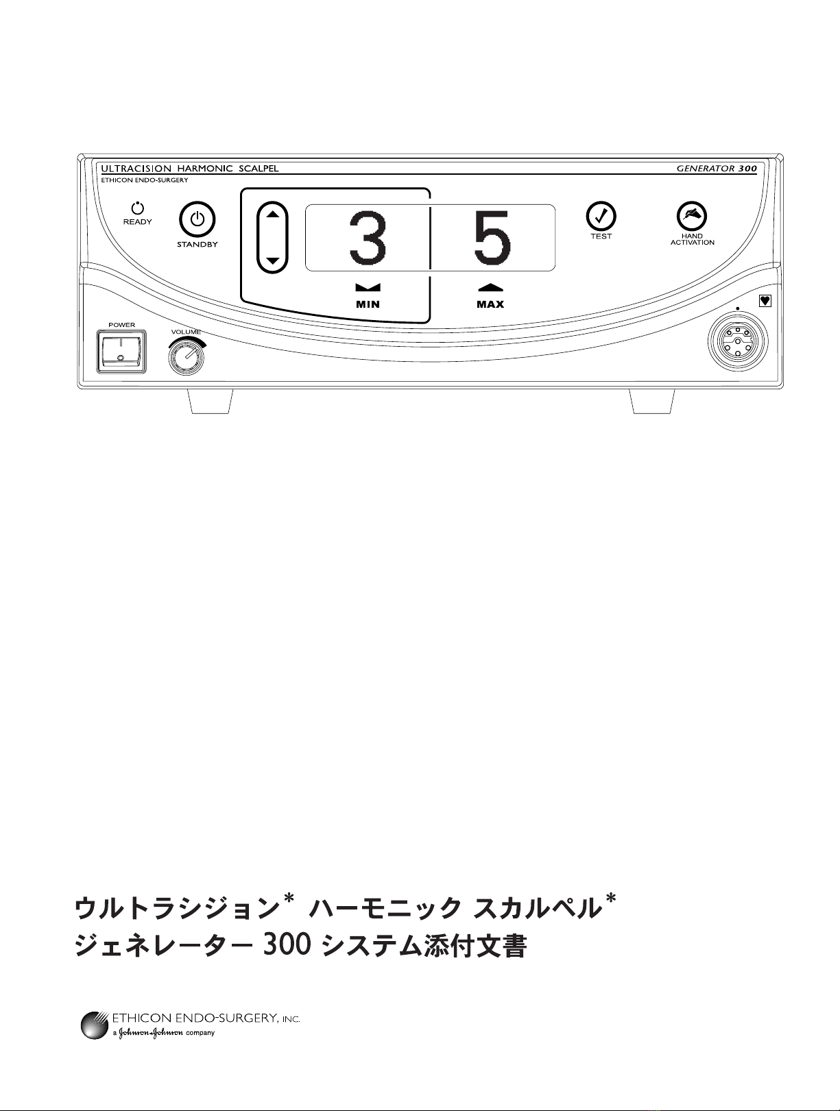
ULT R A CISION®HARMONIC SCALPEL®
Generator 300 System User Manual
Manuel d’utilisation du Système de Générateur 300
Bedienungsanleitung für das Generator 300 System
Manuale dell’operatore del sistema generatore 300
Manual do utilizador do Sistema Gerador 300
Manual del usuario del sistema generador 300
Gebruikershandleiding generator 300-systeem
Brugermanual til generator 300 system
Generaattorijärjestelmän 300 käyttöopas
∂Á¯ÂÈÚ›‰ÈÔ XÚ‹Û˘ ÙÔ˘ ™˘ÛÙ‹Ì·ÙÔ˜ °ÂÓÓ‹ÙÚÈ· 300
Användarhandledning för generator 300-systemet
Instrukcja obs∏ugi systemu generatora 300
Generátor 300 rendszer Használati útmutató
UÏivatelská pfiíruãka systému Generator 300
PouÏívateºská príruãka pre systém Generator 300
Item # 32a

GEN04

GEN04
Table of Contents
Chapter 1 – General Information . . . . . . . . . . . . . . . . . . . . . . . . . . . . . . . . . . . . . . . . . . . . . . . . . . . . . . . . 1
Indications . . . . . . . . . . . . . . . . . . . . . . . . . . . . . . . . . . . . . . . . . . . . . . . . . . . . . . . . . . . . . . . . 1
Contraindications . . . . . . . . . . . . . . . . . . . . . . . . . . . . . . . . . . . . . . . . . . . . . . . . . . . . . . . . . . 1
Chapter 2 – Principles of Operation . . . . . . . . . . . . . . . . . . . . . . . . . . . . . . . . . . . . . . . . . . . . . . . . . . . . . . 3
System Components . . . . . . . . . . . . . . . . . . . . . . . . . . . . . . . . . . . . . . . . . . . . . . . . . . . . . . . . 3
Generator 300 . . . . . . . . . . . . . . . . . . . . . . . . . . . . . . . . . . . . . . . . . . . . . . . . . . . . . . . . 3
Hand Piece . . . . . . . . . . . . . . . . . . . . . . . . . . . . . . . . . . . . . . . . . . . . . . . . . . . . . . . . . . . 3
Instrument . . . . . . . . . . . . . . . . . . . . . . . . . . . . . . . . . . . . . . . . . . . . . . . . . . . . . . . . . . . . 3
Power Levels . . . . . . . . . . . . . . . . . . . . . . . . . . . . . . . . . . . . . . . . . . . . . . . . . . . . . . . . . . . . . . 3
Controls, Indicators, and Connections . . . . . . . . . . . . . . . . . . . . . . . . . . . . . . . . . . . . . . . . . . 4
Unpacking Instructions . . . . . . . . . . . . . . . . . . . . . . . . . . . . . . . . . . . . . . . . . . . . . . . . . . . . . . 6
Chapter 3 – System Setup and Operation . . . . . . . . . . . . . . . . . . . . . . . . . . . . . . . . . . . . . . . . . . . . . . . . 7
System Startup . . . . . . . . . . . . . . . . . . . . . . . . . . . . . . . . . . . . . . . . . . . . . . . . . . . . . . . . . . . . 7
System Operation . . . . . . . . . . . . . . . . . . . . . . . . . . . . . . . . . . . . . . . . . . . . . . . . . . . . . . . . . . 9
System Shutdown . . . . . . . . . . . . . . . . . . . . . . . . . . . . . . . . . . . . . . . . . . . . . . . . . . . . . . . . . 10
Chapter 4 – Troubleshooting . . . . . . . . . . . . . . . . . . . . . . . . . . . . . . . . . . . . . . . . . . . . . . . . . . . . . . . . . . . 11
Audible Indicators and Alarms . . . . . . . . . . . . . . . . . . . . . . . . . . . . . . . . . . . . . . . . . . . . . . . 11
Error Codes . . . . . . . . . . . . . . . . . . . . . . . . . . . . . . . . . . . . . . . . . . . . . . . . . . . . . . . . . . . . . 11
Chapter 5 – Cleaning and Disinfection . . . . . . . . . . . . . . . . . . . . . . . . . . . . . . . . . . . . . . . . . . . . . . . . . . . 17
Generator and Cart Cleaning . . . . . . . . . . . . . . . . . . . . . . . . . . . . . . . . . . . . . . . . . . . . . . . . 17
Foot Switch Cleaning . . . . . . . . . . . . . . . . . . . . . . . . . . . . . . . . . . . . . . . . . . . . . . . . . . . . . . 17
Chapter 6 – Safety and Function Testing . . . . . . . . . . . . . . . . . . . . . . . . . . . . . . . . . . . . . . . . . . . . . . . . . 19
Safety Test . . . . . . . . . . . . . . . . . . . . . . . . . . . . . . . . . . . . . . . . . . . . . . . . . . . . . . . . . . . . . . . 19
Function Test . . . . . . . . . . . . . . . . . . . . . . . . . . . . . . . . . . . . . . . . . . . . . . . . . . . . . . . . . . . . . 19
Calibration . . . . . . . . . . . . . . . . . . . . . . . . . . . . . . . . . . . . . . . . . . . . . . . . . . . . . . . . . . . . . . 19
Chapter 7 – Warnings and Precautions . . . . . . . . . . . . . . . . . . . . . . . . . . . . . . . . . . . . . . . . . . . . . . . . . . 21
System Warnings and Precautions . . . . . . . . . . . . . . . . . . . . . . . . . . . . . . . . . . . . . . . . . . . . . 21
Instrument Warnings and Precautions . . . . . . . . . . . . . . . . . . . . . . . . . . . . . . . . . . . . . . . . . . 22
Chapter 8 – System Specifications . . . . . . . . . . . . . . . . . . . . . . . . . . . . . . . . . . . . . . . . . . . . . . . . . . . . . . 23
Chapter 9 – Warranty . . . . . . . . . . . . . . . . . . . . . . . . . . . . . . . . . . . . . . . . . . . . . . . . . . . . . . . . . . . . . . . . . 25
Chapter 10 – Symbols . . . . . . . . . . . . . . . . . . . . . . . . . . . . . . . . . . . . . . . . . . . . . . . . . . . . . . . . . . . . . . . . . 27

GEN04

Please read all information carefully.
Failure to properly follow the instructions may lead to serious surgical consequences.
Important: The ULTRACISION®HARMONIC SCALPEL®Generator 300 System User Manual is designed to provide instructions for
use of the ULTRACISION HARMONIC SCALPEL Generator 300, Foot Switch, and Cart (see Chapter 8 – System Specifications - for
applicable product codes). This manual is not a reference to surgical techniques.
Note: Refer to package inserts provided separately for information about the Hand Piece, Hand Switching Adaptor, Adaptors,
Test Tip and Instruments prior to using the system.
Indications
The ULTRACISION HARMONIC SCALPEL System is indicated for soft tissue incisions when bleeding control and
minimal thermal injury are desired. The ULTRACISION HARMONIC SCALPEL System instruments can be used as
an adjunct to or substitute for electrosurgery, lasers, and steel scalpels.
Contraindications
•Theinstrumentsarenotindicatedforincisingbone.
•Theinstrumentsarenotintendedforcontraceptivetubalocclusion.
Chapter 1 – General Information
1
GEN04

User Manual
2GEN04

The ULTRACISION HARMONIC SCALPEL System utilizes ultrasonic energy to enable hemostatic cutting and/or
coagulation of soft tissue. The system consists of an ultrasonic generator, a foot switch, an optional hand-
switching adaptor, a hand piece, and a variety of open and minimally invasive instruments.
Important: The ULTRACISION HARMONIC SCALPEL Generator 300 System User Manual is designed to provide
instructions for use of the ULTRACISION HARMONIC SCALPEL Generator 300, Foot Switch, and Cart (see
Chapter 8 – System Specifications for applicable product codes). This manual is not a reference to
surgical techniques.
Note: Refer to package inserts provided separately for information about the Hand Piece, Hand Switching
Adaptor, Adaptors, Test Tip and Instruments prior to using the system.
System Components
Generator 300
The generator supplies the hand piece with electrical energy and facilitates selection of power levels, system
monitoring, and system diagnostics.
Power is delivered by activating the foot switch or hand switch.
Hand Piece
The hand piece contains an acoustic transducer that converts the electrical energy supplied by the generator
to mechanical motion. The transducer is connected to an amplifier which amplifies the motion produced by
the transducer and relays it to the instrument.
Instrument
The mechanical motion from the hand piece advances to the instrument, transmitting ultrasonic energy which
enables hemostatic cutting and/or coagulation of tissue.
Note: Throughout this manual “instrument(s)” refers to ULTRACISION HARMONIC SCALPEL blades, ball
coagulators, or coagulating shears.
Power Levels
The generator delivers two power levels: minimum (MIN) and maximum (MAX). The minimum power
level may be adjusted by the user from Level 1 to 5. The maximum power level is always Level 5. With all
instruments except the ball coagulator, use a higher generator power level for greater tissue cutting speed and
a lower generator power level for greater coagulation. For the ball coagulator, higher generator power levels
will provide greater coagulation. The amount of energy delivered to the tissue and resultant tissue effects are
a function of many factors including the power level selected, instrument characteristics, grip force (when
applicable), tissue tension, tissue type, pathology, and surgical technique.
Note: Refer to the instruments’ package inserts for additional power level information, including
recommended starting power levels.
Chapter 2 – Principles of Operation
3GEN04
User Manual
4GEN04
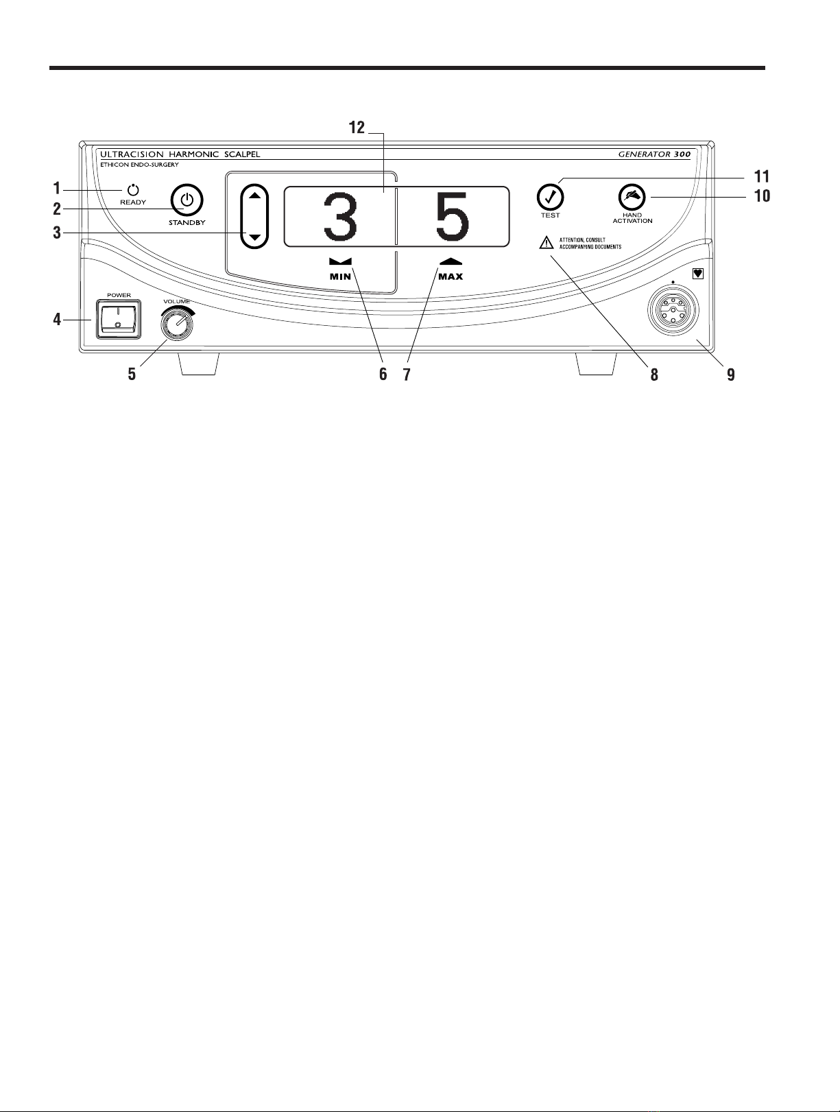
Controls, Indicators, and Connections
Fig. 2-1 Front Panel
1READY When this indicator is green, the system is ready for activation.
2STANDBYPush this button to toggle between Standby and Ready modes. In Standby mode,
this button, and the STANDBY icon, light up and all power is removed from the
hand piece. Both the foot switch and hand switch are disabled. Upon power-up, the
system defaults to Standby mode enabled.
3INCREASE/Push this button to increase or decrease the minimum (MIN) power
DECREASE POWER setting to the desired level (from 1 to 5). The level chosen will be shown on the
LEVEL graphic display. The power level may be adjusted when the generator is in Ready or
Standby mode.
4POWER This switch controls the main electrical power to the generator.
5VOLUMETurn this knob to adjust the volume of the activation tones. A tone will sound
indicating the volume level selected.
6MIN Indicates the user-settable minimum power level setting. When this power level is
activated (by foot switch or hand switch), the “MIN” indicator will flash. The
system defaults to “MIN” power level 3. Refer to the instruments’ package inserts
for the recommended minimum power level.
7MAX Indicates the maximum power level setting. This setting is always “5”. When this
power level is activated (by foot switch or hand switch), the “MAX” indicator
will flash.
8ALARMINDICATORThis red indicator appears only if a system alarm occurs in response to a component
or generator problem.
9HANDPIECEThis receptacle is used to connect the hand piece to the generator.
RECEPTACLE
10 HAND ACTIVATION When the indicator is green, hand activation on the hand switching adaptor is
enabled. To disable the Hand Activation mode, depress the button. Upon power-up,
the system defaults to Hand Activation mode disabled.
Note: If the foot switch is installed, the foot switch is always enabled.
11 TEST Depressing this button initiates the Test mode. This mode is used during
troubleshooting. The generator will emit a tone when the Test mode is active and
“TEST IN PROGRESS” will appear on the display.
12 GRAPHIC DISPLAY In Ready or Standby modes, this display indicates the minimum (user-settable
level 1 to 5) and maximum (level 5) power levels. If a system or component
problem exists, error codes will appear on this display.
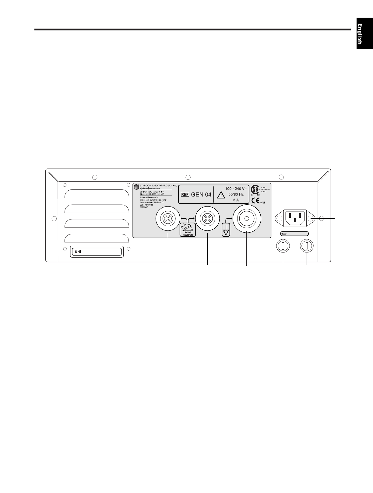
Fig. 2-2 Back Panel
13 FOOT SWITCH Identical receptacles allow connection of up to two foot switches for
RECEPTACLES user convenience. If only one foot switch is used, connect to either receptacle.
14 POTENTIAL This terminal provides a means for connection to a Potential Equalization
EQUALIZATION Conductor.
TERMINAL
15 FUSES See the ULTRACISION HARMONIC SCALPEL Generator 300 Service Manual for
additional information.
16 POWER CORD This receptacle is used to attach the power cord to the generator. For power cord
RECEPTACLE requirements, see Chapter 8 – System Specifications.
AUDIBLE SIGNALS The generator delivers audible tones to signal activation and alarm states. The user
may choose from three activation tone pitches. See Chapter 3 – System Setup and
Operation for tone selection information. Upon power-up, the system defaults to the
last tone chosen (the mid-pitch tone is factory-set).
Chapter 2 – Principles of Operation
5GEN04
-
T3.15H 250V
13 14 15
16

GEN04
User Manual
6
Unpacking Instructions
The ULTRACISION HARMONIC SCALPEL Generator 300 System includes several components that are purchased
separately. Upon receiving the ordered components, check for visible shipping damage. If damage is seen,
contact your Ethicon Endo-Surgery representative.
System components may include the following parts (for product codes, see Chapter 8 – System
Specifications):
Generator 300 – includes the generator, power cord, user manual, and service manual.
Note: The User Manual includes a troubleshooting guide (see back pocket of manual binder). Remove the
self-adhesive guide’s backing and adhere the guide to the top panel of the generator. Placement guides for the
Troubleshooting Guide are found on the generator’s top panel.
Foot Switch – includes the foot switch and detachable cable assembly.
Note: The foot switch is required if the system will be used with coagulating shears or instruments without
the hand switching adaptor. Since the generator has receptacles for two foot switches, two foot switches may
have been shipped.
Cart – the cart is optional. It is designed to hold one ULT R ACISION HARMONIC SCALPEL Generator. The cart
requires assembly; instructions are included with the cart.

System Startup
Warning: Products manufactured or distributed by companies other than Ethicon Endo-Surgery, Inc. may not
be compatible with the ULTRACISION HARMONIC SCALPEL System. Use of such products may lead to
unanticipated results and possible injury to the user or patient.
Caution: The ULTRACISION HARMONIC SCALPEL system includes components that are shipped non-sterile
(e.g. hand piece, hand switching adaptor, adaptors, and blade wrench). Sterilize products as required before
beginning system setup. Refer to individual package inserts for cleaning and sterilization instructions.
1Confirm that the generator power switch is off during setup.
2Secure the generator on its cart or on another suitable fixture. To secure the generator on its
cart, place the generator’s rubber feet into the corresponding holes on the cart. Push down on
the generator’s top panel.
Caution: To prevent overheating during use, ensure that the air vents found on the
generator’s bottom and back panels are not blocked and that they allow adequate clearance
from obstructions to allow air to flow freely through the generator enclosure. Avoid placing
the generator on a soft surface.
Warning: The ULTR ACISION HARMONIC SCALPEL system must be operated within the
required ambient operating conditions. Refer to Chapter 8 – System Specifications for
requirements.
Caution: Do not simultaneously touch the patient and generator.
3Connect the line cord into the AC inlet located on the generator’s rear panel and into an
appropriately-grounded outlet. If the power cord is wrapped around the cart handle, it must
be completely removed from the cart handle prior to plugging it into the power outlet.
Warning: Verify that the outlet voltage correctly corresponds to the generator’s requirements
(see Chapter 8 – System Specifications). Connection to an improper power supply may
result in damage to the generator and risk of shock or fire hazard.
4a. Attach the foot switch cable to the foot switch:
Note: Although installation of the foot switch is optional when using the hand switching
adaptor, installing the foot switch is recommended in case its use is needed during the
procedure.
• Confirm that the connector and receptacle are dry and clean.
•Orienttheslotonthefootswitchcable’slargerconnectorat12o’clock.
•Seattheconnectorinthefootswitchreceptacle.
•Turntheconnectorcollarclockwiseuntiltight.Ensurethecollarisfinger-tightto
prevent inadvertent activation because of fluid ingress.
b. Connect the foot switch cable’s smaller connector to the foot switch receptacle on the rear
panel of the generator.
• Confirm that the connector and receptacle are dry and clean.
•Alignthereddotonthefootswitch4-pinconnectorwiththereddotonthe4-pin
receptacle on the generator back panel.
Note: The generator has two identical foot switch receptacles. If one foot switch is used,
either receptacle may be used.
Repeat steps 4a and 4b if a second foot switch will be used.
Chapter 3 – System Setup and Operation
7GEN04

5Connect the instrument and adaptor (or hand switching adaptor), if required, to the hand
piece following instructions in their package inserts.
Note: The hand switching adaptor must be at room temperature to function properly. Do not
immerse in water to cool rapidly. After steam sterilization, allow hand switching adaptor to
air cool for at least 15 minutes prior to use.
6Connect the hand piece connector to the receptacle on the front panel. Align the white dot on
the connector with the white dot on the generator. Ensure the hand piece connector is clean
and dry before connecting the hand piece to the generator. Fully insert the hand piece
connector to assure complete, proper connection to the generator.
7Turn the generator power switch on and observe the power-up sequence. During power-up,
the following indicators on the front panel will briefly illuminate:
• READY, STANDBY, MIN, MAX, TEST, ATTENTION, HAND ACTIVATION
The system will run its start-up sequence and display the software version. An audible tone
will sound during the initiation sequence.
Note: The entire power-up initiation sequence should not exceed ten seconds.
If the start-up sequence deviates from the description above, contact qualified service personnel
following hospital protocol.
When the initiation sequence is complete, the system will go to Standby. However, if the system
detects a faulty generator or incorrect hand piece, a fault will appear on the graphic display (the
power levels will not be visible) and an audible alarm will sound. Refer to Chapter 4 –
Troubleshooting or the Troubleshooting Guide.
8Power Levels: Upon startup, the generator defaults to power level 3 (MIN) and 5 (MAX).
The minimum (MIN) power level is user-settable from power levels 1 to 5. To adjust the
power level, depress the up/down arrow button to the left of the minimum power level
display. Set the power level based on surgeon preference and/or recommendations provided
in the instrument’s package insert (for more information, see Power Levels section in
Chapter 2 – Principles of Operation).
9Audible tones: The generator has three activation tone sets from which to choose (the mid-
pitch tone is factory set). To choose another tone:
a. Switch power off.
b. Switch power on. Then immediately depress and hold both the STANDBY and HAND
ACTIVATION buttons. When the graphic shown in Figure 3-1 appears on the display,
release the STANDBY and HAND ACTIVATION buttons.
c. While in the Tone Selection mode, the generator will automatically sequence through the
available tone pitches. To select a tone, depress any button on the control panel. The
generator will return to Standby mode. The tone chosen will be saved until it is changed
again by accessing the Tone Selection mode.
Fig. 3-1 Tone Selection Display
Adjust tone volume by turning the knob on the lower left corner of the control panel. A
tone will sound to indicate the volume level selected. For safety reasons, the tone may not
be disabled.
User Manual
8GEN04

System Operation
Important: The ULTRACISION HARMONIC SCALPEL Generator 300 System User Manual is designed to
provide instructions for use of the ULTR ACISION HARMONIC SCALPEL Generator 300, Foot Switch, and
Cart (see Chapter 8 – System Specifications - for applicable product codes). This manual is not a
reference to surgical techniques.
Note: Refer to package inserts provided separately for information about the Hand Piece, Hand
Switching Adaptor, Adaptors, Test Tip and Instruments prior to using the system.
After completing system setup, the system may be operated.
1Place the generator in Ready mode by depressing the STANDBY button.
2System check and activation:
Each time the generator is activated after exiting Standby, hold the instrument in the air (if
coagulating shears are used, open the clamp arm) and depress the MIN or MAX power level
on the foot switch or hand switching adaptor. “TEST IN PROGRESS” will appear on the
graphic display and a rapid two-tone pulse will sound while the test is occurring. During this
five-second period, a system check is being performed.
•Ifthesystemisoperatingproperly,theactivationtonecorrespondingtothepower
level activated will be heard when the check is complete. Stop activation, position
the instrument on tissue, and resume activation.
•Ifthesystemisnotoperatingproperly,anerrorcodewillappear(refertoChapter4
– Troubleshooting or the Troubleshooting Guide).
Warning: To avoid user or patient injury, ensure that the instrument is clear of other
instruments, drapes, the patient or other objects during the system check. Safety measures
(in accordance with hospital protocol) taken in the presence of aerosols should be in effect
during the system check.
Note: The foot switch or hand switch must be depressed until the system check is completed.
If the switch is released prematurely, the check will reinitiate at the next activation.
Note: The system check will also be performed whenever the hand piece is removed and
replaced or TEST is pressed.
Note: The hand activation button on the generator control panel must be illuminated for the
hand switches to be active. To deactivate the hand switches, depress the hand activation
button (if the hand activation button is not illuminated, hand switches will be inactive).
Note: If the hand switch will not turn off during operation, depress the button corresponding
to the power level opposite that being activated to turn it off - an alarm will sound. Press the
HAND ACTIVATION button to disable the hand switching adaptor. Place the generator in
Standby, and replace the hand switch; or, continue using the foot switch after deactivating
the hand switch.
If the foot switch will not turn off during operation, depress the pedal corresponding to the
power level opposite that being activated to turn it off - an alarm will sound. Release the
pedal to silence the alarm. Place the generator in Standby, and replace the foot switch.
Chapter 3 – System Setup and Operation
9GEN04

3If the system senses a generator, hand piece, or instrument fault during use, an audible alarm
(tone with long pulses) will sound and a visual alarm indicator will appear on the control
panel. (Refer to Chapter 4 – Troubleshooting or the Troubleshooting Guide to resolve the
problem.)
Warning: Place the generator in Standby mode before removing or replacing an instrument,
hand switching adaptor or hand piece or when the system is not in use.
System Shutdown
1Turn the generator power switch off and remove power cord from outlet.
2Disconnect the hand piece, instrument, and adaptor or hand switching adaptor (if used) and
process them as indicated in their respective package inserts.
3Clean the generator and cart and disinfect the foot switch(es) following hospital protocol (for
recommendations, refer to Chapter 5 – Cleaning and Disinfection).
4Store foot switch(es) on the cart shelves provided. Each shelf will hold one foot switch.
5Wrap foot switch cable(s) and the power cord on the cart’s back handle for storage.
User Manual
10 GEN04

The Generator 300 System supports a series of alarms and error codes to help in the identification and
troubleshooting of component problems. These guides are meant as an adjunct to, but not a substitute for,
clinical judgment and observations.
Audible Indicators and Alarms
Tone Possible Cause and Corrective Action
No tone when system is activated. Confirm foot switch is fully connected (if hand switch is not
being used).
Confirm foot switch is not faulty.
If hand switch is used, confirm it is connected and not faulty.
Confirm hand activation is enabled if hand switching adaptor is
being used.
Activation (brief pulses) System is being activated or is in Test mode. System is operating
properly. MIN and MAX power have unique tones.
Alert (three-tone sequence) Activation is attempted while generator is in Standby mode. Push the
STANDBY button to return the generator to Ready mode.
Two or more foot or hand switches are recognized by the generator as
being activated simultaneously. Reactivate using only one switch.
Constant tone 1) Instrument is in contact with too much tissue. Reduce the amount of
tissue in contact with the instrument. If tone persists, carefully remove
any tissue that has collected in the distal end of the instrument shaft.
2) Hand piece and/or blade fault. Press TEST to identify source of fault.
Prolonged solid tone during Hand piece and/or blade fault. Press TEST to identify source of fault.
activation (exceeds 10 seconds)
Alarm (two-tone sequence) A component or system problem has occurred. Refer to the Error
Codes section in this chapter or the Troubleshooting Guide.
Note: This alarm will activate for three seconds, then will silence itself
for 30 seconds. This cycle will continue until the error is resolved or
the main power switch is turned off.
Error Codes
The generator will recognize specific faults in five areas: generator, hand piece, instrument, foot switch or
hand switch. When a fault is identified, an alarm will sound, the alarm indicator will appear on the generator
control panel, and the source of the problem will appear on the graphic display (the power levels will not be
displayed). See Fig. 4-1 below for an example. Follow the procedures outlined below (or in the
Troubleshooting Guide) to resolve the problem.
Fig. 4-1 Alarm Indicator (example)
Chapter 4 – Troubleshooting
11GEN04

GEN04
User Manual
12
Error Code 1: Generator Error Code 1 indicates either there is a functional problem with the
generator or the front panel button(s) were activated during power-up
sequence.
Cycle the power OFF then ON. If error persists, power off system and
contact service.
Error Code 2: Generator Error Code 2 indicates that the generator is overheating.
Temperature
1Power off system. Remove any obstructions blocking the air
vents on the generator’s bottom and back panels. If there is no
apparent obstruction or external heat source, contact service.
2Power on the system and wait for up to 30 minutes for generator
error to clear.
3If error code persists, contact service.
Error Code 3: Hand Piece Error Code 3 indicates a problem with the hand piece.
1Confirm that the hand piece connector is fully inserted and
properly oriented – white dot on handpiece is aligned with white
dot on front panel. If the error code does not clear within three
seconds after the hand piece is properly connected, press TEST.
2The instrument may not be tightened properly or tissue may
have collected in the distal end of the instrument shaft. Tighten
instrument using blade wrench and carefully remove tissue from
distal end of instrument sheath. Press STANDBY to clear error
code and return to Ready mode. Activate system. If the pre-run
test is running, ensure instrument is in air. If using shears, ensure
jaws are open and not in contact with any objects during pre-
run test.
Note: Inspect the blade wrench hub for cracks or wear before use. If
damage is seen, replace the blade wrench. Before use after
autoclaving, cool the blade wrench at room temperature for at least 45
minutes or soak it in room temperature sterile water for 5 minutes.
3If the error persists, install a test tip to isolate the problem. Press
TEST button.
-Ifsystemindicatesahandpieceerror,handpieceisbador
test tip is bad. Replace hand piece or install a new test tip
and press TEST.
-Ifnoerroroccurswithtesttipattached,replaceinstrument.
4Press STANDBY to return to Ready mode. Activate system.
Error Code 4: Hand Piece Error Code 4 indicates that the hand piece has exceeded its
Temperature specified operating temperature. For immediate recovery, use another
hand piece; or, follow the steps below to determine the cause of the
error condition and alternate recovery methods.

The following are possible causes of an increase in hand piece
temperature. To correct, complete the appropriate steps below and
allow the hand piece to cool before resuming operation.
1The hand piece is still warm from recent steam sterilization.
Allow the hand piece to cool at room temperature for at least 45
minutes or soak it in room-temperature sterile water for 5
minutes before resuming operation.
Note: The hand switching adaptor (HSA07) should not be submerged
for rapid cooling purposes. This may render the hand switching
adaptor inoperable for an extended period of time. After steam
sterilization, allow the hand switching adaptor to air cool at least
15 minutes prior to use.
2The instrument may not be tightened properly or tissue may
have collected in the distal end of the instrument shaft. Tighten
instrument using blade wrench and carefully remove tissue from
distal end of instrument sheath. Press STANDBY to clear error
code and return to Ready mode. Activate system. If the pre-run
test is running, ensure instrument is in air. If using shears, ensure
jaws are open and not in contact with any objects during pre-
run test.
Note: Inspect the blade wrench hub for cracks or wear before use. If
damage is seen, replace the blade wrench. Before use after
autoclaving, cool the blade wrench at room temperature for at least 45
minutes or soak it in room temperature sterile water for 5 minutes.
3If the error persists, install a test tip to isolate the problem. Press
TEST button.
-Ifsystemindicatesahandpieceerror,handpieceisbador
test tip is bad. Replace hand piece or install a new test tip
and press TEST.
-Ifnoerroroccurswithtesttipattached,replaceinstrument.
4Press STANDBY to return to Ready mode. Activate system.
5If the hand piece does not show evidence of overheating and
troubleshooting steps 1-4 above do not appear to resolve the
problem, perform the following:
a. Leave the hand piece at room temperature for 24 hours or
more.
b. Remove any test tip or instrument from the hand piece.
c. With the generator turned off, plug the hand piece into any
Generator 300.
d. Power up the generator in Biomed mode.
-PressandholddowntheSTANDBYbuttonanddown
arrow key.
-Waitforasteadydisplay–approximately10seconds.
-Ifa“Generator”erroroccurs,thenoneofthebuttonswas
not properly held down. If this happens, repeat the power up
procedure in Biomed mode.
Chapter 4 – Troubleshooting
13GEN04

e. Record the “XDUCER CAPACITANCE” value.
-PresstheSTANDBYbutton,ifnecessary,until
it illuminates.
-Usetheincrease/decreasearrowkeystogetto
“Page 2 of 21”.
-Recordthenumberopposite“XDUCERCAPACITANCE”.
-PresstheSTANDBYbuttonuntiltheStandbylight
turns off.
-Leavethehandpiecepluggedintothegenerator.Donot
remove hand piece during entire procedure. Do not activate
the MIN or MAX activation buttons on the foot switch or
hand switch if either is attached.
-Afteraperiodoftimethatexceeds30ormoreminutes,
press the STANDBY button until the STANDBY light
is illuminated.
-Again,readthe“XDUCERCAPACITANCE”on
Page 2 of 21.
-Ifthenumberhaschanged,theupdatewassuccessful.
-Ifthenumberhasnotchanged,thenthisupdateattemptdid
not succeed. Power down the generator and repeat Step 5.
Note: As the hand piece ages, the generator performs measurements
and updates a key hand piece parameter. This function is performed
when the internal temperature of the hand piece is stable at room
temperature. Certain usage patterns may prevent this update from
occurring and subsequently make the hand piece diagnostics more
sensitive to temperature. The steps above will cause an update of the
hand piece parameter and return the system to designed sensitivity.
Warning: To avoid user or patient injury, ensure that the instrument is
clear of other instruments, drapes, the patient or other objects before
pressing TEST. Safety measures (in accordance with hospital protocol)
taken in the presence of aerosols should be in effect while in Test mode.
Note: Do not run the Test mode while an electrosurgical generator is
being activated in the room. Interference from the electrosurgical
generator may affect test results.
Error Code 5: Instrument Error Code 5 indicates a problem with the instrument.
1The instrument may not be tightened properly or tissue may
have collected in the distal end of the instrument shaft. Tighten
instrument using blade wrench and carefully remove tissue from
distal end of instrument sheath. Press STANDBY to clear error
code and return to Ready mode. Activate system. If the pre-run
test is running, ensure instrument is in air. If using shears,
ensure jaws are open and not in contact with any objects
during pre-run test.
User Manual
14 GEN04

Note: Inspect the blade wrench hub for cracks or wear before use.
If damage is seen, replace the blade wrench. Before use after
autoclaving, cool the blade wrench at room temperature for at least
45 minutes or soak it in room temperature sterile water for 5 minutes.
2If the error persists, install a test tip to isolate the problem. Press
TEST button.
-Ifsystemindicatesahandpieceerror,handpieceisbador
test tip is bad. Replace hand piece or install a new test tip
and press TEST.
-Ifnoerroroccurswithtesttipattached,replaceinstrument.
3Press STANDBY to return to Ready mode. Activate system.
Note: Inspect the blade wrench hub for cracks or wear before use.
If damage is seen, replace the blade wrench. Before use after
autoclaving, cool the blade wrench at room temperature for at least
45 minutes or soak it in room temperature sterile water for 5 minutes.
Warning: To avoid user or patient injury, ensure that the instrument
is clear of other instruments, drapes, the patient, or other interference
before pressing TEST. Safety measures (in accordance with hospital
protocol) taken in the presence of aerosols should be in effect while
in Test mode.
Note: Do not run the Test mode while an electrosurgical generator is
being activated in the room. Interference from the electrosurgical
generator may affect test results.
Error Code 6: Foot Switch Error Code 6 indicates a foot switch pedal is stuck in the ON position.
Confirm generator receptacle, foot switch receptacles and cable
connectors are clean and dry or replace the foot switch.
Note: If the error persists, replace foot switch.
Error Code 7: Hand Switch Error Code 7 indicates the hand switch is stuck in the ON position.
Confirm contacts in the distal end of hand piece and in the proximal
end of the hand switching adaptor are dry or replace the hand
switching adaptor.
Note: If the error persists, replace hand switch.
Chapter 4 – Troubleshooting
15GEN04

User Manual
16 GEN04
Table of contents
Other Ethicon Endo-Surgery Medical Equipment manuals


Popular Medical Equipment manuals by other brands


Getinge
Getinge Arjohuntleigh Nimbus 3 Professional Instructions for use

Mettler Electronics
Mettler Electronics Sonicator 730 Maintenance manual

Pressalit Care
Pressalit Care R1100 Mounting instruction

Denas MS
Denas MS DENAS-T operating manual

bort medical
bort medical ActiveColor quick guide

AccuVein
AccuVein AV400 user manual


