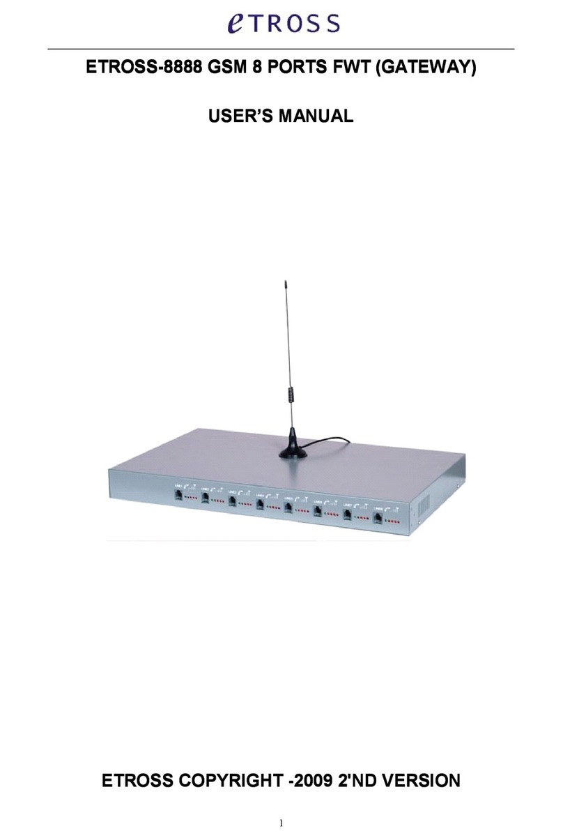
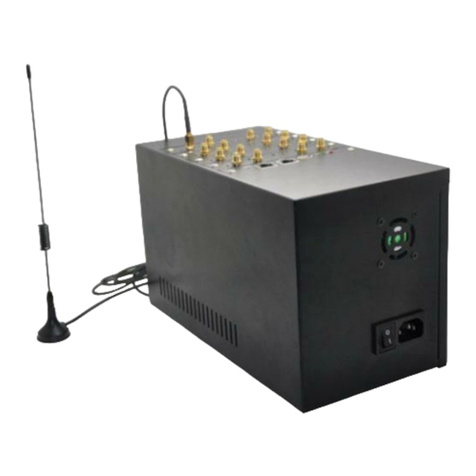
Etross ETROSS-8888 User manual

1
ETROSS-8888
ETROSS-8888
ETROSS-8888
ETROSS-8888
GSM
GSM
GSM
GSM
8
8
8
8
PORTS
PORTS
PORTS
PORTS
FWT
FWT
FWT
FWT
(GATEWAY)
(GATEWAY)
(GATEWAY)
(GATEWAY)
USER
USER
USER
USER
’
’
’
’
S
S
S
S
MANUAL
MANUAL
MANUAL
MANUAL
ETROSS
ETROSS
ETROSS
ETROSS
COPYRIGHT
COPYRIGHT
COPYRIGHT
COPYRIGHT
-2009
-2009
-2009
-2009
2'ND
2'ND
2'ND
2'ND
VERSION
VERSION
VERSION
VERSION
All manuals and user guides at all-guides.com
all-guides.com

2
1,General
1,General
1,General
1,General
Description:
Description:
Description:
Description:
Etross-8888 is a GSM to Analog Converter , the device can produce a FXS line to allow a
regular phone to be connected and used just like a local landline (PSTN) except your calls will
go out the GSM network. This device can both receive and make calls .
The main application is: Connecting the RJ-11 FXS line to connect Ordinary telephone set for
voice call, to connect PBX for call extentions, to connect billing systems for public phone use, to
connect VoIP gateway to realize VoIP call termination, to conn ect alarm system for security
purpose, etc. It is not a VOIP gateway , nor a GSM+VOIP gateway, It is a GSM Fixed Wireless
Terminal that p roduces a Analog FXS phone line .
Available
Available
Available
Available
in
in
in
in
GSM
GSM
GSM
GSM
900/1800Mhz
900/1800Mhz
900/1800Mhz
900/1800Mhz
dual
dual
dual
dual
band,
band,
band,
band,
GSM
GSM
GSM
GSM
900/1800/1900Mhz
900/1800/1900Mhz
900/1800/1900Mhz
900/1800/1900Mhz
Tri-band,
Tri-band,
Tri-band,
Tri-band,
GSM850/900/1800/1900Mhz
Quadband.
Quadband.
Quadband.
Quadband.
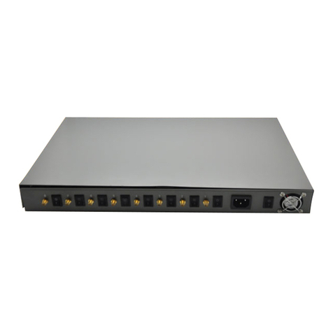
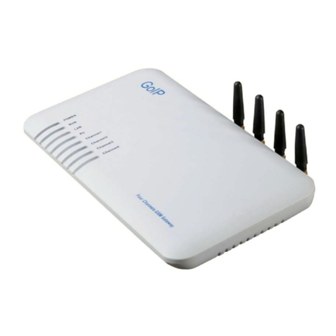
1, Front Picture 2, Rear Picture
3, Front Picture with Antenna connection 4, Bottom side picture
1) , Front
Front
Front
Front
side
side
side
side
has 8pcs RJ-11 ports, and LEDs display for Signal strength , Power, Working
Status and Talking indicator;
2) , Rear
Rear
Rear
Rear
side
side
side
side
has 8pcs SMA antenna connectors, Power switch for every terminal, General
Power port and switch;
3) , Front
Front
Front
Front
side
side
side
side
with
with
with
with
8pcs
8pcs
8pcs
8pcs
antennas
antennas
antennas
antennas
, this only for display picture, in installation, antenna must
be put beyond 1.5 from terminal. Can ’ t be put on the terminal, otherwise it will make noise;
All manuals and user guides at all-guides.com

3
4) , Bottom
Bottom
Bottom
Bottom
side
side
side
side
has 8pcs Sim card holder slots, you can insert Sim card for each slot when
installation.
2,Fe
2,Fe
2,Fe
2,Fe
atures:
atures:
atures:
atures:
1) It is a 8 channels GSM Gateway that has 8 ports FXS interfaces ;
2) It can connect with ordinary tele phone set, PBX , VOIP Gateway, Billing meter etc. ;
3) Dialing tone frequency:450hz ;
4) Employ Industrial module S im300 (900/1800/1900Mhz) , M10(850/900/1800/1900Mhz),
Wavecom Q2403A( 900/1800MHZ) to make ;
5) Can adjust dial interval from 0.5sec to 9 secs by setting up from telephone set;
6) Can adjust voice volume by setting up from telephone set;
7) SIM card supported (1.8V, 3V)
;
8) Caller ID display ;
9) DTMF Dialing ;
10) Bell signal ;
11) Polarity reversal ;
12) The RJ-11 socket which connect the phone or billing system for metering purpose ;
13) Antenna socket (SMA) ;
14) IP Presetting ;
15) Working status and Signal Strength by LED indicator;
16) IMEI Change (optional)
3,
3,
3,
3,
Technical
Technical
Technical
Technical
Specifications
Specifications
Specifications
Specifications
Air interface standard: GSM850/1900Mhz,900/1,800Mhz phase 2+ full band
Frequency ranges:
A)
A)
A)
A)
GSM
GSM
GSM
GSM
850
850
850
850
GSM
GSM
GSM
GSM
1900:
1900:
1900:
1900:
I) Transmission: 869.2 ~ 893.8MHz I) Transmission: 1, 930 ~ 1, 990MHz
Ii) Reception: 824.2 ~ 848.2MHz Ii) Reception: 1, 850 ~ 1, 910MHz
B)
B)
B)
B)
GSM
GSM
GSM
GSM
900:
900:
900:
900:
GSM
GSM
GSM
GSM
1800:
1800:
1800:
1800:
I) Transmission: 890 ~ 915MHz I) Transmission: 1, 710 ~ 1, 785MHz
Ii) Reception: 935 ~ 960MHz Ii) Reception: 1, 805 ~ 1, 880MHz
Phone interface: supply RJ-11 Phone Interface
Hanging voltage: 45V
Picking off voltage: 30mA
/
41mA
Dialing tone Frequency: 450Hz
Antenna interface: Antenna amplifying> 2 .5db
Sensitivity:<-104DBM
Transmitting power<3W
AC- Adapter interface: INPUT: AC 110 ~2 4 0V
OUTPUT: 5V 7A
AC-Power type: EU,US,AU,British can be optional
All manuals and user guides at all-guides.com

4
4,
4,
4,
4,
Operation
Operation
Operation
Operation
Circumstance:
Circumstance:
Circumstance:
Circumstance:
Operation temperature: -10c~60C
Storage temperature:-20C~70C
Operation humidity:45%-95%
Atmosphere pressure:86-106Kpa
Environment noise: <60DB
Transmitting Power:2W
Sensitivity: <-104dbm
Antenna Amplifying: >1.5db
Dialing frequency: 450Hz
Hanging voltage: 45V
Picking current: 30mA/41mA
5,Checking
5,Checking
5,Checking
5,Checking
Package:
Package:
Package:
Package:
ETROSS-8888 GSM 8 PORTS FWT: 1pcs
1pcs
1pcs
1pcs
;
Power Supply Cable: 1pcs
1pcs
1pcs
1pcs
,
GSM Antenna with 3m cable: 8pcs
8pcs
8pcs
8pcs
,
User ’ s Manual 1pcs
1pcs
1pcs
1pcs
.
Product dimension: L455x
L455x
L455x
L455x
W280
W280
W280
W280
x
x
x
x
H45mm
H45mm
H45mm
H45mm
Gift box dimension: L510x
L510x
L510x
L510x
W170x
W170x
W170x
W170x
H64mm
H64mm
H64mm
H64mm
G.W: 4.5kg
4.5kg
4.5kg
4.5kg
6,Installation
6,Installation
6,Installation
6,Installation
And
And
And
And
Connection
Connection
Connection
Connection
The
The
The
The
Condition
Condition
Condition
Condition
for
for
for
for
Installation
Installation
Installation
Installation
The terminal asks for 110- 220V
AV
power supply. It must be installed in the area where the
GSM network can cover. The strength of the signal can affect the quality of voice.
1. Screw off the screws that are on the back of the terminal, Insert SIM card for every Sim
card holder, and then tighten the screws.
2. Install antenna. In order to ensure the quality of voice, antenna must be put beyond 1.5
from the telephone and terminal.
3. On end of the telephone line connects to the “ Phone ” port of the terminal, the other end
connects to telephone.
4. “ Power ” port connects to power adapter that is connected to 110-220V AC power supply.
1)
1)
1)
1)
The
The
The
The
Installation
Installation
Installation
Installation
for
for
for
for
Connecting
Connecting
Connecting
Connecting
to
to
to
to
Ordinary
Ordinary
Ordinary
Ordinary
Telephone
Telephone
Telephone
Telephone
The Sketch for connecting ordinary Telephone
All manuals and user guides at all-guides.com

5
Draw
Draw
Draw
Draw
your
your
your
your
attention:
attention:
attention:
attention:
Because there are many types of ordinary telephone and their electric
parameters are different. In order to avoid mutual disturbance between telephone and terminal
and affect voice quality. The distance between telephone and terminal is 1.5m at least.
2)
2)
2)
2)
The
The
The
The
installation
installation
installation
installation
for
for
for
for
connecting
connecting
connecting
connecting
to
to
to
to
billing
billing
billing
billing
device
device
device
device
for
for
for
for
metering
metering
metering
metering
If the users demand to register cost during calls, billing device can be connected between
terminal and ordinary telephone. Billing device register cost according to the anti-polarity signal
that is provided by terminal.
The sketch for connecting to Billing device or Computer charging system
3)
3)
3)
3)
The
The
The
The
installation
installation
installation
installation
for
for
for
for
connecting
connecting
connecting
connecting
to
to
to
to
PBX
PBX
PBX
PBX
for
for
for
for
call
call
call
call
extentions
extentions
extentions
extentions
If users want to connect small PBX to this terminal, connect terminal ’ s “ Phone port ” to the PBX.
The sketch for connecting to PBX device.
All manuals and user guides at all-guides.com

6
4)
4)
4)
4)
The
The
The
The
installation
installation
installation
installation
for
for
for
for
connecting
connecting
connecting
connecting
VoIP
VoIP
VoIP
VoIP
gateway
gateway
gateway
gateway
for
for
for
for
Call
Call
Call
Call
Termination
Termination
Termination
Termination
Suppose a VoIP call originates from US, which was transferred from US Server to China Server
on
VoIP,
finally the call will be terminated from internet to GSM network and to be sent out to
the destination answer side.
The sketch for connecting to VoIP gateway
5)
5)
5)
5)
The
The
The
The
installation
installation
installation
installation
for
for
for
for
connecting
connecting
connecting
connecting
to
to
to
to
alarm
alarm
alarm
alarm
system
system
system
system
for
for
for
for
Security
Security
Security
Security
The GSM FWT can substitute the PSTN for connecting to alarm system for security purpose
when PSTN failure or not available.
The sketch for connecting to alarm system
All manuals and user guides at all-guides.com
all-guides.com

7
7,
7,
7,
7,
Function
Function
Function
Function
Setting
Setting
Setting
Setting
Before you do the following function settings, Lift handset or press hands-free key of telephone
set, then you can press the buttons according to the following instructions to finish setting, you
will hear 2 beeps after you finish, this testify setting su ccessfully.
1)
1)
1)
1)
Adjust
Adjust
Adjust
Adjust
dial
dial
dial
dial
interval
interval
interval
interval
*#01# 3 0# , 01-- command
,
3 0-- time
,
Max 9.9 seconds
,
Min 0.5 seconds, factory default setting i s
3
seconds.
*If
*If
*If
*If
you
you
you
you
use
use
use
use
etross-8888
etross-8888
etross-8888
etross-8888
for
for
for
for
connecting
connecting
connecting
connecting
to
to
to
to
VoIP
VoIP
VoIP
VoIP
gateway,you
gateway,you
gateway,you
gateway,you
can
can
can
can
set
set
set
set
dial
dial
dial
dial
interval
interval
interval
interval
as
as
as
as
0.5
0.5
0.5
0.5
second,
second,
second,
second,
it
it
it
it
can
can
can
can
make
make
make
make
PDD<5
PDD<5
PDD<5
PDD<5
sec
sec
sec
sec
(
(
(
(
Method: *#01#05#);
*If
*If
*If
*If
you
you
you
you
use
use
use
use
etross-8888
etross-8888
etross-8888
etross-8888
for
for
for
for
connecting
connecting
connecting
connecting
telephone,
telephone,
telephone,
telephone,
PBX,
PBX,
PBX,
PBX,
billing
billing
billing
billing
device,
device,
device,
device,
you
you
you
you
can
can
can
can
set
set
set
set
dial
dial
dial
dial
interval
interval
interval
interval
as
as
as
as
3
3
3
3
seconds
seconds
seconds
seconds
or
or
or
or
5
5
5
5
seconds
seconds
seconds
seconds
as
as
as
as
you
you
you
you
like
like
like
like
(Method:
(Method:
(Method:
(Method:
*#01#30#,
*#01#30#,
*#01#30#,
*#01#30#,
set
set
set
set
the
the
the
the
dial
dial
dial
dial
interval
interval
interval
interval
as
as
as
as
3
3
3
3
seconds).
seconds).
seconds).
seconds).
2)
2)
2)
2)
Adjust
Adjust
Adjust
Adjust
Earphone
Earphone
Earphone
Earphone
Volume
Volume
Volume
Volume
*#02#15# 02-- command ,15-- volume ,Max 16 ,Min 1, factory default setting is 15.
3)Adjust
3)Adjust
3)Adjust
3)Adjust
Mic.
Mic.
Mic.
Mic.
Volume(sensitivity)
Volume(sensitivity)
Volume(sensitivity)
Volume(sensitivity)
*#03#10# 03-- command ,10-- amount ,Max 16 ,Min 1, factory default setting is 10.
4)
4)
4)
4)
Setting
Setting
Setting
Setting
local
local
local
local
area
area
area
area
code
code
code
code
*#04#*0755# 10-- command
,
*0755 — area code
,
Max 5 numbers, use "*" instead if area code i s
less than 5 digits.
5)
5)
5)
5)
Setting
Setting
Setting
Setting
IP
IP
IP
IP
numbers
numbers
numbers
numbers
*#05#17911# 05-- command
,
17911 — IP numbers
,
Max 5 numbers, use "*" instead if IP numb er
is less than 5 digit.
6
6
6
6
)setting
setting
setting
setting
billing
billing
billing
billing
type:
type:
type:
type:
*#15#00# 15---command 00----amount 00----no billing function
*#15#01# 15---command 01----amount 01---billing by reversal polarity( factorty
default setting)
*#15#02# 15---command 02----amount 02----12kz billing function
All manuals and user guides at all-guides.com

8
*#15#03# 15---command 03----amount 03----1 6 kz billing function
7
7
7
7
.
.
.
.
Blocking
Blocking
Blocking
Blocking
incoming
incoming
incoming
incoming
calls
calls
calls
calls
setting
setting
setting
setting
(optional)
(optional)
(optional)
(optional)
:
:
:
:
*#14#00# 14--command 00--amount 00--incoming calls available
*#14#01# 14--command 01--amount 01-blocking incoming calls
(factory default setting is 00)
8) Hide
Hide
Hide
Hide
caller
caller
caller
caller
ID
ID
ID
ID
setting
setting
setting
setting
*#13#01# 13-command,
The terminal can show caller ID when default.
When you set *#13#01#, it means hide caller ID.
When you cancel hide caller ID, set *#13#00#
9)
9)
9)
9)
Restore
Restore
Restore
Restore
to
to
to
to
factory
factory
factory
factory
default
default
default
default
setting
setting
setting
setting
*#99#99# Restore to factory default setting.
9,Making
9,Making
9,Making
9,Making
Calls
Calls
Calls
Calls
and
and
and
and
Answer
Answer
Answer
Answer
Incoming
Incoming
Incoming
Incoming
Calls
Calls
Calls
Calls
Making
Making
Making
Making
Calls
Calls
Calls
Calls
1. Lift the handset or press “ hand-free ” key, you will hear dialing tone, then you can dial
the telephone numbers you want to call.
2. Dialing: dialing the telephone numbers you want to call
3. On completion of dialed digits, you can press “ # ” to transmit the called telephone
numbers. If you don ’
t
dial any key for continual 3 seconds during the dialing, terminal
transmits called telephone numbers automatically.
4. During calls, if the telephone numbers is not free ones, the terminal sends out anti-
polarity signal.
5. If the calling party or called party hangs up, the terminal stops sending out anti-polarity
signal.
Answering
Answering
Answering
Answering
Incoming
Incoming
Incoming
Incoming
Calls
Calls
Calls
Calls
When some calls are coming in, if the connected telephone has the function of displaying
incoming calls, the telephone rings and displays the incoming telephone numbers. Now
users can lift the handset or press “ hand-free ” to answer it.
All manuals and user guides at all-guides.com
Table of contents
Other Etross Gateway manuals

Etross
Etross ETROSS-8888 User manual

Etross
Etross GSM 8 SIM/PORT FWT User manual

Etross
Etross ET-8848 User manual

Etross
Etross FWT-8888 User manual

Etross
Etross ETROSS-8888 User manual

Etross
Etross 3G WCDMA FWT-8848 User manual
Etross
Etross etross-8848 User manual

Etross
Etross 3G WCDMA FWT-8848 User manual

Etross
Etross FWT-8818 User manual

Etross
Etross GoIP User manual