EUCHNER EKS FSA User manual

Electronic-Key-System
Manual
EKS and EKS FSA
with Ethernet TCP/IP interface
Compact V3.X.X
Modular V1.X.X
Order no. 2547185
Ethernet

Manual EKS Ethernet TCP/IP
2547185-01-10/22 Subject to technical modifications Page 2/38
Table of contents
1General notes...............................................................................................................................................4
1.1 Use of the manual ..................................................................................................................................4
1.1.1 Explanation of symbols ..............................................................................................................4
1.1.2 Abbreviations .............................................................................................................................5
1.2 CE conformity.........................................................................................................................................5
1.3 Approvals ...............................................................................................................................................5
1.3.1 UL approval ................................................................................................................................5
1.3.2 Radio frequency approvals for USA and Canada......................................................................6
1.4 Correct use.............................................................................................................................................6
1.5 Obligations on the operating organization .............................................................................................7
2Safety precautions.......................................................................................................................................8
3Function........................................................................................................................................................9
3.1 Functional description ............................................................................................................................9
3.1.1 Common functions of EKS Standard and version EKS FSA .....................................................9
3.1.2 Additional functions of the version EKS FSA ...........................................................................10
4Technical data............................................................................................................................................11
4.1 Dimension drawing of Electronic-Key adapter compact ......................................................................11
4.1.1 Version EKS-A-IEX-G01-ST02/03 with Ethernet interface ......................................................11
4.1.2 Version EKS-A-IEXA-G01-ST02/03/04 (EKS FSA) with Ethernet interface ............................11
4.2 Dimension drawing of FHM Electronic-Key adapter modular..............................................................12
4.3 Dimension drawing of Ethernet TCP/IP modular interface adapter.....................................................12
4.4 Technical data for compact version .....................................................................................................13
4.5 Technical data for modular version......................................................................................................14
4.6 Connector assignment .........................................................................................................................15
4.6.1 Connection socket for Ethernet interface.................................................................................15
4.6.2 Connection terminal assignment for compact version .............................................................15
4.6.3 Connection terminal assignment for modular version..............................................................16
4.7 DIP switch settings...............................................................................................................................18
4.7.1 DIP switch S1 ...........................................................................................................................18
4.7.2 DIP switch S2 ...........................................................................................................................19
4.7.3 DIP switch S3 ...........................................................................................................................19
4.8 Indicator LED of compact version........................................................................................................20
4.9 Indicator LEDs of modular version.......................................................................................................20
5Mounting.....................................................................................................................................................21
5.1 Electronic-Key adapter compact ..........................................................................................................21
5.2 Electronic-Key adapter FHM................................................................................................................21

Manual EKS Ethernet TCP/IP
2547185-01-10/22 Subject to technical modifications Page 3/38
6Electrical connection ................................................................................................................................22
6.1 Ethernet connection .............................................................................................................................23
6.1.1 Ethernet configuration ..............................................................................................................23
6.2 Connection of power supply ................................................................................................................25
6.3 Connection of functional earth .............................................................................................................25
6.4 Connection of the semiconductor switching contacts (for EKS FSA only) ..........................................25
7Setup...........................................................................................................................................................26
7.1 Network settings ..................................................................................................................................26
7.1.1 Network settings for a configuration PC with Windows®..........................................................26
7.2 Configuring the read/write station via the web interface......................................................................29
8Data transfer via the Ethernet TCP/IP interface......................................................................................31
8.1 Communication ....................................................................................................................................31
8.2 Basic message structure......................................................................................................................31
8.2.1 IP – Internet Protocol ...............................................................................................................31
8.2.2 TCP – Transport Control Protocol............................................................................................31
8.3 Commands for writing and reading an Electronic-Key read/write .......................................................32
8.3.1 Write process ...........................................................................................................................33
8.3.2 Read process ...........................................................................................................................34
8.3.3 Reading the serial number .......................................................................................................35
8.3.4 Read the Electronic-Key status................................................................................................35
8.4 Command overview .............................................................................................................................36
8.5 Status numbers....................................................................................................................................36
9Exclusion of liability ..................................................................................................................................37
10 Service and repair .....................................................................................................................................37
11 Guarantee ...................................................................................................................................................37

Manual EKS Ethernet TCP/IP
Page 4/38 Subject to technical modifications 2547185-01-10/22
1 General notes
1.1 Use of the manual
This manual describes the technical features and the function of the EKS Ethernet TCP/IP read/write stations
listed below (also referred to as “devices” for short in the rest of the text).
With the compact version, the Electronic-Key adapter and the evaluation and interface electronics for data
transmission are accommodated completely in one housing:
Electronic-Key adapter compact EKS-A-IEX-G01-ST02/03 (order no. 100401) with Ethernet TCP/IP
interface V3.X.X
Electronic-Key adapter compact EKS-A-IEXA-G01-ST02/03/04 (order no. 099265) with Ethernet TCP/IP
interface V3.X.X; version FSA (For Safety Applications)
With the modular version, the Electronic-Key adapter and the interface adapter with the evaluation and interface
electronics for data transmission are accommodated in two separate housings:
Electronic-Key adapter modular EKS-A-SFH... in combination with modular interface adapter
EKS-A-AEX-G18 (order no. 167456) with Ethernet TCP/IP interface V1.X.X
Electronic-Key adapter modular EKS-A-SFH... in combination with modular interface adapter
EKS-A-AEXA-G18 (order no. 167457) with Ethernet TCP/IP interface V1.X.X; version FSA (For Safety
Applications)
Information!
The modular interface adapters EKS-A-AEX... will only be available in the course of 2023.
1.1.1 Explanation of symbols
The following symbols are used in this manual to identify important instructions and useful information:
Danger!
Identifies an immediate hazard. If not avoided, the conse
quence will be fatality or very serious injuries.
Warning!
Identifies a possible hazard. If not avoided, the consequence may be fatality or very serious injuries.
Caution!
Identifies a possible hazard. If not avoided, minor injuries or damage may resul
t.
Attention!
Risk of damage to material or machine or degradation of function.
Information!
Important information is provided to the user here.

Manual EKS Ethernet TCP/IP
2547185-01-10/22 Subject to technical modifications Page 5/38
1.1.2 Abbreviations
The following abbreviations are used in this manual:
DHCP Dynamic Host Configuration Protocol
DIP Dual Inline Package
DNS Domain Name Service
E²PROM Electrically Erasable Programmable Read-Only Memory
EKS Electronic-Key-System
EKS FSA Electronic-Key-System For Safety Applications
FHM Front Hook Modular
LED Light Emitting Diode
LSB Least Significant Bit
MSB Most Significant Bit
PA PolyAmide
RD Receive Data
ROM Read-Only Memory
TCP/IP Transmission Control Protocol / Internet Protocol
TD Transmit Data
1.2 CE conformity
The EKS devices with Ethernet TCP/IP interface correspond to the Radio Equipment Directive (RED)
2014/53/EU and the RoHS Directive 2011/65/EU. The devices comply with the following European standards:
EN 55011 Industrial, scientific and medical equipment – Radio-frequency disturbance
characteristics – Limits and methods of measurement
EN 61000-6-2 Electromagnetic compatibility (EMC) – Part 6-2: Generic standards – Immunity standard
for industrial environments
EN 50364 Product standard for human exposure to electromagnetic fields from devices operating
in the frequency range 0 Hz to 300 GHz, used in Electronic Article Surveillance (EAS),
Radio Frequency Identification (RFID) and similar applications
EN 300330 V2.1.1 Short Range Devices (SRD); Radio equipment in the frequency range 9 kHz to 25 MHz
and inductive loop systems in the frequency range 9 kHz to 30 MHz; Harmonised
Standard covering the essential requirements of article 3.2 of Directive 2014/53/EU
EN 50581 Technical documentation for the assessment of electrical and electronic products with
respect to the restriction of hazardous substances
1.3 Approvals
1.3.1 UL approval
The EKS read/write stations with Ethernet interface are certified in accordance with (UL file number
E240367).
For use and operation as per the requirements, a power supply with the feature “for use in class 2
circuits” must be used.

Manual EKS Ethernet TCP/IP
Page 6/38 Subject to technical modifications 2547185-01-10/22
1.3.2 Radio frequency approvals for USA and Canada
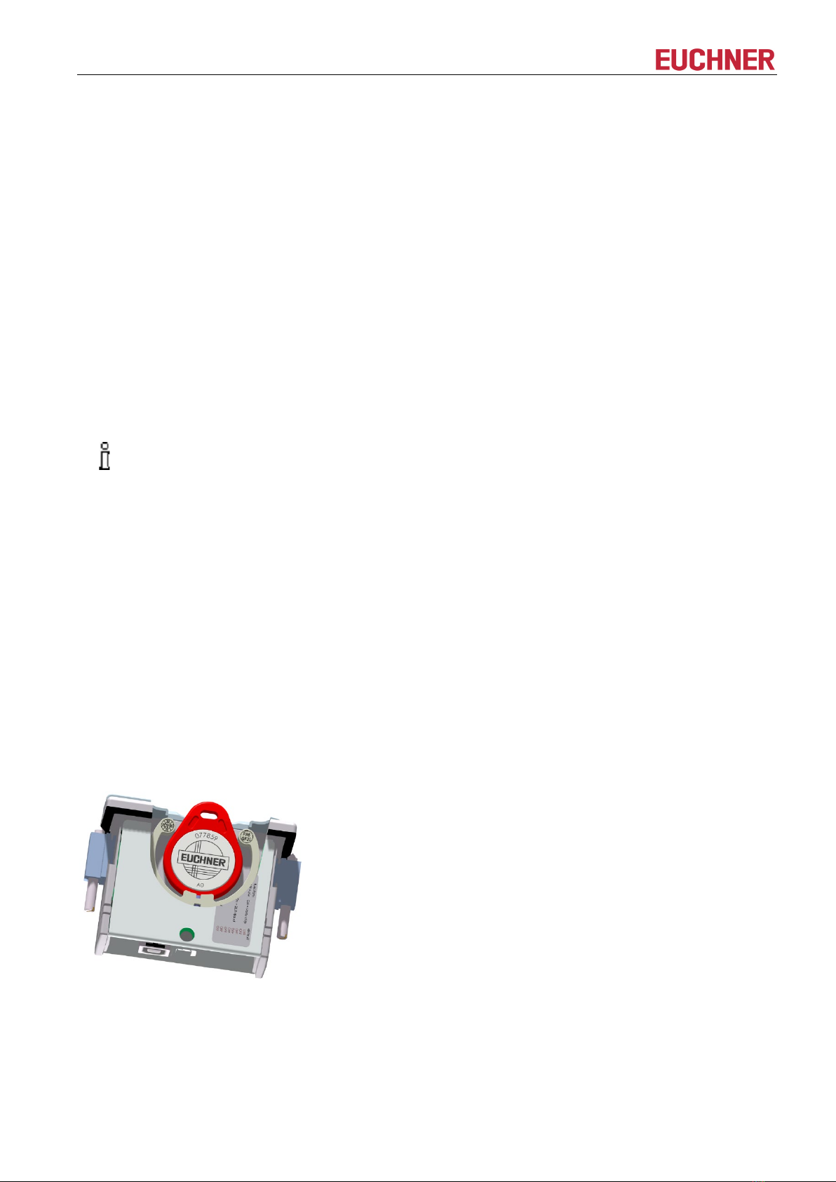
Product description: Electronic-Key-System Compact
FCC ID: 2AJ58-15
IC ID: 22052-15
Product description: Electronic-Key-System Modular
FCC ID: 2AJ58-16
IC ID: 22052-16
FCC/IC-Requirements
This device complies with part 15 of the FCC Rules and with Industry Canada’s licence-exempt RSSs.
Operation is subject to the following two conditions:
1) This device may not cause harmful interference, and
2) this device must accept any interference received, including interference that may cause undesired operation.
Changes or modifications not expressly approved by the party responsible for compliance could void the user‘s
authority to operate the equipment.
NOTE: This equipment has been tested and found to comply with the limits for a Class A digital device,
pursuant to part 15 of the FCC Rules. These limits are designed to provide reasonable protection against
harmful interference when the equipment is operated in a commercial environment. This equipment generates,
uses, and can radiate radio frequency energy and, if not installed and used in accordance with the instruction
manual, may cause harmful interference to radio communications.
Operation of this equipment in a residential area is likely to cause harmful interference in which case the user
will be required to correct the interference at his own expense.
Le présent appareil est conforme aux CNR d’Industrie Canada applicables aux appareils radio exempts de
licence. L’exploitation est autorisée aux deux conditions suivantes :
(1) l’appareil ne doit pas produire de brouillage, et
(2) l’utilisateur de l’appareil doit accepter tout brouillage radioélectrique subi, même si le brouillage est
susceptible d’en compromettre le fonctionnement.
1.4 Correct use
As part of a higher-level overall system, the EKS read/write station is used for access control and monitoring on
control systems or parts of control systems for machine installations. EKS can be used, for example, as part of
an overall system for checking access rights on the selection of the operating mode. However, it is not permitted
to derive the operating mode directly from the access rights on the Electronic-Key. If the selection of the
operating mode is relevant for safety, this must not be performed by means of the EKS; instead an additional
device must be used to select the operating mode.
Information!
The Machinery Directive 2006/42/EC provides
information on selection of the operating mode. It is
imperative that this information be followed.
When designing machines and using the read/write station, the national and international regulations and
standards specific to the application must be observed, e.g.:
EN 60204, Safety of machinery – Electrical equipment of machines
EN 12100-1, Safety of machinery – Basic concepts, general principles for design – Part 1: Basic
terminology, methodology
EN 62061, Safety of machinery – Functional safety of safety-related electrical, electronic and programmable
electronic control systems
EN ISO 13849-1, Safety of machinery – Safety-related parts of control systems – Part 1: General principles
for design
Modifications to the electronics of the read/write station and any other changes, especially mechanical
modifications and reworking, are not permissible and will result in the loss of the warranty and exclusion of
liability.

Manual EKS Ethernet TCP/IP
2547185-01-10/22 Subject to technical modifications Page 7/38
The read/write station must be employed and used only in accordance with
this manual and
other documentation referred to in this manual.
The EKS read/write station is not a safety component in the sense of the Machinery Directive.
Without additional precautions the EKS read/write station must not be used to provide a safety function,
particularly if failure or malfunction of the device could endanger the safety or health of people in the operating
area of a machine.
1.5 Obligations on the operating organization
The manufacturer and the organization operating the higher-level overall system, e.g. a machine installation, are
responsible for the observance of national and international safety and accident prevention regulations
applicable in the specific case.

Manual EKS Ethernet TCP/IP
Page 8/38 Subject to technical modifications 2547185-01-10/22
2 Safety precautions
Warning!
The
EKS read/write station is not a safety component in the sense of the Machinery Directive.
Without additional precautions the
read/write station must not be used to provide a safety function,
particularly if failure or malfunction of the device could endan
ger the safety or health of people in the
operating area of a machine. On this topic, pay particular attention to the sections
Correct use (see
chapter
1.4) and Electrical connection (see chapter 6).
Warning!
Mounting and electrical connection are allowed to be performed only by authorized personnel who are
familiar with the applicable regulations on accident prevention and have read and understood this
manual.
Furthermore, mounting and electrical connection o
f the version EKS FSA must be performed only by
personnel familiar with handling safety components.
Caution!
Modifications to the electronics of the
read/write station and any other changes, especially mechanical
modifications and reworking, are not permissible and will result in the loss of the warranty.

Manual EKS Ethernet TCP/IP
2547185-01-10/22 Subject to technical modifications Page 9/38
3 Function
3.1 Functional description
3.1.1 Common functions of EKS Standard and version EKS FSA
The EKS is used for access control and monitoring on control systems or parts of control systems for machine
installations.
Instead of passwords, coded Electronic-Keys are assigned. In this way unauthorized access to control and
visualization systems is prevented to the greatest possible extent.
The EKS uses a non-contact, inductive read/write identification system.
It comprises:
Electronic-Key
Electronic-Key adapter EKS compact or Electronic-Key adapter FHM with interface adapter EKS modular
The user is responsible for organizing the programming of the application, integration into an overall system and
the assignment and use of the freely programmable memory in the Electronic-Key.
Information!
For easier organization and management of your Electronic
-
Keys and the data they contain, EUCHNER
also offers the Electronic
-Key-Manager EKM software. To enter data in the EKM software, an
Electronic
-Key adapter with serial interface or USB interface must be in operation on the PC.
EKS Ethernet TCP/IP devices are read/write systems with electronics for the inductive bidirectional interface to
the transponder and interface electronics.
Due to the non-contact transfer of data, the Electronic-Key adapter is designed with a high degree of protection
suitable for industry from the access side. The Electronic-Key adapter is fastened from the rear side of the panel
in order to exclude unauthorized tampering from the operator side.
The system is connected via the Ethernet TCP/IP interface, which is designed as an RJ45 socket. A separate
switch may be required for the Ethernet TCP/IP connection. The device does not have an integrated switch.
Setup and system integration can be implemented straightforwardly and quickly on the read/write station with
Ethernet TCP/IP interface.
The current state of the Electronic-Key adapter is displayed using a 3-color LED.
The Electronic-Key is placed on the Electronic-Key adapter for operation. The power supply for the transponder
and the data are transferred between the Electronic-Key adapter and the Electronic-Key without using any
contacts.
Figure 1: Cut-away illustration of an Electronic-Key adapter with Electronic-Key in the compact version

Manual EKS Ethernet TCP/IP
Page 10/38 Subject to technical modifications 2547185-01-10/22
Figure 2: Illustration of an Electronic-Key adapter with Electronic-Key in the modular version
The Electronic-Keys are tag shaped. The complete transponder with memory chip and antenna is integrated
into the Electronic-Key. The transponder does not have a battery.
The data carrier in the Electronic-Key is equipped with a combined memory:
116 bytes E2PROM (programmable) plus 8 bytes ROM (serial number)
The programmable memory of 116 bytes is organized in 4-byte blocks. This means a multiple of 4-byte-sized
blocks must always be written.
3.1.2 Additional functions of the version EKS FSA
The version EKS FSA has additional switching contacts (semiconductor relay) that are switched off as long as
there is no Electronic-Key in the Electronic-Key adapter or if the Electronic-Key cannot be read.
Device in compact version: switching contacts LA1/LA2 and optionally LB1/LB2
Modular version of the device: only switching contact LA1/LA2
The switching contacts are electrically isolated from the device electronics and from each other. Either AC or
DC can be switched.
Each of the contacts is operated with diversity by a dedicated processor that opens the contacts on removal of
the Electronic-Key (see figure Block diagram EKS FSA).
Figure 3: Block diagram EKS FSA
Due to separate evaluation of channel LA and channel LB, the EKS FSA device can be used in conjunction with
a safe evaluation device in safety-related applications. Integrated voltage monitoring switches off the switching
contacts LA and LB if the power supply is outside the permitted tolerance (see chapters 4.4 and 4.5).
Information!
The switching contacts
FSA close when the Electronic-
Key is in place, irrespective of the data allocation
in the memory.

Manual EKS Ethernet TCP/IP
2547185-01-10/22 Subject to technical modifications Page 11/38
4 Technical data
4.1 Dimension drawing of Electronic-Key adapter compact
For installation in a control panel, you must provide a cut-out measuring 33 mm x 68 mm according to
DIN IEC 61554.
4.1.1 Version EKS-A-IEX-G01-ST02/03 with Ethernet interface
4.1.2 Version EKS-A-IEXA-G01-ST02/03/04 (EKS FSA) with Ethernet interface

Manual EKS Ethernet TCP/IP
Page 12/38 Subject to technical modifications 2547185-01-10/22
4.2 Dimension drawing of FHM Electronic-Key adapter modular
4.3 Dimension drawing of Ethernet TCP/IP modular interface adapter

Manual EKS Ethernet TCP/IP
2547185-01-10/22 Subject to technical modifications Page 13/38
4.4 Technical data for compact version
Attention!
All the electrical connections must either be isolated from the mains supply by a safety transformer
according to EN IEC 61558
-2-6 with limited output voltage in the event of a fault, or by other equivalent
isolation measures.
General parameters
Value
Unit
min.
typ.
max.
Housing
Plastic (PA 6 GF30, gray)
Degree of protection
IP65/IP67 in installed state
Ambient temperature at UB = DC 24 V
0
+ 55
°C
Mounting cut-out acc. to DIN IEC 61554
33 x 68
mm
Power supply connection
Plug-in connection terminal, 3-pin, with screw terminal
(tightening torque 0.22 Nm),
conductor cross-section 0.14 ... 1.5 mm²
Operating voltage U
B
(regulated, residual ripple < 5 %)
20 24 28 DC V
Current consumption IB
150
mA
Interface, data transfer
Interface to the control system
Industrial Ethernet (IEEE 802.3)
Transfer protocol
TCP/IP
Data transfer rate (full duplex)
10/100
Mbit/s
Connection for Ethernet interface
1 x RJ45 socket
Data line
2 x 2 twisted-pair copper cables, screened; min. category 5
Cable length
100
m
LED indicator
Green: “Ready” (in operation)
Yellow: “Electronic-Key active” *
Red: “Fault”
Version FSA (For Safety Applications) – parameters for floating semiconductor switching contacts LA and LB
Switching contact connection
Plug-in connection terminal, 4-pin, with screw terminal
(tightening torque 0.22 Nm),
conductor cross-section 0.14 ... 1.5 mm²
Power supply U for load (LA, LB)
24
30
V
Switching current (with overload protection)
1
10
50
mA
Output voltage UA(LA, LB) in switched state
U x 0.9
U
V
Resistance in switched state
35
ohms
Max. capacitive load
1
µF
Utilization category acc. to AC-12
EN IEC 60947-5-2 AC-15
DC-12
DC-13
50 mA / 24 V
Difference time of the outputs** (LB first)
200
ms
Reliability values acc. to EN ISO 13849-1 (FSA version only)
Category (with downstream safe evaluation)
3
MTTF
D
Evaluation of data channel and one
switching contact LA
416 years
Evaluation of data channel and both
switching contacts LA and LB
803 years
DC
92
%
* The LED illuminates yellow if there is a functional Electronic-Key in the Electronic-Key adapter.
** If the Ethernet interface is accessed during placement or removal of the Electronic-Key,
the difference time can be more than 200 ms.

Manual EKS Ethernet TCP/IP
Page 14/38 Subject to technical modifications 2547185-01-10/22
4.5 Technical data for modular version
Attention!
All the electrical connections must either be isolated from the mains supply by a safety transformer
according to EN IEC 61558
-2-6 with limited output voltage in the event of a fault, or by other equivalent
isolation measures.
General parameters
Value
Unit
min.
typ.
max.
General parameters of Electronic-Key adapter Front Hook Modular FHM
Housing
Plastic (PVDF GF20, gray)
Degree of protection
IP65/IP67/IP69K in installed state
Ambient temperature
-20
+70 / +100*
°C
Mounting bore
∅22.5
mm
Connection
Connection cable permanently connected to Electronic-Key
adapter or with plug connector in the cable, with flying lead
Connecting cable length
2, 5, 10, 15
m
Connecting cable cross-section
4 x 0.25 screened
mm²
Connecting cable outer sheath
PVC
General parameters of modular interface adapter
Housing
Plastic (PA 6.6, gray)
Ambient temperature at UB= DC 24 V
0
+55
°C
Mounting
35-mm mounting rail acc. to DIN EN 60715 TH35
Number of connectible Electronic-Key
adapters
1
Connection for power supply and Electronic-
Key adapter
Plug-in connection terminals, 4-pin and 5-pin,
with screw terminal (tightening torque 0.22 Nm)
or spring terminal, conductor cross-section 0.2 ... 1.5 mm²
Cable length to Electronic-Key adapter
2
15
m
Operating voltage U
B
(regulated, residual ripple < 5 %)
20 24 28 DC V
Current consumption IB
150
mA
Interface, data transfer
Interface to the control system
Industrial Ethernet (IEEE 802.3)
Transfer protocol
TCP/IP
Data transfer rate (full duplex)
10/100
Mbit/s
Connection for Ethernet interface
1 x RJ45 socket
Data line
2 x 2 twisted-pair copper cables, screened; min. category 5
Cable length
100
m
LED indicator read head
Green (STATE): "Ready" (in operation)
Yellow (ACTIVE): "Electronic-Key active" **
Red (DIA): "Error"
LED indicator Ethernet TCP/IP
Green (ON): "Active"
Red (CF): "Connection error"
Version FSA (For Safety Applications) – parameters for floating semiconductor switching contact LA
Switching contact connection
Plug-in connection terminal, 5-pin,
with screw terminal (tightening torque 0.22 Nm)
or spring terminal, conductor cross-section 0.2 ... 1.5 mm²
Power supply U for load (LA)
24
30
V
Switching current (with overload protection)
1
10
50
mA
Output voltage UA(LA) in switched state
U x 0.9
U
V
Resistance in switched state
35
ohms
Max. capacitive load
1
µF
Utilization category acc. to AC-12
EN IEC 60947-5-2 AC-15
DC-12
DC-13
50 mA / 24 V
Reliability values acc. to EN ISO 13849-1 (FSA version only)
Category (with downstream safe evaluation)
3
MTTF
D
Evaluation of data channel and one
switching contact LA
416 years
DC
92
%
*
This is not an ambient temperature for operation. It is valid for a time of no more than 3 minutes, e.g. for cleaning purposes.
**
The LED illuminates yellow if there is a functional Electronic-Key in the Electronic-Key adapter

Manual EKS Ethernet TCP/IP
2547185-01-10/22 Subject to technical modifications Page 15/38
4.6 Connector assignment
4.6.1 Connection socket for Ethernet interface
The connection on the read/write station is realized as an RJ45 (8P8C) socket corresponding to ISO IEC 61754-
24.
Pin
Function
1
Transmit Data + (TD+)
2
Transmit Data - (TD-)
3
Receive Data + (RD+)
6
Receive Data - (RD-)
4.6.2 Connection terminal assignment for compact version
Information!
The plug-in connection terminals are included with the Electronic-Key adapter.
Illustration shows version FSA
4.6.2.1 Connection of power supply
1 2 3
Plug-in connection terminal, 3-pin,
with screw terminal
Pin Designation Function
1 UB Power supply DC + 24 V
2 0V Power supply DC 0 V
3 Functional
earth Electrically connected to the housing
4.6.2.2 Plug-in screw terminals for outputs LA1/LA2 and LB1/LB2 (EKS FSA only)
Plug-in connection terminal,
2 x 2-pin,
with screw terminal
Pin Channel Function
1
LA NO contact, channel LA
2
3
LB NO contact, channel LB
4

Manual EKS Ethernet TCP/IP
Page 16/38 Subject to technical modifications 2547185-01-10/22
4.6.3 Connection terminal assignment for modular version
Information!
The plug-in connection terminals are not included with the interface adapter
4.6.3.1 Connection to Electronic-Key adapter
Plug-in connection terminal,
5-pin,
with screw terminal or spring
terminal
Pin Designation Function Conductor
coloring
1 SH Shield of FHM Electronic-Key
adapter BK
2 LED1 LED of FHM Electronic-Key
adapter YE
3 LED2 LED of FHM Electronic-Key
adapter GN
4 H2
Antenna of FHM Electronic-Key
adapter
WH
5 H1
Antenna of FHM Electronic-Key
adapter
BN
4.6.3.2 Connection of power supply
Plug-in connection terminal,
4-pin,
with screw terminal or spring
terminal
Pin Designation Function
1 0V Power supply DC 0 V
4 UB Power supply DC + 24 V

Manual EKS Ethernet TCP/IP
2547185-01-10/22 Subject to technical modifications Page 17/38
4.6.3.3 Connection of switching contact LA1/LA2 (EKS FSA only)
Plug-in connection terminal,
5-pin,
with screw terminal or spring
terminal
Pin Designation Function
1
2
3 LA1
NO contact, channel LA
4 0V
5 LA2

Manual EKS Ethernet TCP/IP
Page 18/38 Subject to technical modifications 2547185-01-10/22
4.7 DIP switch settings
The device has three DIP switches (S1, S2, S3).
Compact device
DIP switch
Function
S1
(4-fold)
S1.1 … S1.4; write and read settings
S2
(8-fold)
S2.1 … S2.8; setting of a fixed DNS name (required only for special applications)
S3
(4-fold)
S3.1 … S3.4; settings for network connection and service
Modular device
DIP switch
Function
S1
(4-fold)
S1.1 … S1.4; write and read settings
S2
(10-fold)
S2.1 … S2.10; setting of a fixed DNS name (required only for special applications)
S3
(4-fold)
S3.1 … S3.4; settings for network connection and service
Information!
The settings are adopted only when the power supply is switched on.
4.7.1 DIP switch S1
DIP
switch
Function Factory setting
S1.1
ON = write protection for Electronic-Key read/write
OFF
S1.2
No function
OFF
S1.3
No function
OFF
S1.4
No function
OFF
Information!
It is
imperative that all DIP switches without a function (S1.2, S1.3 and S1.4) are set to OFF! In this
way problems with any functions added in the future will be avoided.

Manual EKS Ethernet TCP/IP
2547185-01-10/22 Subject to technical modifications Page 19/38
4.7.2 DIP switch S2
DNS
name
LSB
S2.1
S2.2
S2.3
S2.4
S2.5
S2.6
S2.7
MSB
S2.8
S2.9*
S2.10*
EKS000
OFF
OFF
OFF
OFF
OFF
OFF
OFF
OFF
OFF
OFF
EKS001
ON
OFF
OFF
OFF
OFF
OFF
OFF
OFF
OFF
OFF
EKS002
OFF
ON
OFF
OFF
OFF
OFF
OFF
OFF
OFF
OFF
EKS003
ON
ON
OFF
OFF
OFF
OFF
OFF
OFF
OFF
OFF
…
…
…
…
…
…
…
…
…
…
…
EKS254
OFF
ON
ON
ON
ON
ON
ON
ON
OFF
OFF
EKS255
ON
ON
ON
ON
ON
ON
ON
ON
OFF
OFF
* Only if modular interface adapter fitted. Internal function. Retain default setting.
Information!
Using the DIP switch S2, it is possible to set an EKS name that is used for addressing the device in the
network in conjunction with a DHCP server. This name consists of the fixed code EKS plus a
configurable number between 001 and 255 that ca
n be used in all system environments with DHCP
support. The station name for a specific
read/write station would then be EKS027, for example.
The DIP switch S2 is relevant specifically in conjunction with the Siemens SINUMERIK DHCP address
assignment routi
ne (see chapter 6.1.1.3 Operation in the Siemens system network).
In this way it is possible to set the identical address by copying the DIP switch settings if a device is
replaced.
4.7.3 DIP switch S3
Function
S3.1
S3.2
S3.3
S3.4
Fixed IP address
OFF
OFF
OFF
Default IP address 192.168.1.1
OFF
ON
OFF
Obtain IP address from DHCP server
OFF
OFF
ON
Obtain IP address from a SINUMERIK control system
OFF
ON
ON
Internal function, leave switch OFF
OFF
Permit configuration via the web interface
OFF
OFF
OFF
OFF
(Factory setting: all in OFF position)
= any switch position
Information!
The use of the DIP switches to assign the IP address is described in the following in chapter
6.1.1.
To prevent unauthorized changes to the network, it is sensible to deactivate the web interface after use.
For this purpose switch S3.1 is set to ON.

Manual EKS Ethernet TCP/IP
Page 20/38 Subject to technical modifications 2547185-01-10/22
4.8 Indicator LED of compact version
The Electronic-Key adapter operating states are indicated using a three-color LED on the front.
The illumination of the LED in any color indicates the presence of the operating voltage.
Operating state
Description
Color
Electronic-Key
adapter power-up
or fault
After the application of the power supply, the LED is constantly illuminated red
during power-up. The completion of the process is indicated by a change in this
state after approx. 10 seconds. If the LED then flashes red quickly, it is an indication
of a network fault.
Red
Ready
Network connected.
Green
Electronic-Key
active
Network connected. Electronic-Key is in the Electronic-Key adapter. Yellow
Acknowledgment
As soon as the voltage is applied LED flashes red/green. Default IP address is
restored.
Red/green
4.9 Indicator LEDs of modular version
The operating states of the read/write stations are indicated via LEDs in three colors.
On the FHM Electronic-Key adapter, the state of the identification system is signaled by a single three-color
LED. On the interface adapter, the same state is signaled by three individual LEDs (read head) in different
colors. The illumination of the LED in any color indicates the presence of the operating voltage.
The state of the data interface is additionally signaled via two individual LEDs in different colors on the interface
adapter (Ethernet TCP/IP).
Ethernet TCP/IP
Read head
Operating state
Description
Green
ON
Red
CF
Green
STATE
Yellow
ACTIVE
Red
DIA
Power-up of the interface adapter
flashing
(2 Hz)
x* x x x
Malfunction: Ethernet TCP/IP error
on
on
x
x
x
Malfunction: Error in EKS (no Electronic-Key in
place)
on x flashing off flashing
Malfunction: Error in EKS (Electronic-Key in
place)
on x flashing flashing off
Ready: Network connected
on
off
on
off
off
Electronic-Key active: Network connected.
Electronic-Key is in the Electronic-Key adapter
on off on** on off
Acknowledgment: Default IP address is
restored
flashing
(1 Hz)
flashing
(1 Hz)
x x x
* x = Any state
** Only the yellow LED is illuminated on the FHM Electronic-Key adapter
This manual suits for next models
5
Table of contents
Other EUCHNER Industrial Equipment manuals
Popular Industrial Equipment manuals by other brands

Danfoss
Danfoss ET6110 Operator's manual

SCHUNK
SCHUNK RPE 100 Assembly and operating manual

Sentry
Sentry Saf-T-Vise STV-LP1 Installation, operation & maintenance manual

Formax
Formax PowerMax 3000 operating manual

Siemens
Siemens 411625A00 installation instructions

Loepfe
Loepfe YARNMASTER ZENIT+ quick guide