110124-3007A October-2010
Features
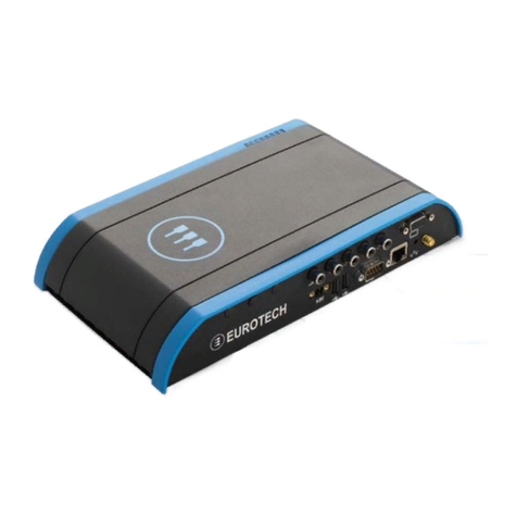
USB Bay
•To open the hinged USB Bay cover, remove the two
screws using the supplied tool.
•Do not forcibly pull on the USB devices to disconnect.
The USB ports in the USB Bay use sockets with
locking latches. Raise the latch on the socket to
remove the device.
Indicator LEDs
The system has eight red/green/yellow LEDs with the
following assignments:
LED Description
1 Power
Software-definable, SMBus
8 Boot-mode Button State
Ethernet
Network settings are configured to operate with a DHCP
server. To connect to your network, connect your network
cable to the Ethernet socket.
Switch
The system includes a momentary push-button switch
accessible through a small hole on the rear panel. This
switch generates an interrupt to the processor and is
software-definable.
Options
Optional Hardware
The Helios platform’s flexible design supports several
options, enabling many possible combinations to meet
your system requirements. Your development kit may
include one or more of the following optional functions:
•ZigBee
•Cellular modem with antenna connector
•WiFi with antenna connector
•EIA-485 serial port
•Vehicle-rated power input
Everyware™Software Framework
The Helios platform is available with the Everyware
Software Framework (ESF). Information about Eurotech’s
ESF is available at
http://esf.eurotech.com/
Technical Support
The Eurotech support site includes errata reports, the
latest releases of documents, and developer’s forums.
These resources are available to registered developers at:
http://support.eurotech-inc.com/
Next Steps
For additional information about the Helios platform,
download the Helios Platform Hardware Reference Manual
(Eurotech document #110124-3000) from the support site
or contact your local sales representative.
Contact Us
EUROTECH
Toll-free +1 888.941.2224
Tel. +1 301.490.4007
Fax +1 301.490.4582
E-mail: sales.us@eurotech.com
E-mail: support.us@eurotech.com
Web: www.eurotech-inc.com
