Eurovema Euroflex Flexmobil i6 User manual

1
User Manual
English
Flexmobil i6
part. no. BRU-i600-02 rev: 04/2021

2
Contents
Page
3. Introduction, use, test specication, and contact and product information.
4. Unpacking, assembly, and transport
5. Safety instructions
6. Overview of dierent seat systems
7. Overview, Flexmobil i6 SitRite
8. Overview, Flexmobil i6 Comfort
9. Control system, Linx REM211 and R-net
10. Back support, SitRite - seat depth and back support angle, manual setting.
11. Back support, Comfort - seat depth, manual line setting, and back support angle, electronic setting.
12. Back support, SitRite - height adjustment, manual setting.
13. Seat tilt, SitRite - manual setting and extra pelvis support
14. Waist belt - tting
15. Seat height, SitRite and Comfort - electronic setting
16. Seat tilt, SitRite and Comfort - electronic setting
17. Back support angle, SitRite and Comfort - electronic setting
18. Armrest - height and width adjustment
19. Control box holder - adjustment
20. Head rest, SitRite - adjustment
21. Head rest, Comfort - adjustment
22. Leg support - complete footplate
23. Leg support – split footplates
24. Leg support - electronic, adjustments
25. Operation, Linx / PG R-net
26. Operation training
27. Operation restrictions for inclined and uneven surfaces
28. Releasing the brakes
29. Circuit breaker/Power switch
30. Charging batteries
31. Warranty, service and CE marking
32. Care, maintenance, and cleaning
33. Technical data
34. Troubleshooting
35. Transport of electric wheelchair, lifting and attachment points
36. Moving the wheelchair user
37. Reconditioning, reusing, and scrapping
38. Source separation
39. Reconditioning checklist
If you are visually impaired: The User Manual is available in a PDF format that can be
magnied from www.eurovema.se/dokument.

3
INTRODUCTION
Congratulations on choosing a Flexmobil i6! We hope you will be pleased with this Euroex product from
Eurovema Mobility AB, which has been designed and built in Sweden. The electric wheelchair is designed
to satisfy very stringent demands in respect of ergonomics, sitting comfort, and function.
Read the User Manual carefully so that you can enjoy all the possibilities of your new i6!
USERS AND USE
Flexmobil i6 is and electrically-powered indoor wheelchair. It is designed for use by children and adults
with limited mobility and can be used by people who can handle a control device in a wheelchair. It is
strongly recommended that you are assessed by a physiotherapist, doctor, or other qualied and trained
person to determine whether the wheelchair is right for you. Flexmobil i6 is available in a variety of
dierent seat sizes, all of which have a number of setting options, allowing the chair to be customised to
your specic requirements. Expected product service life is 10 years.
TEST SPECIFICATION
Flexmobil i6 is CE marked and is compliant with applicable requirements set out in the Swedish Medical
Devices Act 1993:358 (93/42/EEC), as well as the Swedish Medical Products Agency's medical devices
regulations, LVFS 2013:11. It is compliant with all requirements of EN 12184:2014 Class A.
ASSOCIATED DOCUMENTS
Product data sheet, service manual, installation instructions, safety notices, and any product recalls can be
read and downloaded from www.eurovema.se

4
UNPACKING AND ASSEMBLY
- Open the packaging and check that it has not suered any damage during transit.
- Also check that the delivery corresponds with the order.
If the chair is supplied with the back support and armrests not tted:
• Press in the spring bearing and insert the back pillar as shown in the gure (1). Tighten the knob (2) and
screw the safety screw in the side of the back pillar (3, 4).
Before using for the rst time, check that
• all knobs and screws are tightened.
• the brake release mechanism has been deactivated.
• no visible cables are crushed or damaged.
• the armrests and back support are raised and do not touch the housing when the seat is in its lowest
position.
• the display shows no fault codes (no ashing lights).
• the battery is fully charged.
• joystick control works in all directions and that the wheelchair stops when the joystick is released
TRANSPORT
When transporting the chair in motor vehicles, it is important that the brakes are engaged. See section
“Releasing the brakes”. The chair should be strapped in place with straps. Special attachment lugs are tted
as standard. It is strictly forbidden to sit in the wheelchair whilst it is in transit. You can reduce the trans-
port dimensions of the chair by removing the back support, armrests, and leg support. The batteries in the
wheelchair are maintenance-free and sealed (AGM type), and are also approved for transport by air. For
more information about transport, see page 35.

5
SAFETY RULES
• Read the User Manual carefully before using the electric wheelchair.
• Charge the batteries as soon as possible when the battery light turns orange.
• The lifting pillar has a work cycle of 2 on /18 o, which means 2 minutes of use, followed by 18 minutes
of rest.
• The electric wheelchair is designed to be used in a normal indoor climate.
• Take care when adjusting the manual seat angle while sitting in the chair as there is a risk you could fall
out of the chair.
• If you nd damage, loose components, or changes in the chair's function, contact the service organisa-
tion (technical aid supplier) immediately.
• Using the various seat setting options may aect the stability of the wheelchair. Only use these options
when the wheelchair is standing on at ground.
• Make sure you tighten all the screws, knobs, and controls properly after making adjustments.
• Metal surfaces may get very hot if they are exposed to sunlight or some other external source of heat.
• Service, maintenance, and adaptations should be carried out by trained sta authorised by Eurovema
Mobility AB.
• When making repairs, only use original parts from Eurovema Mobility.
• Do not exceed the stated maximum user weight (150 kg).
• Only use the included original battery charger to charge the batteries.
• In order to maintain safety, only use original attachments for detachable parts, e.g. armrests, back sup-
port, and footplate.
• The functionality of the electric wheelchair maybe impaired in strong electromagnetic elds emitted by
things such as power cables and data centres. The wheelchair may cause interference to equipment based
on electromagnetic elds such as alarm systems in businesses, automatic doors, etc.

6
Overview of different seat systems
The Euroex seat system is designed to deliver optimal sitting comfort to the user. The
soft lled cushion is available in a variety of sizes and gives optimal sitting comfort and
support to the user. It is upholstered in a dirt-resistant and machine washable polyester
fabric.
The system is available in the following combinations:
1. SitRite
2. Comfort
3. Child ABC

7
Overview, Flexmobil i6 SitRite
1) control box
2) joystick
3) charging port
4) seat
5) back support
6) armrest
7) automatic fuse
8) drive wheel
9) battery cover
10) swivel wheels
11) footplate
12) seat lifting actuator
13) adjustment knob

8
Overview, Flexmobil i6 Comfort
1) control box
2) joystick
3) charging port
4) lifting pillar
5) back support
6) armrest
7) drive wheel
8) battery cover
9) swivel wheels
10) leg support

9
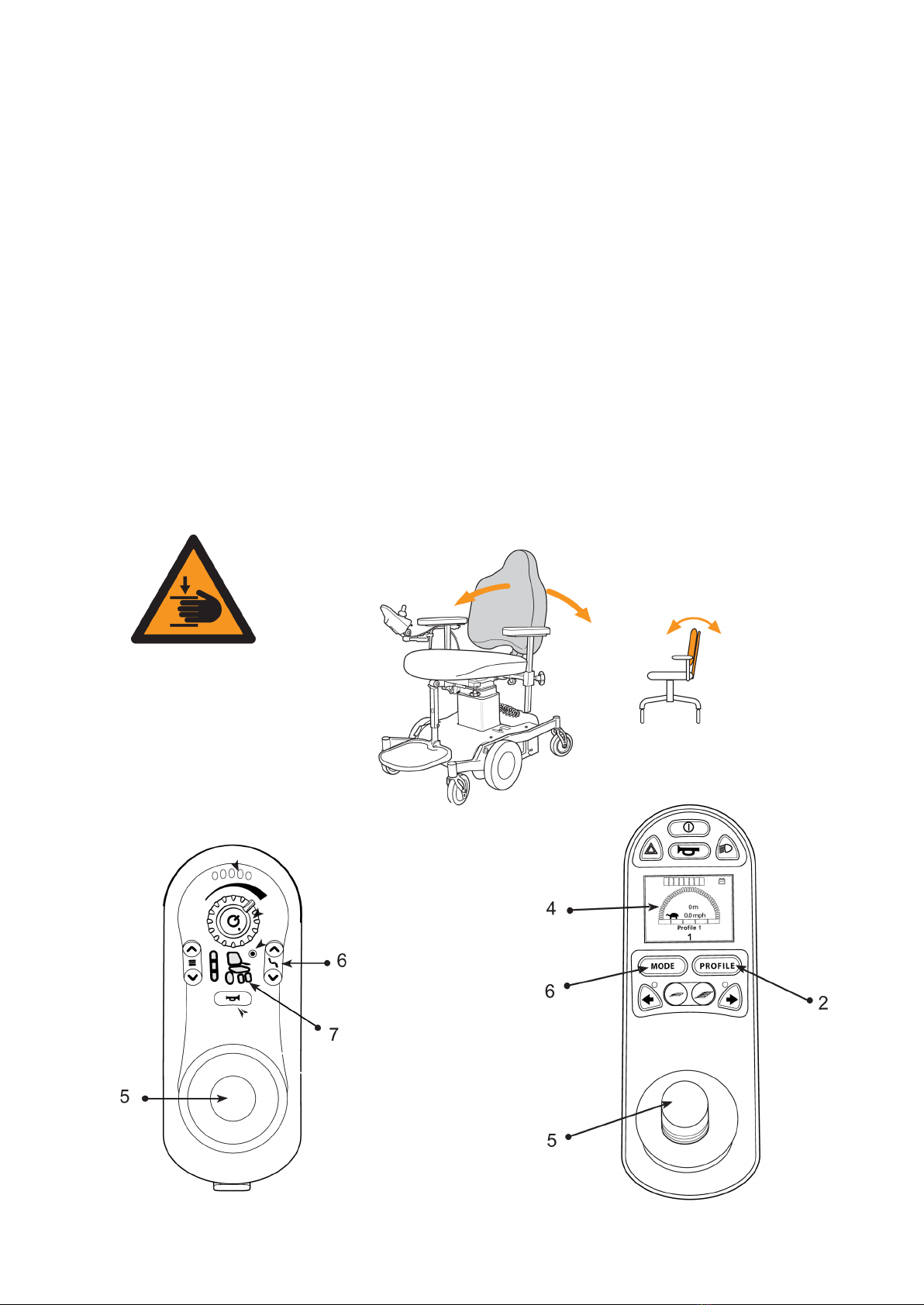
Control system, Linx REM211 and R-net
Flexmobil i6 is equipped with a control system from either Dynamics Control or PG Drive that controls the
power from the batteries to the motors.
The wheelchair and its electrical seat functions are controlled using the control box, which is available in
two dierent versions: Linx REM211 and R-net. The joystick is used to drive the wheelchair in the desired
direction. The electronics can be programmed and adapted to the individual user's requirements, but
usually the original program is perfectly adequate. Should any fault with the electronics arise, the on/o
button will ash red (1) Linx REM211. The fault can be identied by counting the number of ashes. See
chapter “Troubleshooting”.
1) on/o
2) operator prole selection
3) battery indicator
4) speed adjuster
5) joystick
6) seat function selection
7) seat function symbols
8) signal horn
9) operator program status
10) connection indicator
11) operation light (not used)
12) hazard warning lights
LINX REM211 PG R-net

10
BACK SUPPORT, SitRite - Seat depth, manual setting
Use the wheel (1) to adjust seat depth with back support. Set the desired seat depth by moving the back
support backwards or forwards. Move the wheel to its original position to lock.
BACK SUPPORT, SitRite– Back support angle, manual setting
Use the lever (2) to adjust the angle of the back support. Dial in the required angle and lock by moving the
lever back to its original position.
11
BACK SUPPORT, Comfort – Seat depth, manual setting
To adjust seat depth and back support: Undo the two hex screws holding the actuator in position and the
for hex screws holding the back support to the seat frame. Set the desired seat depth by moving the back
support backwards or forwards to the required position. Tighten the hex screws.
BACK SUPPORT, Comfort – Back angle, electronic setting.
To adjust the angle of the back support, use the control box. An illustration of the control box can be found
on page 9.
LINX REM211
Press the “seat function selection”button (6, see page 9) to access seat settings. Choose seat by moving the
joystick right or left until the back support symbol comes on. Then move the joystick forwards to adjust the
back support forwards, and backwards to adjust the back support backwards.
PG R-Net
Press the “MODE” button to access seat settings. Choose seat by moving the joystick right or left until the
back support symbol comes on. Then move the joystick forwards to adjust the back support forwards, and
backwards to adjust the back support backwards

12
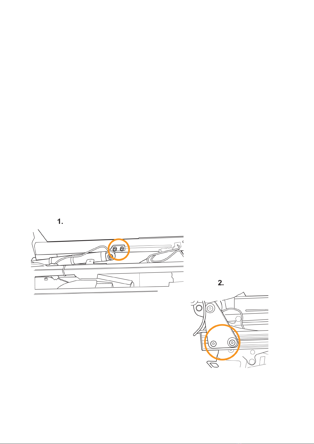
BACK SUPPORT, SitRite - height adjustment, manual setting
Undo the safety screws (3, 4) using an Allen key before adjusting the height of the back support (1).
Loosen the lever (2) by turning it anticlockwise a ½ turn. Set the back support to the desired height and
turn the lever ½ a turn clockwise to lock. After making the adjustment, tighten the safety screws (3, 4).
13
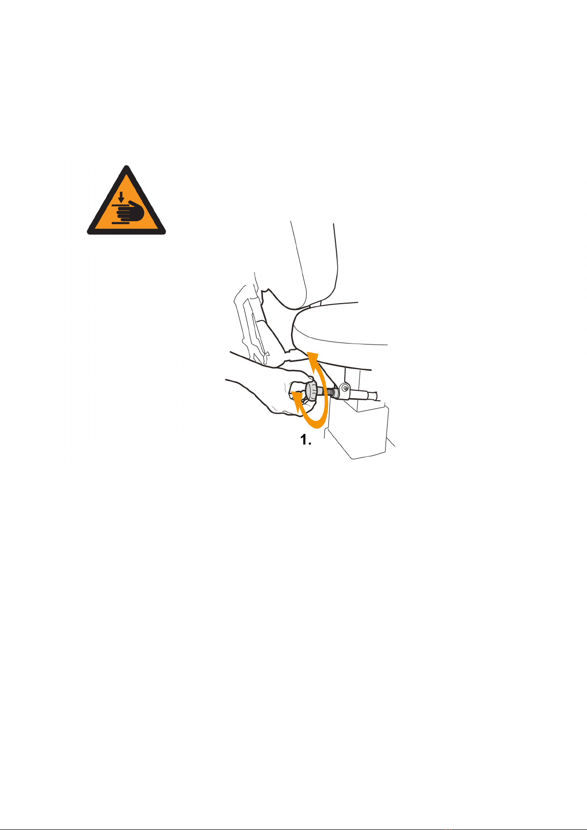
SEAT TILT, SitRite - seat angle, manual setting
The seat angle can be adjusted within a range of -14° to +32° backwards. Turn the wheel clockwise to tilt
the seat forwards, and anticlockwise to tilt backwards (1).
Extra pelvis support
To get good support for the pelvis and torso stability, we recommend the use of the SitRite seat system
together with a waist belt and thigh support. This seat has an economically integrated seat cavity that
prevents sliding and aords optimal pelvis positioning. This moves pressure from the pelvis to the thighs,
thereby reducing pressure on exposed areas of the body.
NB Risk of crushing
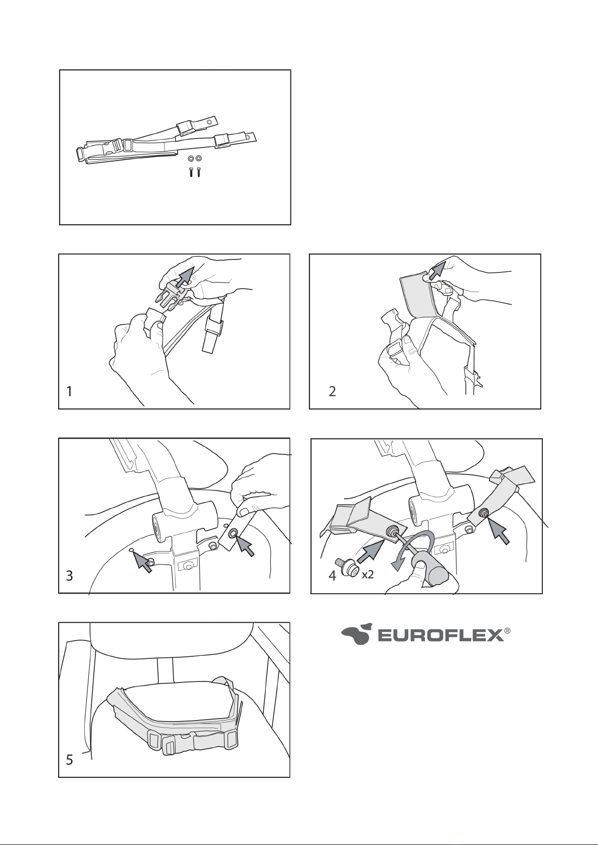
14
Installation instructions,
waist belt
Waist belt for adults, Item
80151800

15
SEAT HEIGHT, SitRite and Comfort - electronic setting
The seat can be raised and lowered steplessly to any height, and the selected hight will be automatically
locked in. Start the wheelchair electronics by pressing the on/o button (1).
LINX REM211
Select “seat lift symbol” (7) by pressing the up or down arrow in the select seat function button cluster
(6), or by moving the joystick (5) to the right or left until the “seat lift symbol” comes on. Then move the
joystick forwards to raise the seat, and backwards to lower the seat.
PG R-Net
Press the “MODE” button (6). Then move the joystick to the right or left until the seat lift symbol (4) comes
on. Then move the joystick (5) forwards to lower the seat, and backwards to raise the seat. The height
adjustment stops automatically once the joystick is released. To return to run mode, press the “PROFILE”
button (2) and the selected run program will be shown in the display (4).
LINX REM211 PG R-net
16
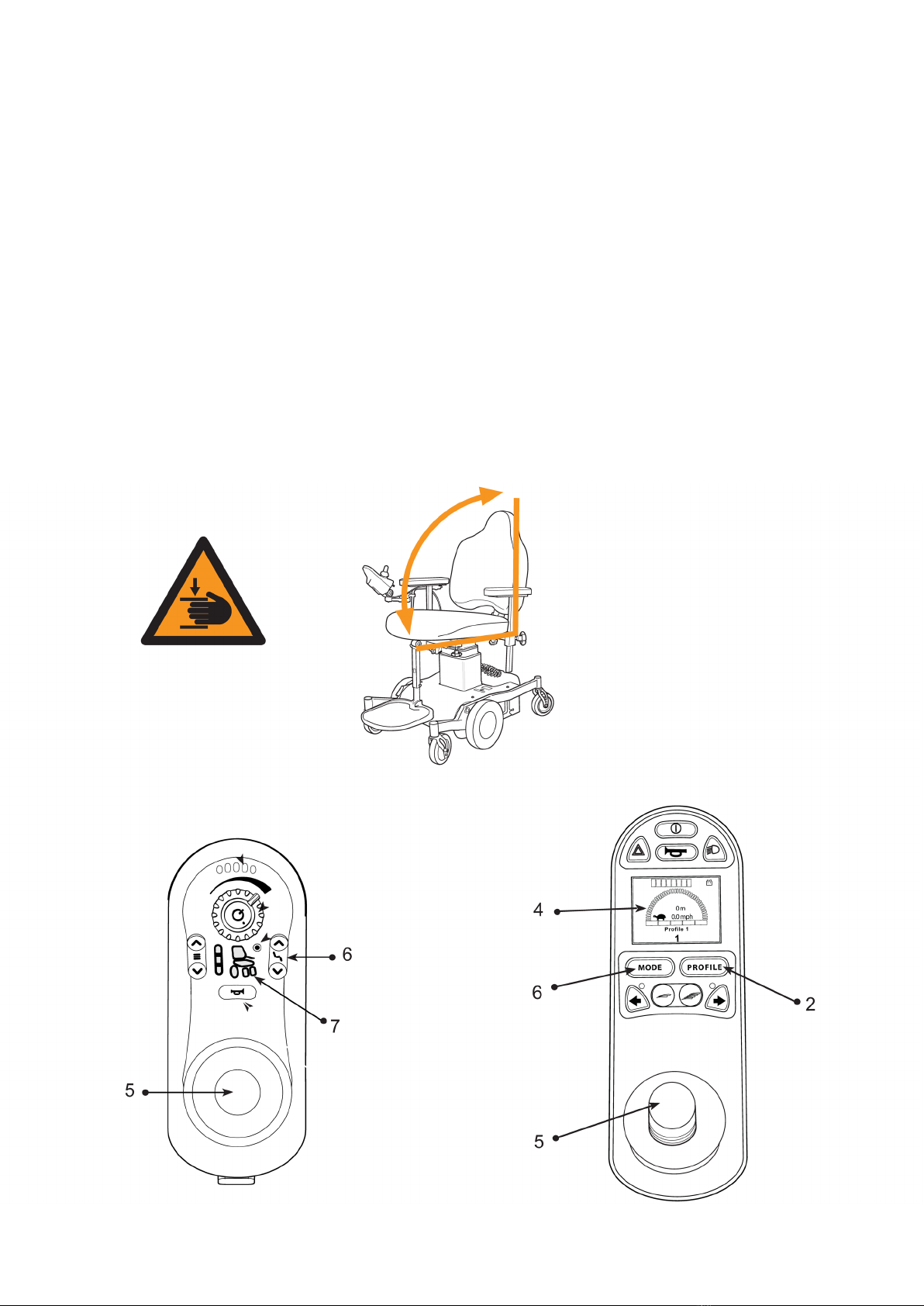
SEAT TILT, SitRite and Comfort - electronic setting
If the seat is equipped with electronic seat angling/tilt, this function is activated via the control box.
LINX REM211
Select “seat tilt” (7) by pressing the up or down arrow in the seat function button cluster (6), or by moving
the joystick (5) to the right or left until the“seat tilt symbol” light comes on. Then move the joystick
forwards to tilt the seat forwards, and backwards to tilt the seat backwards.
PG R-Net
Press the “MODE” button (6). Then move the joystick to the right or left until the seat tilt symbol light (4)
comes on. Then move the joystick (5) forwards to angle the seat forwards, and backwards to angle the seat
backwards. Seat angling stops automatically once the end positions are reached. To return to run mode,
press the “PROFILE” button (2) and the selected run program will be shown in the display (4).
NB Risk of crushing
LINX REM211 PG R-net
17
Back support angle, SitRite and Comfort - electronic setting
If the seat is equipped with electronic back support angling, this function is activated via the control box
LINX REM211
Select the “back support symbol” (7) by pressing the up or down arrow in the seat function button cluster
(6), or by moving the joystick (5) to the right or left until the back support symbol light comes on. Then
move the joystick (5) forwards to adjust the back support forwards, and backwards to adjust the back
support backwards.
PG R-Net
Press the “MODE” button (6). Then move the joystick (5) to the right or left until the back support
symbol light (4) comes on. Then move the joystick (5) forwards to adjust the back support forwards, and
backwards to adjust the back support backwards. Back support adjustment stops automatically once the
end positions are reached. To return to run mode, press the “PROFILE” button (2) and the selected run
program will be shown in the display (4).
NB Risk of crushing
LINX REM211 PG R-net

18
ARMREST - height and width adjustment
To adjust the width between the armrests, loosen the wheel (1). Adjust to the desired width and tighten
the wheel. Repeat the procedure for the other armrest. Adjust armrest height by loosening the lever (2).
Adjust to the desired height and tighten the lever.
ARMREST - backwards retractable
If the wheelchair is equipped with retractable armrests, they can be folded backwards to facilitate lateral
movement and enable the user to get closer to objects, e.g. a table. Press the lever down in the direction of
the arrow to retract the armrest backwards. To put the armrest back, lift it by hand to the upright position
where it is locked automatically.
NB Risk of crushing!

19
CONTROL BOX HOLDER - adjustment
The position of the control box can be adjusted by loosening the screws 1, 2and 3using a 5 mm Allen key.
Loosen screw 1to adjust depth, and screws 2and 3to adjust the angle and height of the control box. Set
the desired position and tighten the screws. The control box can also be moved to the side and backwards
in order to be out of the way when, for example, you want to get near to a table.
NB Risk of crushing!
20
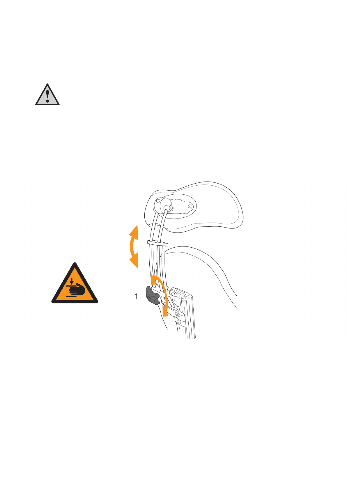
HEAD REST, SitRite - adjustment
If the chair is equipped with a head rest, the height can be adjusted by loosening the wheel (1). Set the
correct height and tighten the wheel.
WARNING - RISK OF CRUSHING!
When the wheel is loosened, the head rest becomes loose and can quickly fall down. Observe caution
when adjusting!
NB Risk of crushing!
Other manuals for Euroflex Flexmobil i6
3
This manual suits for next models
4
Table of contents
Other Eurovema Wheelchair manuals

Eurovema
Eurovema miniflex forma User manual

Eurovema
Eurovema 269101-4000H User manual

Eurovema
Eurovema DX 913 User manual

Eurovema
Eurovema Euroflex Miniflex SitRite User manual

Eurovema
Eurovema Euroflex Flexmobil i6 User manual

Eurovema
Eurovema Euroflex Flexmobil i6 User manual

Eurovema
Eurovema Euroflex Miniflex User manual

Eurovema
Eurovema Euroflex Flexmobil i6 User manual

Eurovema
Eurovema Euroflex Reflex User manual


