Everlast 16516896 User manual

RECUMBENT CYCLE
OWNER`S
MANUAL
Model No.
16516896
Recumbent
Cycle
CAUTION:
You must read and
understand this
owner’s manual
before operating unit.
Keep this manual for
future reference.

Customer Service 1-888-707-1880
1
TABLE OF CONTENTS
Manufacturer’s Limited Warranty ……………………. …… 2
Safety Precautions………….………………………………. 3
Before you begin …………………………………………….. 4
Pre-assembly Check List…………………………………… 5
Hardware Packing List……………………………………… 6
Assembly Instruction……………………………………….. 7-11
Monitor Instruction……...…………………………………… 12-15
User Direction………………………………………………. 16
Maintenance ………………………………………………… 17
Parts List / Diagram ………………………………………… 18-21
Troubleshooting …………………………………………….. 22
Training Guideline …………………………………………… 23-25
Stretching …………………………………………………….. 26-27

Customer Service 1-888-707-1880
2
Manufacture’s One-Year Limited Warranty
Your Everlast Cycle is warranted for one year from the date of purchase against defects in
material when used for the purpose intended, under normal conditions and provided it
receives proper care. Any part found defective or missing will be sent at no cost when
returned in accordance with the terms of this warranty.
This warranty is not transferable and is extended only to the original owner.
The warranty shall not apply to exercise units which are (1) used for commercial or other
income producing purposes, or (2) subject to misuse, neglect, accident or unauthorized
repair and alterations.
This warranty provided herein is lieu of all other express warranties, any implied warranties,
including any implied warranties of merchantability of fitness for particular purpose, are
limited in duration to the first 12 months from date of purchase. All other obligations or
liabilities, including liability for consequential damages are hereby excluded.
REPAIR PARTS AND SERVICE
All of the parts for the cycle shown in figure can be ordered from Dyaco Canada Inc.
6050 DON MURIE STREET, NIAGARA FALLS, ONTARIO L2G 0B3. When ordering parts,
the parts will be sent and billed at the current prices. Prices may be subject to change without
notice. Check or money order must accompany all orders. Standard hardware items are
available at your local hardware store.
To ensure prompt and correct handling of any errors, or to answer any questions, please call
our Toll Free number: 1-888-707-1880, or local number 1-905-353-8955 or fax 1-905-353-
8:30 AM to 5:00 PM Monday to Friday Eastern Standard Time.
Always include the following information when ordering parts
Model number
Name of each part
Part number of each part

Customer Service 1-888-707-1880
3
SAFETY PRECAUTIONS
Thank you for purchasing our product. Even though we go to great efforts to ensure the
quality of each product we produce, occasional errors and /or omissions do occur. In any
event should you find this product to have either a defective or a missing part please contact
us for a replacement.
This product has been designed for home use only. Product liability and guarantee conditions
will not be applicable to products being subjected to professional use or products being used
in a gym center.
This exercise equipment was designed and built for optimum safety. However, certain
precautions apply whenever you operate a piece of exercise equipment. Be sure to read the
entire manual before assembly and operation of this machine. Also, please note the following
safety precautions:
1. Read the OWNER’S OPERATING MANUAL and all warnings posted on the exercise cycle
and follow it carefully before using your cycle.
2. If dizziness, nausea, chest pains, or any other abnormal symptoms are experienced while
using this equipment, STOP the workout at once. CONSULT A PHYSICIAN
IMMEDIATELY.
3. Review all warnings labels that affixed to the cycle. Inspect your exercise equipment prior
to exercising to ensure that all nuts and bolts are fully tightened before each use.
Functional and visual inspection of the equipment shall be made after assembling your
cycle
4. The cycle must be regularly checked for signs of wear and damage. Any part found
defective must be replaced with a new part from the manufacturer.
5. Set up and operate the exercise bicycle on a solid level surface. It is recommended to use
an equipment mat to prevent the unit from moving while it is being used, which could
possibly scratch or damage the surface of your floor.
6. No changes must be made which might compromise the safety of the equipment.
7. It is recommended to have a minimum of 2’ safe clearance around the exercise equipment
while in use.
8. The pulse sensor is not a medical devise. Various factors, including the user’s movement
may affect the accuracy of the heart rate readings. The pulse
9. Keep children and pets away from this equipment at all times while exercising.
10. Warm up 5 to 10 minutes before each workout and cool down 5 to 10 minutes afterward.
This allows your heart rate to gradually increase and decrease and will help prevent you
from straining muscles.
11. Never hold your breath while exercising. Breathing should remain at a normal rate in
conjunction with the level of exercise being performed
12. Always wear suitable clothing and footwear while exercising. Do not wear loose fitting
clothing that could become entangled with the moving parts of your cycle.
13. Always hold the handlebars when mounting, dismounting or using the cycle. When you
stop exercising, allow pedals to slowly come to a complete stop before dismounting.
14. Care must be taken when lifting or moving the equipment, so as not to injure your back.
Always use proper lifting techniques.
15. User weight should not exceed 275lbs.
16. Tie all long hair back.
17. Remove all personal jewellery before exercising.
18. After eating, allow 1-2 hours before exercising as this will help to prevent muscle strain.
19. Injuries may result from incorrect or excessive training and using the equipment
otherwise than as directed or recommended by your doctor
WARNING: Before beginning any exercise program consult your physician. This
is especially important for individuals over the age of 35 or persons with pre-existing
health problems. Read all instructions before using any fitness equipment. We
assume no responsibility from personal injury or property damage sustained by or
through the use of this product.
SAVE THESE INSTRUCTIONS

Customer Service 1-888-707-1880
4
BEFORE YOU BEGIN
Thank you for selecting the revolutionary Everlast exercise bike. Cycling is an effective
exercise for increasing cardiovascular fitness, building endurance, and toning the body. The
exercise bike provides an impressive selection of features designed to make your workouts
at home more effective and enjoyable.
For your benefit, read this manual carefully before you use the exercise bike. If you
have questions after reading this manual, please see the front cover of this manual. To help
us assist you, note the product model number and serial number before contacting us. The
model number and the location of the serial number decal are shown on the front cover of
this manual. Before reading further, please familiarize yourself with the parts that are labeled
in the drawing below
Hand pulse sensor
Quick release knob
Transport wheel
Computer
Left pedal w/strap
Stationary Handlebar
Back cushion
Seat cushion
End cap
Handlebar
Front post
Leveller

Customer Service 1-888-707-1880
5
PRE-ASSEMBLY CHECK LIST
71
73
44
69
84
72
1
73 275
NO.
Description
Quantity
1/2
F Front main frame / Rear main frame
1
8/29
Front stabilizer w/ transportation w heels
1
9
Rear stabilizer
1
31
End caps
2
4/59/80
Handlebar w/hand pulse sensor, hand pulse wire
1
7/78
Stationary handlebar w/foam grips
1
55
Back cushion
1
54/56
Seat cushion w/screws
1
6
Back cushion support post
1
32/68
Computer w/screws
1
41
Audio cable
1
37
Water bottle holder
1
3/83
Upright w/middle section system cable
1
38
Adaptor
1
Inner box
1


Customer Service 1-888-707-1880
7
ASSEMBLY INSTRUCTION
This manual is designed to help you easily assemble, adjust and use this machine. Please
read this manual carefully. For the sake of familiarizing yourself with the parts identified in the
instruction, first study the overview drawing.
Set all parts in a clear area on the floor and remove the packing material. Refer to the parts
list for help to identify the parts.
It will take two people to assemble your unit.
Note: If a part is not in the hardware kit, check to see if it has been preassembled. To
avoid damaging parts, do not use power tools for assembly.
STEP 1 ATTACH THE FRONT STABILIZER
1. Attach the front stabilizer (8) with two transportation wheels (29) to the front curved bracket of
the front frame (1). Secure using two carriage bolts (51), two curve washers (52), two spring
washers (48) and two cap nuts (53).
NOTE: Make sure you fasten the bolts securely to avoid shaking and discomfort when cycling.
71
73
44
69
84
72
1
73 275

Customer Service 1-888-707-1880
8
STEP 2 ATTACH THE REAR STABILIZER
1. Attach the rear stabilizer (9) to the welded bracket of the rear frame (2) and tighten with two allen
head bolts (47), two spring washers (48), two flat washers (49) at the bottom side of the rear
stabilizer (2).
2. Attach one rear stabilizer end cap (31) to the left side of the rear stabilizer (9) and tighten with
two screws (92) and one leveling cap (35).
3. Do the same procedure for right side end cap (31) and the rear stabilizer (9) assembly.
4. Connect the front section system cable (73) of the main frame (1) to the rear section system
cable (81) of the rear frame (2).
5. Insert the front frame (1) into the rear frame (2) and tighten with four allen head bolts (84), four
spring washers (50) and four curve washers (69) on both sides of the rear frame (2).
6. After that, please tighten with three allen head bolts (85) on the bottom side of the front frame
(1).
7. Tighten the leveling cap (44) on the bottom side of the front frame (1)
NOTE: Make sure you fasten the bolts securely to avoid shaking and discomfort when cycling.
NOTE: After the bike assembly is completed, please use the assembled two leveling caps (35)
to adjust the whole bike balance.
84
69
44
69
84
50
1
73 275

Customer Service 1-888-707-1880
9
STEP 3 ATTACH THE HANDLEBAR AND BACK CUSHION SUPPORT FRAME
1. Insert the back cushion support frame (6) to the seat post of the rear frame (2) and tighten with
four allen head bolts (40), four flat washers (49) on three sides of the seat support frame (5).
2. Attach the handlebar (4) with hand pulse to the welded curved bracket of the seat support frame
(5) and secure with two allen head bolts (90), two curve washers (52), and two spring washers
(48).
3. Insert the hand pulse wires (82) into the socket of the rear section system cable (81) of the rear
frame (2).
STEP 4 ATTACH THE SEAT AND BACK CUSHION
1. Remove the four pre-assembled bolts (56) from the back of the seat (54).
2. Attach the seat (54) to the two brackets of the seat support frame (5) and secure with four cross
head bolts (56).
3. Attach the back cushion (55) to the two welded screw holes of the back cushion support frame
(6). Secure using two allen head bolts (67).
54
567
2
5
67
40
49
40 2
4
90 48 52
81

Customer Service 1-888-707-1880
10
STEP 5 ATTACH THE UPRIGHT AND STATIONARY HANDLEBAR
1. Connect the hand pulse wire and motor cable of the front section system cable (73) to the middle
section hand pulse wire and motor cable of the system cable (83).
2. Attach the upright (3) to the bottom mount tube of the main frame (1) and secure with three
cross head bolts (56), three curve washers (30) and three spring washers (91) .
NOTE: Do not tighten the cross head bolts (56) until all of the bolts have been fastened. Ensure
that you do not pinch the wires when tightening the bolts.
3. Attach the stationary handlebar (7) to the welded curved bracket of the upright (3) and secure
with two carriage bolts (57), two curve washers (52), two spring washers (48) and two cap nuts
(53).
4. Attach the water bottle holder (37) to the two screw holes of the upright (3) and secure with two
machine screws (63).
56
56
91 30 91
83
30
56
3
73
1
57
53
48
52
63
37
STEP 6 ATTACH THE COMPUTER
1. Remove four pre-assembled round head screws (68) from the back of the computer (32).
2. Connect the motor cable and the hand pulse wire of the middle section system cable (83) to the
motor cable and hand pulse wire which are from the computer (32).
3. Attach the computer (32) to the top welded computer bracket of the upright (3) and secure with
four round head screws (68).
6. Insert the audio cable (41) to the MP3 socket of the computer (32).
NOTE: Do not tighten the cross head bolts (68) until all of the bolts have been fastened. Ensure
that you do not pinch the wires when tightening the bolts.
368
32
41
83

Customer Service 1-888-707-1880
11
STEP 7 ATTACH THE PEDAL, STRAPS AND ADAPTOR
1. Attach the right and left pedal straps (42R/L) to the right and left pedals (15R/L).
NOTE: The end with four adjustable holes must be set outwards.
2. Attach the right and left pedal (15R/L) to the right and left sides of the crank arms (11).
3. Plug the adaptor (38) into the socket of the power cable (39) located on the front chain cover of
the recumbent bike. Plug the adaptor (38) into a wall electrical outlet.
NOTE: The pedals and crank arms are marked with R & L. The right pedal should be threaded
on clockwise and the left pedal (L) should be threaded counter-clockwise.
15L
15L
15R
11
1
38
42L
ENSURE TO FIRMLY TIGHTEN ALL NUTS AND BOLTS
YOUR UNIT IS NOW FULLY ASSEMBLED
To listen to an MP3 during your workout, connect the MP3 with the computer by using the
audio wire.

Customer Service 1-888-707-1880
12
COMPUTER INSTRUCTIONS
BUTTONS:
▲/UP:Press to select programs P1 to P12. Press to increase the values of the
setting mode.
Press to increase the level of the workload when running a program.
▼/DOWN: Press to select programs P1 to P12. Press to decrease the values of the setting mode.
Press to decrease the level of the workload when running a program.
SET:Press to confirm the selected programs P1 to P12. Press the SET button to select the
values of the various settings.
START/STOP: Press to start the selected program. Press the START / STOP button to stop the
program. You can press the START / STOP button again to continue to run the current
program, or use “▲ / ▼ ”buttons to select a new program.
MODE: Press to select the function value displays of RPM and WATT, or SPEED and
CALORIES.
RESET: Press to reset all of the function values to zero.
FAN:Press to turn on or off, and to change the speed of the fan on the COMPUTER(27) in
sequence as follows: Low Speed →High Speed →OFF

Customer Service 1-888-707-1880
13
LCD DISPLAY INSTRUCTIONS
PROGRAM: Display programs for selection during setup, from P1 to P12. Displays the
selected program during exercise.
TIME: Displays the time. Counts upward from one second to 99:59 minutes. Counts
down from preset value.
SPEED/RPM: Displays the current speed from zero 99.9 miles per hour, or RPM from zero to
999 RPM. Press the MODE button to select the display of SPEED or RPM.
DISTANCE: Displays the distance from zero to 999.9 miles.
CALORIE/WATT: Displays the calorie consumption from zero to 999.9 WATT.
Press the MODE button to select the display of CAL or WATT.
NOTE: The calories and watt readouts are an estimate for an average user.
It should be used only as a comparison between workouts on this unit.
AGE: When you select the Heart Rate Control Programs, P11 or P12, you must input
your TARGET H.R.: age. This value affects only the Heart Rate Control
Programs. Press the SET button until the AGE/TARGET H.R. display is
flashing and uses the “▲ / ▼” buttons to input your age. When the Heart Rate
Control Programs, P11 or P12, are selected, the target heart rate value will be
shown during exercise.
HEART RATE: Displays heart rate in beats per minute from 40 to 240 beats per minute.
To display the heart rate, you must grasp the Pulse sensors on both sides of
the handrail, one in each hand. The heart symbol “♥” will begin flashing when
the computer senses your heart rate. Your heart rate will be displayed
approximately five (5) seconds after the heart icon is displayed. If you do not
place your hands correctly and 60 seconds passes without a heart rate
reading, the computer will turn off the heart rate circuit. If this occurs, press the
MODE button to restart the heart rate circuit, place your hands back on the
Pulse Sensors correctly, and the heart rate readout will appear.
PROGRAM DESCRIPTIONS
This computer contains 12 different programs. You can preset the program time and the computer will
divide the time chosen into 10 intervals. If you do not set the programs time in advance, the computer
will default to a 30 minute workout time.
MANUAL PROGRAM:
P1 is a manual program allowing the user to full manual
control of the workload. Use the “▲” button to increase
load. Use the “▼” button to decrease the load.

Customer Service 1-888-707-1880
14
PRESET PROGRAMS: P2 to P10 are preset automatic programs. The profiles are shown on the
face of the computer. Use the “▲” button to increase the load level of the program. Use the “▼”
button to decrease the load level of the program.
HEART RATE CONTROL PROGRAMS: P11 and P12 are preset automatic Heart Rate Control
Programs.
You must input your age and always hold the pulse sensors on the HANDRAIL (6) with both hands
when using the Heart Rate Control Programs. P11 is programmed to use 60% of your maximum heart
rate as your target heart rate zone workout goal, and P12 is programmed to use 85% of your
maximum heart rate as your target heart rate zone workout goal; therefore, P11 will be a less intense
workout than P12
As you exercise, the program will monitor your pulse
And adjust the workload automatically to keep you
working within a zone that is plus or minus 5 beats per
minute of your target heart rate. Your age and the
program your selected will determine your heart rate
zone.
For example, if your age is 30, your maximum hear
rate is 190. If you selected P11, your workout will keep
your within a target heart rate zone that is plus or minus
5 beats per minute of 60 of your maximum heart
rate: 190 x 60% = 114 so your heart rate zone is 109
to 119. The program will monitor your pulse and adjust
the workload automatically to keep your pulse within
the heart rate zone during your workout.

Customer Service 1-888-707-1880
15
COMPUTER OPERATION
STEP 1: POWER ON
Pedaling or press any button.
STEP 2: SELECT PROGRAM
Press the “▲ / ▼” buttons until the desired program is displayed.
STEP 3: SET THE PROGRAM TIME (AND INPUT AGE FOR HEART RATE CONTROL
PROGRAMS)
Press the SET button, the TIME function mode will appear with the display flashing “0:00”.Press the
SET button again to pass setting the program time. Or use the “▲ / ▼” buttons to set the program
time, from 5 minutes up to 99 minutes with 1 minute increments. Press the SET button to confirm the
setting. Press the START/STOP button to start the program.
When you select the Heart Rate Control Programs, P11 to P12, you must input your age. Press the
SET button until the AGE/TARGET H.R. display is flashing and uses the “▲ / ▼” buttons to input
your age. Press the SET button to confirm the setting. Press the START / STOP button to start the
program.
NOTE: 1 . The program will not start until you press the START / STOP button
2 . If you don’t set the program time, the computer will count up from one second up to 99:59 Minutes,
and use the default workout time, 30 minutes, to cycle run the program profile.
3. The computer will count down from the program time that you set. When the timer counts down to
zero, the computer will alert you with an audible alarm that your workout is complete. You can
press
any button to stop the audible alarm.
OPERATION DESCRIPTIONS
1. To stop a running program, press the START / STOP button. In this mode, you can press the START /
STOP button again to continue to run the current program. Or, you can use the “▲ / ▼” buttons to select a
new program. The function values of DISTANCE and CALORIE will continue to accumulate.
2. When you complete a program, press the START / STOP button to stop the program. You can use the “▲
/ ▼” buttons to select a new program. The function values of DISTANCE and CALORIE will continue to
accumulate. This will allow you to run several programs and still know the total DISTANCE and CALORIE
during the workout.
3. If you want to restart with a new program, press the RESET button to reset all of the function values to
zero. Use the “▲ / ▼” buttons to select a new program.
4. The computer will shut off automatically after 4 minutes of inactivity, and the function values, DISTANCE
and CALORIE, will be kept.
POWER SOURCE:
The computer uses the ADAPTER (38) as a power source. Use the EVERLAST RECUMBENT BIKE with the
adapter plugged into an electrical outlet.

Customer Service 1-888-707-1880
16
USER DIRECTION
HOW TO USE THE EXERCISE BIKE
HOW TO ADJUST THE SEAT
The seat can be adjusted forward or backward to the
position that is the most comfortable. To adjust the
seat, unscrew and pull on the quick release knob, slide
the seat to the desired position and then tighten and
push down on the quick release knob.
HOW TO ADJUST THE PEDAL STRAPS
To adjust the pedal straps, first pull the
ends of the straps off the tabs on the pedals.
Adjust the straps to the desired position, and
then press the ends of the straps onto the
tabs.
HOW TO MOVE THE EXERCISE BIKE
To move the exercise bike, grasp the rear stabilizer
and carefully lift it until the exercise bike can be moved
on the front wheels. Carefully move the exercise bike
to the desired location and then lower it.
HOW TO LEVEL THE EXERCISE BIKE
The bike is equipped with adjustable end caps.
If the unit is wobbly, please turn the leveling caps on
the rear stabilizer to level the unit.
SEAT CUSHION
QUICK
RELEASE
KNOB
TAB
PEDAL
STRAP

Customer Service 1-888-707-1880
17
MAINTENANCE PARTS
HOW TO ADJUST THE REED SWITCH
If the console does not display correct feedback,
the reed switch or sensor should be adjusted.
To adjust the reed switch, the chain cover (33) must
first be removed.
Remove the left pedal (15L) from the crank arm (11).
Remove all the screws (34 and 63) from the
chain covers (33). Hold the chain cover (33)
near the back and pull it apart slightly.
Next, locate the sensor wire (71). Turn the pulley
until the magnet is aligned with the sensor.
Loosen, but do not remove, the screw (72).
Slide the sensor slightly towards the magnet.
Make sure that the magnet will not hit
the sensor. Retighten the screw (72). Turn the
pulley for a moment. Repeat until the console
displays correct feedback.
When the sensor is correctly adjusted, reattach
the chain cover.
HOW TO ADJUST THE DRIVE BELT
If you can feel the pedals slipping while you are
pedaling, even when the resistance is adjusted to the
highest level, the drive belt may need to be adjusted.
To adjust the drive belt, the right chain
cover (33R) must first be removed.
Next, turn the nut (19) on clockwise to tighten
the belt adjuster (17).
When the belt is correctly adjusted, reattach the
chain covers.
72
94
71
15L
15R
11
1
38
17 19

Customer Service 1-888-707-1880
18
DIAGRAM

Customer Service 1-888-707-1880
19
PARTS LIST
KEY NO.
PART NO.
DESCRIPTION
QTY
1
89601
Front frame
1
2
89602
Rear frame
1
3
89603
Upright
1
4
89604
Handlebar
1
5
89605
Seat support post
1
6
89606
Back cushion support post
1
7
89607
Stationary handlebar
1
8
89608
Front stabilizer
1
9
89609
Rear stabilizer
1
10
89610
Chain cover bracket
1
11
89611
Crank arm
1
12
89612
Belt pulley
1
13
89613
Magnet
1
14
89614
Drive belt
1
15R
89615R
Pedal (right)
1
15L
89615L
Pedal (left)
1
16
89616
Magnetic flywheel
1
17
89617
Belt adjuster
2
18
89618
Nut 3/8"x26Wx4H
2
19
89619
Nut 3/8"x26Wx7H
2
20
89620
Spring φ17xφ2.3X75L
1
21
89621
Bolt M10x40L
1
22
89622
Sleeve
1
23
89623
Idler wheel
1
24
89624
Nut M10x7H
1
25
89625
Bolt M8x20L
1
26
89626
Washer
1
27
89627
Nylon nut M8
1
28
89628
Idler wheel bracket
1
29
89629
Transportation wheels
2
30
89630
Curve washer M6
3
31
89631
Rear stabilizer end cap
2
32
89632
Computer w/motor cable, hand pulse wire
1
33R
89633R
Chain guard (right)
1
33L
89633L
Chain guard (left)
1
34
89634
Machine screw M4x25L
6
35
89635
Leveling cap M8
2
36
89636
Bearing assembly
2
Table of contents
Other Everlast Exercise Bike manuals

Everlast
Everlast EV320 User manual

Everlast
Everlast 16516696 User manual

Everlast
Everlast 16516632-1 User manual

Everlast
Everlast VECTOR BIKE User manual

Everlast
Everlast EPIC SPINNER User manual

Everlast
Everlast RYDER EXERCISE BIKE User manual

Everlast
Everlast 16205577260 User manual

Everlast
Everlast ULTRA EX BIKE Owner's manual

Everlast
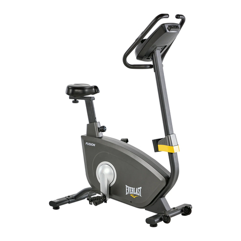
Everlast FUSION EX BIKE User manual