evertz 570NAT-HW-X19 User manual

570NAT-HW-X19
High Density Network Address Translator
User Manual
© Copyright 2020
EVERTZ MICROSYSTEMS LTD.
5292 John Lucas Drive
Burlington, Ontario
Canada L7L 5Z9
Phone: +1 905-335-3700
Sales: sales@evertz.com Fax: +1 905-335-3573
Tech Support: service@evertz.com Fax: +1 905-335-7571
Web Page: http://www.evertz.com
Version 1.0, August 2020
The material contained in this manual consists of information that is the property of Evertz Microsystems and is intended solely for the use of
purchasers of the 570NAT-HW-X19 series product. Evertz Microsystems expressly prohibits the use of this manual for any purpose other than the
operation of the 570NAT-HW-X19 series product. Due to on going research and development, features and specifications in this manual are subject
to change without notice.
All rights reserved. No part of this publication may be reproduced without the express written permission of Evertz Microsystems Ltd. Copies of this
manual can be ordered from your Evertz dealer or from Evertz Microsystems.

This page left intentionally blank

IMPORTANT SAFETY INSTRUCTIONS
The lightning flash with arrowhead symbol within an equilateral triangle is
intended to alert the user to the presence of uninsulated “Dangerous voltage”
within the product’s enclosure that may be of sufficient magnitude to constitute a
risk of electric shock to persons.
The exclamation point within an equilateral triangle is intended to alert the user
to the presence of important operating and maintenance (Servicing) instructions
in the literature accompanying the product.
•Read these instructions
•Keep these instructions.
•Heed all warnings.
•Follow all instructions.
•Do not use this apparatus near water
•Clean only with dry cloth.
•Do not block any ventilation openings. Install in accordance with the manufacturer’s instructions.
•Do not install near any heat sources such as radiators, heat registers, stoves, or other apparatus
(including amplifiers) that produce heat.
•Do not defeat the safety purpose of the polarized or grounding-type plug. A polarized plug has two
blades with one wider than other. A grounding-type plug has two blades and a third grounding prong.
The wide blade or the third prong is provided for your safety. If the provided plug does not fit into your
outlet, consult an electrician for replacement of the obsolete outlet.
•Protect the power cord from being walked on or pinched particularly at plugs, convenience receptacles
and the point where they exit from the apparatus.
•Only use attachments/accessories specified by the manufacturer
•Unplug this apparatus during lightning storms or when unused for long periods of time.
•Refer all servicing to qualified service personnel. Servicing is required when the apparatus has been
damaged in any way, such as power-supply cord or plug is damaged, liquid has been spilled or objects
have fallen into the apparatus, the apparatus has been exposed to rain or moisture, does not operate
normally, or has been dropped.
WARNING
TO REDUCE THE RISK OF FIRE OR ELECTRIC – SHOCK, DO NOT EXPOSE THIS APPA
RATUS TO
RAIN OR MOISTURE
WARNING
DO NOT EXPOSE THIS EQUIPMENT TO DRIPPING OR SPLASHING AND ENSURE THAT NO
OBJECTS FILLED WITH LIQUIDS ARE PLACED ON THE EQUIPMENT
WARNING
TO COMPLETELY DISCONNECT THIS EQUIPMENT FROM THE AC MAINS, DISCONNECT THE
POWER SUPPLY CORD PLUG FROM THE AC RECEPTACLE
WARNING
THE MAINS PLUG OF THE POWER SUPPLY CORD SHALL REMAIN READILY OPERABLE

INFORMATION TO USERS IN EUROPE
NOTE
CISPR 22 CLASS A DIGITAL DEVICE OR PERIPHERAL
This equipment has been tested and found to comply with the limits for a Class A digital device, pursuant
to the European Union EMC directive. These limits are designed to provide reasonable protection against
harmful interference when the equipment is operated in a commercial environment. This equipment
generates, uses, and can radiate radio frequency energy and, if not installed and used in accordance with
the instruction manual, may cause harmful interference to radio communications. Operation of this
equipment in a residential area is likely to cause harmful interference in which case the user will be required
to correct the interference at his own expense.
INFORMATION TO USERS IN THE U.S.A.
NOTE
FCC CLASS A DIGITAL DEVICE OR PERIPHERAL
This equipment has been tested and found to comply with the limits for a Class A digital device, pursuant
to Part 15 of the FCC Rules. These limits are designed to provide reasonable protection against harmful
interference when the equipment is operated in a commercial environment. This equipment generates,
uses, and can radiate radio frequency energy and, if not installed and used in accordance with the
instruction manual, may cause harmful interference to radio communications. Operation of this equipment
in a residential area is likely to cause harmful interference in which case the user will be required to correct
the interference at his own expense.
WARNING
Changes or Modifications not expressly approved by Evertz Microsystems Ltd. could void the user’s
authority to operate the equipment.
Use of unshielded plugs or cables may cause radiation interference. Properly shielded interface cables
with the shield connected to the chassis ground of the device must be used.
EN60065
Safety
EN504192 2005
Waste electrical products should not be
disposed of with household waste.
Contact your Local Authority for recycling
advice
EN55103-1: 1996
Emission
EN55103-2: 1996
Immunity

570NAT-HW-X19
High Density Network Address Translator
Revision 1.0 Page - i
REVISION HISTORY
REVISION
DESCRIPTION
DATE
1.0
First Release
Aug 2020
Information contained in this manual is believed to be accurate and reliable. However, Evertz assumes no responsibility for the use thereof nor
for the rights of third parties, which may be affected in any way by the use thereof. Any representations in this document concerning performance
of Evertz products are for informational use only and are not warranties of future performance, either expressed or implied. The only warranty
offered by Evertz in relation to this product is the Evertz standard limited warranty, stated in the sales contract or order confirmation form.
Although every attempt has been made to accurately describe the features, installation and operation of this product in this manual, no warranty
is granted nor liability assumed in relation to any errors or omissions unless specifically undertaken in the Evertz sales contract or order
confirmation. Information contained in this manual is periodically updated and changes will be incorporated into subsequent editions. If you
encounter an error, please notify Evertz Customer Service department. Evertz reserves the right, without notice or liability, to make changes in
equipment design or specifications.

570NAT-HW-X19
High Density Network Address Translator
Page - ii Revision 1.0
This page left intentionally blank

570NAT-HW-X19
High Density Network Address Translator
Revision 1.0 Page - iii
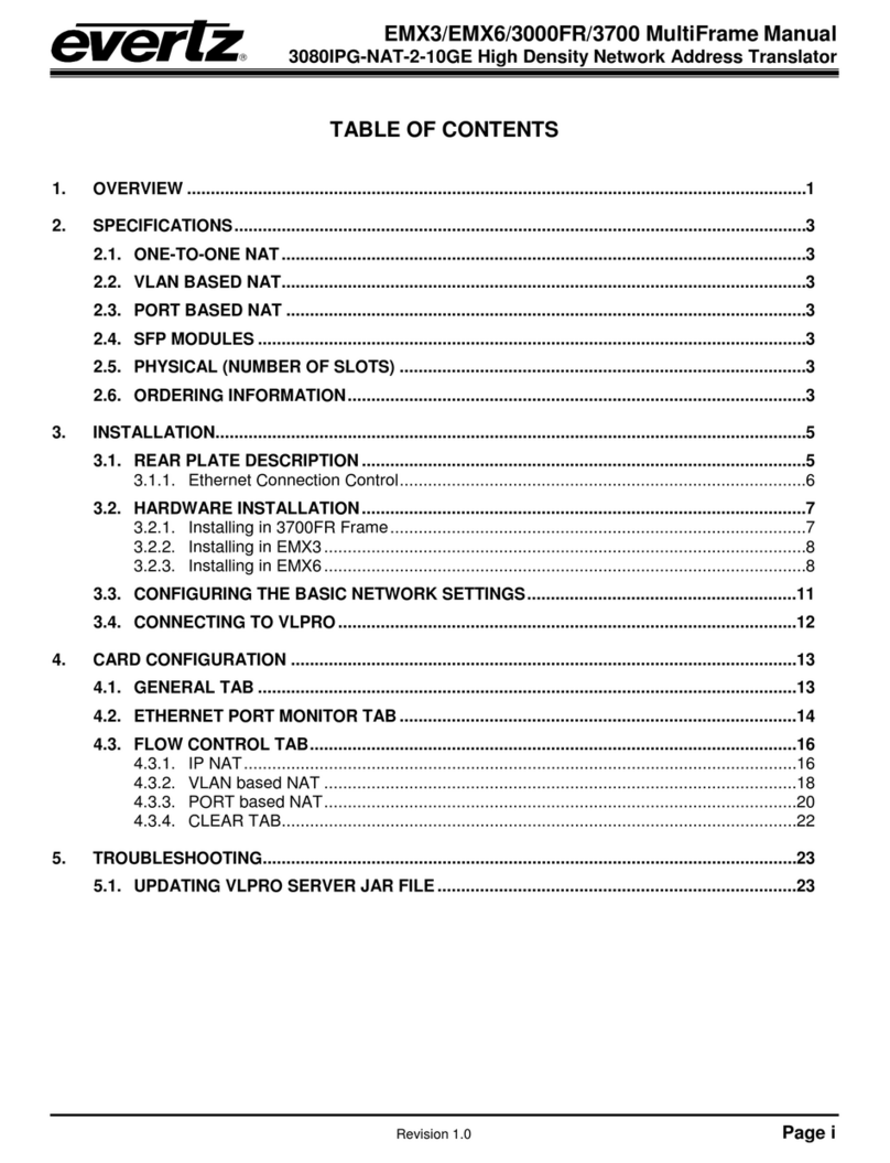
TABLE OF CONTENTS
1. OVERVIEW ...................................................................................................................................1
2. GETTING STARTED .....................................................................................................................5
2.1. REAR PLATE DESCRIPTION ..............................................................................................5
2.2. CARE AND HANDLING OF OPTICAL FIBER......................................................................6
2.3. SETTING DEVICE IP ............................................................................................................7
3. TECHNICAL SPECIFICATIONS ...................................................................................................9
3.1. ONE-TO-ONE NAT ...............................................................................................................9
3.2. MC-IN-MC NAT.....................................................................................................................9
3.3. VLAN-BASED NAT ..............................................................................................................9
3.4. PORT-BASED NAT ..............................................................................................................9
3.5. VIRTUAL INTERFACES .......................................................................................................9
3.6. SFP MODULES ....................................................................................................................9
3.7. ORDERING INFORMATION.................................................................................................9
4. WEB INTERFACE .......................................................................................................................11
4.1. SYSTEM TAB .....................................................................................................................13
4.1.1. Control Port Configuration .......................................................................................13
4.1.2. Processing Cores ....................................................................................................13
4.1.3. Data Port Traffic Monitoring .....................................................................................14
4.1.4. Data Port SFP Monitoring ........................................................................................15
4.1.5. Global Traffic Monitoring..........................................................................................16
4.1.6. Temperature Monitoring...........................................................................................16
4.1.7. TTL ..........................................................................................................................16
4.1.8. Global Data Port SFP Alarm Threshold ...................................................................16
4.1.9. System ....................................................................................................................16
4.2. DATA PORT CONFIGURATIONS ......................................................................................17
4.2.1. Data Ports................................................................................................................17
4.2.2. Port Interfaces .........................................................................................................18
4.3. PORT BASED NAT ............................................................................................................19
4.3.1. LAN to WAN: Encapsulation Header Configuration..................................................20
4.3.2. LAN to WAN: Output Bandwidth Configuration ........................................................21
4.3.3. WAN to LAN: De-Encapsulation Configuration ........................................................22
4.4. VLAN BASED NAT.............................................................................................................23
4.4.1. LAN to WAN: Input Configuration ............................................................................25
4.4.2. LAN to WAN: Encapsulation Header Configuration..................................................25
4.4.3. WAN to LAN: De-Encapsulation Configuration ........................................................25
4.5. IP NAT ................................................................................................................................26
4.5.1. LAN to WAN: Input Flow Configuration ....................................................................27
4.5.2. LAN to WAN: Address Translation Configuration .....................................................27
4.5.3. WAN to LAN: Input Flow Configuration ....................................................................28
4.5.4. WAN to LAN: Address Translation Configuration .....................................................29

570NAT-HW-X19
High Density Network Address Translator
Page - iv Revision 1.0
4.6. MC-IN-MC NAT + IP NAT .................................................................................................. 30
4.6.1. LAN to WAN: Input Flow Configuration ................................................................... 31
4.6.2. LAN to WAN: Address Translation Configuration .................................................... 31
4.6.3. LAN to WAN : Encapsulation Header Configuration ................................................ 32
4.6.4. WAN to LAN: Input Flow Configuration ................................................................... 33
4.7. LINK AGGREGATION ....................................................................................................... 33
4.7.1. Link Aggregation - Grid ........................................................................................... 35
4.7.2. Link Aggregation – Directed .................................................................................... 37
4.7.3. Link Aggregation - Tiled .......................................................................................... 38
4.8. REDUNDANCY .................................................................................................................. 40
4.8.1. Flow Redundancy Between Cores .......................................................................... 40
4.8.2. Flow Redundancy Configuration ............................................................................. 41
4.9. SFP NOTIFY ...................................................................................................................... 41
4.9.1. Notify....................................................................................................................... 41
4.9.2. Port ......................................................................................................................... 41
4.10. NOTIFY CORE ................................................................................................................... 42
4.11. CONFIGURATION MANAGEMENT TAB .......................................................................... 44
5. UPGRADE PROCEDURE........................................................................................................... 45
5.1. WEB INTERFACE - FIRMWARE UPGRADE..................................................................... 45

570NAT-HW-X19
High Density Network Address Translator
Revision 1.0 Page - v
Figures
Figure 1-1: Single NAT Core Block Diagram.................................................................................................... 3
Figure 1-2 : 570NAT-HW-X19 Core Mapping Block Diagram .......................................................................... 3
Figure 1-3: WAN-Side Port Aggregation and Demux (available in all modes)................................................. 4
Figure 2-1: 570NAT-X19-10G Rear Plate ........................................................................................................ 5
Figure 2-2 : WebEASY®- Frame Controller Login ........................................................................................... 7
Figure 2-3 : WebEASY®- Frame Controller -FC Menu .................................................................................. 7
Figure 2-4: WebEASY®- Frame Controller – Side Menu................................................................................. 8
Figure 2-5 : WebEASY®- Frame Controller – Proxy Configuration ................................................................. 8
Figure 4-1: WebEASY® - Login Screen .......................................................................................................... 11
Figure 4-2 : WebEASY®- Main Menu ............................................................................................................ 12
Figure 4-3: WebEASY® - System Tab – Part 1............................................................................................... 13
Figure 4-4: WebEASY® - System Tab – Part 2............................................................................................... 15
Figure 4-5 : WebEASY® - Data Port Configurations...................................................................................... 17
Figure 4-6 : Port Based NAT Mode Block Diagram ....................................................................................... 19
Figure 4-7 : WebEASY® - Port Based NAT ................................................................................................... 20
Figure 4-8 : VLAN Based NAT Mode Block Diagram..................................................................................... 23
Figure 4-9 : WebEASY® - VLAN Based NAT ................................................................................................ 24
Figure 4-10 : WebEASY® - Core Configured as IP NAT (Part 1 – LAN to WAN).......................................... 26
Figure 4-11 : WebEASY® - IP NAT (Part 2 – WAN to LAN) .......................................................................... 28
Figure 4-12 : WebEASY® - MC-in-MC NAT + IP NAT (Part 1)...................................................................... 30
Figure 4-13 : WebEASY® - MC-in-MC NAT + IP NAT (Part 2)...................................................................... 32
Figure 4-14: WebEASY® - Link Aggregation .................................................................................................. 33
Figure 4-15 : WebEASY® - Link Aggregation \ Import Route ........................................................................ 34
Figure 4-16 : WebEASY® - Link Aggregation \ Export Route ......................................................................... 35
Figure 4-17 : WebEASY® - Link Aggregation\Grid View................................................................................. 35
Figure 4-18 : WebEASY® - Link Aggregation\Grid View\Linking in Grid......................................................... 36
Figure 4-19 : WebEASY® - Link Aggregation\Grid View\To Perform in Grid.................................................. 36
Figure 4-20 : WebEASY® - Link Aggregation\Grid View\Removing Links in Grid .......................................... 36
Figure 4-21 : WebEASY® - Link Aggregation\Directed View .......................................................................... 37
Figure 4-22 : WebEASY® - Link Aggregation\Directed View\Linking in Directed ........................................... 37
Figure 4-23 : WebEASY® - Link Aggregation\Directed View\To Perform in Directed..................................... 37
Figure 4-24 : WebEASY® - Link Aggregation\Directed View\Removing Links in Directed ............................. 38
Figure 4-25 : WebEASY® - Link Aggregation\Tiled View................................................................................ 38
Figure 4-26 : WebEASY® - Link Aggregation\Tiled View\Linking in Tiled....................................................... 38
Figure 4-27 : WebEASY® - Link Aggregation\Tiled View\Linking in Tiled....................................................... 39
Figure 4-28 : WebEASY® - Link Aggregation\Directed View\Removing Links in Tiled................................... 39
Figure 4-29 : WebEASY® - Redundancy ........................................................................................................ 40
Figure 4-30: WebEASY® -SFP Notify ............................................................................................................ 41
Figure 4-31 : WebEASY® - Notify Core (1) \ Flow Absent .............................................................................. 42
Figure 4-32 : WebEASY® - Notify Core (2) \ Bandwidth Over Limit................................................................ 43
Figure 4-33: WebEASY® - Configuration Management Tab........................................................................... 44
Figure 5-1: WebEASY® - Upgrade Button on Top Menu Bar ......................................................................... 45
Figure 5-2: WebEASY® - Firmware Upgrade Menu........................................................................................ 45
Figure 5-3: WebEASY® - Firmware Upgrade Menu........................................................................................ 46

570NAT-HW-X19
High Density Network Address Translator
Revision 1.0 Page - vi
This page left intentionally blank

570NAT-HW-X19
High Density Network Address Translator
Revision 1.0 Page - 1
1. OVERVIEW
The 570NAT–X19–10G is a high–density, multi–port, multi–flow hardware Network Address Translation
(NAT) engine with enhanced features including port aggregation, tunneling, packet replication and
bandwidth capping, allowing service providers to seamlessly bridge across networks in multi–tenant
environments.
The 570NAT–X19–10G is organized as 6 WAN–side ports plus 6 LAN–side ports, with a packet
processing core between each WAN–LAN pair. Each processing core can sustain up to 256 data flows,
configurable based on multicasts or VLAN Tags. This gives an exceptional product density of 12x
10GbE ports, with 1536 multicast/VLAN flows — all in the space–efficient Evertz 570 modular hardware
platform.
Multiple processing cores can be configured to aggregate their Tx traffic to a single WAN Port.
Correspondingly, Rx traffic from that WAN port is distributed to its contributing processing cores. WAN–
side port aggregation allows network engineers to achieve functions such as port–based redundancy
using the 570NAT–X19–10G.
The 570NAT–X19–10G is controlled by the industry–leading VistaLINK PRO, and via web interface.
The 12 Ethernet ports support 10GbE and offer full flexibility for LAN and WAN interfacing.
The 570NAT–X19–10G provides four modes of operation:
1. The One–to–One NAT Mode allows unicast/multicast IP streams from one network to be
translated to different unicast/multicast IP addresses, on a flow–by–flow basis, up to 256 unique
flows per processing core. Address translation is available in both directions, while an optional
packet replication feature is provided in the WAN–to–LAN direction.
2. The tunneling (or Encapsulation or MC–in–MC) NAT Mode allows unicast/multicast addresses
from the LAN side to be encapsulated into new multicasts for the WAN network, again, on a
flow–by–flow basis, up to 128 unique settings per processing core. Correspondingly, traffic is
de–encapsulated in the WAN–to–LAN direction.
3. The VLAN Mode allows VLAN–tagged datagrams from the LAN side to seamlessly enter a
WAN after multicast encapsulation, similar to the tunneling NAT mode. In this mode, however, fl
ows are based on VLAN tags, rather than unicasts/multicasts alone. Up to 256 unique flows can
be configured per processing core, with independent encapsulation headers.
4. The port mode allows the user to encapsulate all incoming LAN traffic on a given physical port,
on a port–by–port basis. There is no multicast or VLAN Tag filtering — all traffic on that physical
LAN port is encapsulated out to the WAN and de–encapsulated in the reverse direction. This
mode provides a bandwidth capping feature such that network operators can ensure that links
do not over–subscribe their contribution limits to a WAN.

570NAT-HW-X19
High Density Network Address Translator
Page - 2 Revision 1.0
Features & Benefits
• One–to–one NAT with user configurable Packet Replication
• MC–in–MC NAT for tunneling flows based on multicast addresses
• VLAN based NAT for tunneling flows based on VLAN tag
• Port based NAT for tunneling all traffic (ingress/egress) on per port basis
• Port Aggregation (LAN–to–WAN direction)
• Port Redundancy on both WAN and LAN side (network path failure protection)
• Virtual interfaces for Unicast flows mapping or VLAN ID change
• IGMPv3 with SSM support
• Point–to–point and multi–point signal intra/inter–facility distribution/contribution
• Operates over a Dark fiber, Ethernet, IP, MPLS VPLS, core network
• In–band Management (Management Traffic transport over Multicast)
• Support for FEC Pro MPEG (forward error correction)
• 12x 10GbE (SFP10G–TR13–A)
• Control via 570FC Frame Controller
• Full integration with VistaLINK PRO and MAGNUM
• Standalone Web–based control interface

570NAT-HW-X19
High Density Network Address Translator
Revision 1.0 Page - 3
Figure 1-1: Single NAT Core Block Diagram
Figure 1-2 : 570NAT-HW-X19 Core Mapping Block Diagram

570NAT-HW-X19
High Density Network Address Translator
Page - 4 Revision 1.0
Figure 1-3: WAN-Side Port Aggregation and Demux (available in all modes)

570NAT-HW-X19
High Density Network Address Translator
Revision 1.0 Page - 5
2. GETTING STARTED
2.1. REAR PLATE DESCRIPTION
The 570NAT-HW-X19 comes standard with a companion rear plate. Figure 2-1 provides an illustration of
the 570NAT-HW-X19 rear plate.
Figure 2-1: 570NAT-X19-10G Rear Plate
1GigE or 10GigE Input / Output: There are 12 SFP bi-directional connections used for the 1GE or 10GE
input and output.

570NAT-HW-X19
High Density Network Address Translator
Page - 6 Revision 1.0
2.2. CARE AND HANDLING OF OPTICAL FIBER
Never touch the end face of an optical fiber. Always keep dust caps on optical
fiber connectors when not connected and always remember to properly clean the
optical end face of a connector before making a connection.
The transmission characteristics of the fiber are dependent on the shape of the optical core and therefore
care must be taken to prevent fiber damage due to heavy objects or abrupt fiber bending. Evertz
recommends that the user maintains a minimum bending radius of 5 cm to avoid fiber-bending loss that
will decrease the maximum attainable distance of the fiber cable. The Evertz fiber optic modules come
with cable lockout devices, to prevent the user from damaging the fiber by installing a module into a slot
in the frame that does not have a suitable I/O module.

570NAT-HW-X19
High Density Network Address Translator
Revision 1.0 Page - 7
2.3. SETTING DEVICE IP
The 570NAT-HW-X19 must first be configured through the frame controller. To do so, open a web
browser and type the IP address of the frame controller. You will be presented with the login menu,
Figure 2-2 : WebEASY®- Frame Controller Login
The default login/password combination is admin/admin.
After successfully logging into the frame controller, you will be presented with the FC Menu. If not, you
can access the FC menu by selecting ‘Frame’ from the side menu (highlighted below in Figure 2-3)
Figure 2-3 : WebEASY®- Frame Controller - FC Menu
Once in the FC Menu, take note of which slot the 570NAT-X19 card you are looking to configure.
To set the IP address for this card, proceed by selecting ‘proxy configuration’ in the side menu.

570NAT-HW-X19
High Density Network Address Translator
Page - 8 Revision 1.0
Figure 2-4: WebEASY®- Frame Controller – Side Menu
Once selected, the proxy configuration page will load.
Figure 2-5 : WebEASY®- Frame Controller – Proxy Configuration
Once in the proxy configuration, select the slot number for your 570NAT-X19 card in the frame
controller. Slot selection is displayed just below ‘Network’, here slot #4 has been selected.
Enable proxy mode and set an IP, netmask and gateway for the 570NAT-X19 card.

570NAT-HW-X19
High Density Network Address Translator
Revision 1.0 Page - 9
3. TECHNICAL SPECIFICATIONS
3.1. ONE-TO-ONE NAT
•1536x static mapping
•Packet Replication (WAN-to-LAN direction)
•VLAN ID change
•Ingress traffic filtering based on VLAND ID option
3.2. MC-IN-MC NAT
•1536x Multicast Mapping
3.3. VLAN-BASED NAT
•1536x VLAN ID Mapping
3.4. PORT-BASED NAT
•12x datagram flow mapping (from 12x 10GbE)
3.5. VIRTUAL INTERFACES
•15x interfaces per data port (both WAN and LAN side)
•VLAN ID change (One-to-One NAT mode)
3.6. SFP MODULES
12x SFP Modules
•100GbE optical 850nm, MMF (+SFP10G-TR85-A)
•10GbE optical 1310nm, SMF, 2Km (+SFP10G-TR13S)
•10GbE optical 1310nm, SMF, 10Km (+SFP10G-TR13-A)
•10GbE optical 1550nm, SMF, 40Km (+SFP10G-TR15S)
•10GbE optical 1550nm, SMF, 80Km (+SFP10G-TR15H)
•10GbE optical CWDM (SFP10G-TRCxxH) and DWDM (SFP10G-TRDxxxH)
3.7. ORDERING INFORMATION
570NAT-X19-10G High Density NAT
Enclosures:
570FR 3RU chassis
S570FR 1RU chassis

570NAT-HW-X19
High Density Network Address Translator
Page - 10 Revision 1.0
This page left intentionally blank
Table of contents
Other evertz Electronic Dictionary manuals

evertz
evertz 7700 Series User manual

evertz
evertz MultiFrame EMX3 User manual

evertz
evertz 7700 Series User manual

evertz
evertz 7700 Series User manual

evertz
evertz 7700 Series User manual

evertz
evertz 7700 Series User manual

evertz
evertz 7700 Series User manual

evertz
evertz 7880IPG-NAT Series User manual

evertz
evertz 7700 Series User manual