7700 MultiFrame Manual
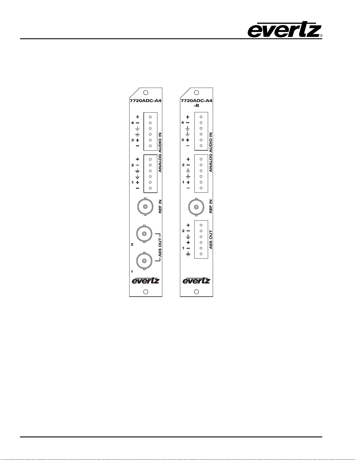
7720ADC-A4-(B) Quad Analog Audio to Dual AES Converter
7720ADC-A4-(B)-8 Revision 1.2
5. CARD EDGE CONTROLS
On the card edge there is a toggle switch and a ten position rotary switch that are used to choose what will
be displayed on the dot matrix display, and to set the gain for each of the analog channels.
5.1. AUDIO LEVELS, HEADROOM, CLIPPING AND THE BAR GRAPHS
This section contains notes to understand how the 7720ADC-A4 relates analog audio levels, digital audio
levels, and the displayed bar graph levels.
Before you can calibrate the audio analog to digital converter, you must know a couple of system issues
specific to your application. What is your analog reference level and how much headroom do you want to
have in the digital audio signal? By adding these two values together, you will get the analog input level
that will just begin to saturate the digital world (This is the highest level that can be represented without
distortion with the digital numbers). This level is called 0dB FS (FS stands for "full scale"). For instance, if
your analog program reference level is 4dBu and you want 20dB of headroom in the "digital world", then
0dB FS will correspond to an analog level of 24dBu. Once the audio input level is calibrated, when you
apply a 4dBu analog signal, the digital level will be –20dB FS.
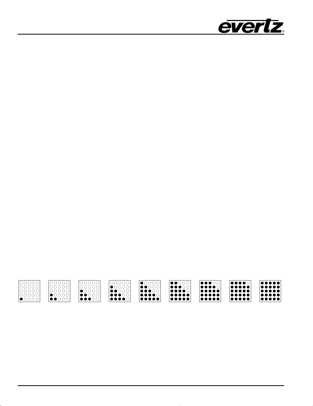
The AES output audio and the bar graphs are all based on the digital quantized signal. The card edge bar
graph display is scaled to 0dB FS.
5.1.1. Input Audio Level Calibration
The analog audio input circuitry has two gain control stages before the audio is digitized. Eight Jumpers
located near the rear of the 7720ADC-A4 module are used to set a coarse gain level. (See Figure 6-1 for
location of jumpers) When the jumpers are not installed, the input range is optimized for when peak audio
levels are up to 24dBu. When the jumpers are installed, best performance is achieved when input peak
levels are below 18dBu.
The toggle switch and rotary switch on the card edge of the 7720ADC-A4 allow independent ±10dB audio
level control of all four channels. To set the gain of one of the audio channels, select the channel number
using the rotary switch. The corresponding channel number will be displayed on the dot matrix display.
Alternately, the current gain setting for the selected channel will be displayed. To increase the gain, push
the toggle switch up (toward the dot matrix display). To decrease the gain, push the toggle switch down.
The gain is adjusted in increments of 0.5 dBu, and will be shown on the dot matrix display. To adjust the
gain for other channels first select the channel using the rotary switch then adjust the level using the
toggle switch. When you are finished setting the gain levels, return the rotary switch to position 0.