evertz 7814UDX-4K Series User manual

7814UDX-4K Series
HD/3G/UHD Up/Down/Cross Converters
User Manual
© Copyright 2016-2018
EVERTZ MICROSYSTEMS LTD.
5292 John Lucas Drive,
Burlington, Ontario,
Canada L7L 5Z9
Phone: +1 905-335-3700
Sales: sales@evertz.com Fax: +1 905-335-3573
Tech Support: service@evertz.com Fax: +1 905-335-7571
Web Page: http://www.evertz.com
Version 1.2, August 2018
The material contained in this manual consists of information that is the property of Evertz Microsystems and is intended solely for the use of
purchasers of the 7814UDX-4K series product. Evertz Microsystems expressly prohibits the use of this manual for any purpose other than the
operation of the 7814UDX-4K series product. Due to on going research and development, features and specifications in this manual are subject
to change without notice.
All rights reserved. No part of this publication may be reproduced without the express written permission of Evertz Microsystems Ltd. Copies of
this manual can be ordered from your Evertz dealer or from Evertz Microsystems.

This page left intentionally blank

IMPORTANT SAFETY INSTRUCTIONS
The lightning flash with arrowhead symbol within an equilateral triangle is
intended to alert the user to the presence of uninsulated “Dangerous voltage”
within the product’s enclosure that may be of sufficient magnitude to constitute
a risk of electric shock to persons.
The exclamation point within an equilateral triangle is intended to alert the user
to the presence of important operating and maintenance (Servicing) instructions
in the literature accompanying the product.
•Read these instructions
•Keep these instructions.
•Heed all warnings.
•Follow all instructions.
•Do not use this apparatus near water
•Clean only with dry cloth.
•Do not block any ventilation openings. Install in accordance with the manufacturer’s instructions.
•Do not install near any heat sources such as radiators, heat registers, stoves, or other apparatus
(including amplifiers) that produce heat.
•Do not defeat the safety purpose of the polarized or grounding-type plug. A polarized plug has two
blades with one wider than other. A grounding-type plug has two blades and a third grounding prong.
The wide blade or the third prong is provided for your safety. If the provided plug does not fit into your
outlet, consult an electrician for replacement of the obsolete outlet.
•Protect the power cord from being walked on or pinched particularly at plugs, convenience
receptacles and the point where they exit from the apparatus.
•Only use attachments/accessories specified by the manufacturer
•Unplug this apparatus during lightning storms or when unused for long periods of time.
•Refer all servicing to qualified service personnel. Servicing is required when the apparatus has been
damaged in any way, such as power-supply cord or plug is damaged, liquid has been spilled or
objects have fallen into the apparatus, the apparatus has been exposed to rain or moisture, does not
operate normally, or has been dropped.
WARNING
TO REDUCE THE RISK OF FIRE OR ELECTRIC –
SHOCK, DO NOT EXPOSE THIS APPARATUS
TO RAIN OR MOISTURE
WARNING
DO NOT EXPOSE THIS EQUIPMENT TO DRIPPING OR SPLASHING AND ENSURE THAT NO
OBJECTS FILLED WITH LIQUIDS ARE PLACED ON THE EQUIPMENT
WARNING
TO COMPLETELY DISCONNECT THIS EQUIPMEN
T FROM THE AC MAINS, DISCONNECT THE
POWER SUPPLY CORD PLUG FROM THE AC RECEPTACLE
WARNING
THE MAINS PLUG OF THE POWER SUPPLY CORD SHALL REMAIN READILY OPERABLE

INFORMATION TO USERS IN EUROPE
NOTE
CISPR 22 CLASS A DIGITAL DEVICE OR PERIPHERAL
This equipment has been tested and found to comply with the limits for a Class A digital device, pursuant
to the European Union EMC directive. These limits are designed to provide reasonable protection
against harmful interference when the equipment is operated in a commercial environment. This
equipment generates, uses, and can radiate radio frequency energy and, if not installed and used in
accordance with the instruction manual, may cause harmful interference to radio communications.
Operation of this equipment in a residential area is likely to cause harmful interference in which case the
user will be required to correct the interference at his own expense.
INFORMATION TO USERS IN THE U.S.A.
NOTE
FCC CLASS A DIGITAL DEVICE OR PERIPHERAL
This equipment has been tested and found to comply with the limits for a Class A digital device, pursuant
to Part 15 of the FCC Rules. These limits are designed to provide reasonable protection against harmful
interference when the equipment is operated in a commercial environment. This equipment generates,
uses, and can radiate radio frequency energy and, if not installed and used in accordance with the
instruction manual, may cause harmful interference to radio communications. Operation of this
equipment in a residential area is likely to cause harmful interference in which case the user will be
required to correct the interference at his own expense.
WARNING
Changes or Modifications not expressly approved by Evertz Microsystems Ltd. could void the user’s
authority to operate the equipment.
Use of unshielded plugs or cables may cause radiation interference. Properly shielded interface cables
with the shield connected to the chassis ground of the device must be used.
EN60065
Safety
EN504192 2005
Waste electrical products should not be
disposed of with household waste.
Contact your Local Authority for recycling
advice
EN55103-1: 1996
Emission
EN55103-2: 1996
Immunity

7814UDX-4K Series
HD/3G/UHD Up/Down/Cross Converters
Revision 1.2 Page - i
TABLE OF CONTENTS
1. OVERVIEW ...................................................................................................................................1
1.1. PRODUCT OPTIONS ...........................................................................................................3
1.2. ENCLOSURES .....................................................................................................................4
2. INSTALLATION.............................................................................................................................5
2.1. INPUT/OUTPUT CONNECTIONS.........................................................................................6
2.2. ETHERNET CONNECTIONS................................................................................................7
2.3. GPIO CONNECTOR.............................................................................................................8
2.4. AES OUTPUTS...................................................................................................................10
2.5. AES INPUTS.......................................................................................................................11
3. SPECIFICATIONS.......................................................................................................................13
3.1. SERIAL DIGITAL VIDEO INPUT ........................................................................................13
3.2. SERIAL DIGITAL VIDEO OUTPUT ....................................................................................13
3.3. REFERENCE VIDEO INPUT...............................................................................................13
3.4. GENERAL PURPOSE INPUTS AND OUTPUTS................................................................13
3.5. AES INPUTS.......................................................................................................................14
3.6. AES OUTPUTS...................................................................................................................14
3.7. ELECTRICAL .....................................................................................................................14
3.8. PHYSICAL..........................................................................................................................14
4. STATUS LEDS............................................................................................................................15
4.1. MODULE STATUS LEDS –AES8 VERSION AND NON –AES8 VERSIONS .....................15
5. WEB INTERFACE.......................................................................................................................17
5.1. VIDEO.................................................................................................................................19
5.1.1. Video Control...........................................................................................................19
5.1.2. Video Monitor ..........................................................................................................21
5.1.3. 4K Inputs .................................................................................................................21
5.1.4. Non-4K Inputs..........................................................................................................22
5.1.5. Audio Inputs.............................................................................................................22
5.2. VIDEO PROC [+VPROC]....................................................................................................23
5.2.1. Gain Levels..............................................................................................................24
5.2.2. DC Offsets...............................................................................................................24
5.2.3. Hue..........................................................................................................................24
5.2.4. Gamma Level ..........................................................................................................24
5.3. HDR [+HDR].......................................................................................................................25
5.3.1. Dynamic Range Selection........................................................................................26

7814UDX-4K Series
HD/3G/UHD Up/Down/Cross Converters
Page - ii Revision 1.2
5.3.2. Advanced HDR Controls..........................................................................................26
5.3.3. Colour Space Selection ...........................................................................................26
5.4. 12G IO (-12G OPTION ONLY)............................................................................................28
5.4.1. 12G Controls ...........................................................................................................28
5.4.2. 12G Input Detected..................................................................................................28
5.4.3. Additional Video Delay.............................................................................................29
5.4.4. Additional Audio Delay.............................................................................................29
5.4.5. Audio Input Presence on Selected 12G Input ..........................................................29
5.5. NOISE REDUCTION...........................................................................................................29
5.6. SCALER.............................................................................................................................30
5.7. REFERENCE......................................................................................................................31
5.7.1. Reference Controls..................................................................................................32
5.7.2. Reference Monitor...................................................................................................33
5.7.3. Auto Reference Fail-over.........................................................................................33
5.8. AUDIO ................................................................................................................................34
5.9. AUDIO INPUT CORRECTION [+APROC]..........................................................................36
5.10. AUDIO MIXER....................................................................................................................37
5.11. CLOSED CAPTIONING......................................................................................................40
5.11.1. Closed Captioning Controls.....................................................................................40
5.11.2. Closed Captioning Status ........................................................................................41
5.12. ANC PASS THRU...............................................................................................................41
5.12.1. Mapped ANC Pass Thru Controls............................................................................42
5.12.2. Direct ANC Pass Thru Control.................................................................................44
5.13. GPIO...................................................................................................................................45
5.14. IP ........................................................................................................................................45
5.14.1. Control IP Configuration...........................................................................................45
5.15. PRESETS ...........................................................................................................................46
5.15.1. Preset Control..........................................................................................................46
5.15.2. User Presets............................................................................................................47
5.16. VERSION INFO ..................................................................................................................48
5.17. PRODUCT STRING............................................................................................................49
6. JUMPERS ...................................................................................................................................51
6.1. MONITORING LOCAL FAULTS BY THE GLOBAL FRAME STATUS ..............................52
6.2. 7814UDX-4K SERIES “SLOT BLOCKER” ........................................................................52
7. UPGRADE PROCEDURES.........................................................................................................53
7.1. FIRMWARE UPGRADE......................................................................................................53

7814UDX-4K Series
HD/3G/UHD Up/Down/Cross Converters
Revision 1.2 Page - iii
Figures
Figure 1-1 : 7814UDX-4K Series Block Diagram............................................................................3
Figure 2-1 : 7814UDX-AES8-4K and 7814UDX-AES8-4K-12G Rear Plates ..................................5
Figure 2-2 : GPI Input Circuitry ......................................................................................................9
Figure 2-3 : GPO Output Circuitry..................................................................................................9
Figure 4-1 : Status LEDs..............................................................................................................15
Figure 5-1 : WebEASY® - Login Menu..........................................................................................17
Figure 5-2 : WebEASY®- 7814-AES8-4K-12G Menu...................................................................18
Figure 5-3 : WebEASY® - Video Panel.........................................................................................19
Figure 5-4 : WebEASY® - Video Proc Panel.................................................................................23
Figure 5-5 : WebEASY® - HDR.....................................................................................................25
Figure 5-6 : HDR to SDR Conversion Diagram............................................................................27
Figure 5-7 : HDR to SDR Conversion Diagram............................................................................27
Figure 5-8 : WebEASY® - 12G IO.................................................................................................28
Figure 5-9 : WebEASY® - Noise Reduction Panel ........................................................................29
Figure 5-10 : WebEASY® - Scaler Panel......................................................................................30
Figure 5-11 : WebEASY® - Reference Panel................................................................................31
Figure 5-12 : WebEASY® - Audio Panel.......................................................................................34
Figure 5-13 : WebEASY® - Audio Input Correction Panel.............................................................36
Figure 5-14 : Audio Mixer Diagram for each Audio Channel.........................................................37
Figure 5-15 : WebEASY® - Audio Mixer Panel..............................................................................38
Figure 5-16 : WebEASY® - Closed Captioning Panel ...................................................................40
Figure 5-17 : WebEASY® - ANC Pass Thru Panel........................................................................42
Figure 5-18 : WebEASY® - GPIO Panel .......................................................................................45
Figure 5-19 : WebEASY® - IP Panel.............................................................................................45
Figure 5-20 : WebEASY® - Presets Panel ....................................................................................46
Figure 5-21 : WebEASY® - Version Info Panel .............................................................................48
Figure 5-22 : WebEASY® - Product String Panel..........................................................................49
Figure 6-1 : Location of Jumpers – Top View Main Module..........................................................51
Figure 6-2 : Location of Jumpers – Bottom View Main Module.....................................................51
Figure 6-3 : Slot Blocker ..............................................................................................................52
Figure 7-1 : WebEASY® - Upgrade Button on Top Menu Bar .......................................................53
Figure 7-2 : WebEASY® - Firmware Upgrade Menu....................................................................53
Figure 7-3 : WebEASY® - Firmware Upgrade Menu.....................................................................54
Tables
Table 1-1 : Differences Between 7814UDX-4K Series Converters (Ordering Options)..................2
Table 1-2 : Description of product options for 7814UDX-4K Series Converters.............................3
Table 2-1 : Colour Code Wiring for the Current RJ 45 Standards...................................................7
Table 2-2 : GPIO Connector Pin out ..............................................................................................8
Table 2-4 : AES Output Audio Connector Pin out.........................................................................10
Table 2-5 : AES Input Audio Connector Pin out ...........................................................................11
Table 5-1 : Presets – Input Video Standard Preset Triggers ........................................................48
7814UDX-4K Series
HD/3G/UHD Up/Down/Cross Converters
Page - iv Revision 1.2
This page left intentionally blank

7814UDX-4K Series
HD/3G/UHD Up/Down/Cross Converters
Revision 1.2 Page - v
REVISION HISTORY
REVISION DESCRIPTION DATE
1.0
First Release
June 2016
1.1
Error Fixing
Dec 2016
1.2
Added HDR and 12G Options/Updates Throughout
Aug 2018
Information contained in this manual is believed to be accurate and reliable. However, Evertz assumes no responsibility for the use thereof nor for
the rights of third parties, which may be affected in any way by the use thereof. Any representations in this document concerning performance of
Evertz products are for informational use only and are not warranties of future performance, either expressed or implied. The only warranty offered
by Evertz in relation to this product is the Evertz standard limited warranty, stated in the sales contract or order confirmation form.
Although every attempt has been made to accurately describe the features, installation and operation of this product in this manual, no warranty is
granted nor liability assumed in relation to any errors or omissions unless specifically undertaken in the Evertz sales contract or order confirmation.
Information contained in this manual is periodically updated and changes will be incorporated into subsequent editions. If you encounter an error,
please notify Evertz Customer Service department. Evertz reserves the right, without notice or liability, to make changes in equipment design or
specifications.

7814UDX-4K Series
HD/3G/UHD Up/Down/Cross Converters
Page - vi Revision 1.2
This page left intentionally blank

7814UDX-4K Series
HD/3G/UHD Up/Down/Cross Converters
Revision 1.2 Page - 1
1. OVERVIEW
Addressing the needs of content procedures and distributors to be able to supply UHD, 3G and HD
content in parallel, the 7814UDX-4K, 7814UC-4K, 7814XC-4K and 7814HDC-4K are a series of broadcast
quality up/down converters that convert between common HD/SMPTE 292M and 3G/SMPTE 424M video
signals and UHD. Models are available to support upconversion, downconversion, crossconversion or a
combination:
7814UC-4K : 3G/HD to UHD upconverter
7814HDC-4K : UHD to 3G/HD downconverter
7814UDX-4K : UHD to/from 3G/HD up and downconverter
7814XC-4K : UHD cross-converter (also supports 2SI to Quadrant based UHD conversions)
The 7814UDX/UC/XC/HDC-4K Series supports broadcast quality video conversion. Advanced motion
adaptive spatial-temporal (3D) noise reduction and next generation de-interlacing techniques ensure
superior resolution and artifact reduction, generating the highest quality video suitable for broadcast and
other professional media applications. Optionally available video processing features (+VPROC option)
include full broadcast quality color correction and detail enhancement processors along with RGB based
color legalization.
The 7814UDX-4K series products are HDR capable (with +VPROC and +HDR options) and can
up/down/cross convert SDR and a range of HDR formats, including SMPTE ST 2084 (PQ), HLG and
S-Log3. It also performs all colour space conversion including BT.709, BT.2020 and S.Gamut3. Rather
than using fixed LUTs, the Evertz HDR conversion uses high-precision 32 bit mathematical modelling to
allow for very low-latency, high accuracy transforms while allowing on-the-fly changes to colour correction
or HDR transfer function parameters.
The 7814UDX-4K Series transparently supports 16 channels of embedded audio with audio delay
automatically matching video delay. Optional audio processing features (+APROC option) include audio
channel shuffling, gain, inversion and mono-mixing. With “-AES8” variants, 8 discrete AES inputs and 8
discrete AES outputs are provided, allowing for discrete AES input and output. Full audio routing capability
allows outgoing embedded and discrete AES audio (-AES8 versions) to be sourced from any combination
of embedded audio, discrete AES inputs (-AES8 versions) or processed audio.
The -12G option adds support for SMPTE ST 2082 and enables up to 2x 12G SFPs (ordered separately)
to be added to allow transport over a single coax or Fiber. The -12G-HDBNC-R option includes an
HDBNC module that supports coaxial 12G-SDI signals.
These modules are SNMP capable for remote monitoring, control and configuration capabilities using
WebEASY®, VistaLINK® PRO, CP-2116E or CP-2232E Control Panels. SNMP control is available when
modules are used with the 3RU 7800FR series or 1RU 7801 frames and a 7700/7800/7801FC Frame
Controller module is installed. Each card occupies two slots in the frame and the card does not support
direct SNMP configuration.

7814UDX-4K Series
HD/3G/UHD Up/Down/Cross Converters
Page - 2 Revision 1.2
HD to
HD
(SF)
HD to
HD
(DF)
HD
to
3G
HD to
4K
3G to
HD
3G to
3G
(SF)
3G to
3G
(DF)
3G to
4K
4K to
HD
4K to
3G
4K to
4K
(SF)
4K to
4K
(DF)
7814UDX-4K ●●●●●●●●●●●●
7814HDC-4K ●OB OB OB ●●OB OB ●●●OB
7814UC-4K ●OB ●●OB ●OB ●OB OB ●OB
7814XC-4K ●●OB OB OB ●●OB OB OB ●●
● Normal Operation
OB Outputs Black
SF Same format (1080i to 1080i)
DF Difference format (720p to 1080i or 1080i to 720p)
Table 1-1 : Differences Between 7814UDX-4K Series Converters (Ordering Options)
This manual will serve to cover the 7814UDX-4K, the 7814UC-4K, the 7814-XC and the 7814HDC-4K
base products as well as the –AES8 versions.
Features & Benefits
•Broadcast quality up/downconversion between common HD/SMPTE 292M and 3G/SMPTE 424M
video signals to/from UHD.
•Integrated frame synchronizers (quad input frame synchronizers on 7814UDX-4K and 7814HDC-
4K to time quad-lane SDI inputs)
•Support for card reference connection and two sources of 7800FR frame reference (software
selectable from the three sources)
•Advanced 3D noise reduction and next generation de-interlacing technologies ensure the highest
quality video without compromise for broadcast and professional media applications
•Broadcast quality color corrector and detail enhancement engines optional (+VPROC option)
•16 channel embedded audio support
•Audio delay automatically tracks video delay
•Full audio proc and channel swapping plus 5.1 surround sound to stereo (Lt/Rt and Lo/Ro) down-
mixing provided with +APROC option
•Supports 8 external AES inputs and 8 AES outputs (-AES8 versions only)
•SNMP capable for remote monitoring, control and configuration capabilities using WebEASY®,
VistaLINK® PRO, CP-2116E or CP-2232E Control panels
•VistaLINK® is available when modules are used with the 3RU 7800FR frame and a 7700FC
VistaLINK® Frame Controller module in slot 1 of the frame

7814UDX-4K Series
HD/3G/UHD Up/Down/Cross Converters
Revision 1.2 Page - 3
AES Rx
Audio Processing & Aud io
Delay
Frame
Sy nc
EQ
&
SP
Adva nced Noise
Reduction and
De-interlacer
Up/Do wn/Cross
Conversion and
Aspect Ratio Convert
Output Processing
Enh ance ment Gamma
Proc +Legalize
(+VPROC Option
Only)
HDR Processing
(+HDR Option Only)
S im pl e P /S
AES Tx
Cable
Driver
Cable
Driver
Cable
Driver
Module Control
Status
Indi cator s
GPIO Interfac e
Reference
Timing
Generator
10/100
Ethernet
EQ
&
SP Frame
Sy nc
8 AES
Outputs
VistaLINK®
control
PG M OUT A1
GPI/O
PGM A IN
*3G/HD
Reference
Input
(Genlock)
AudioPresent
-AES8 Only -AES8 Only
8 AES
Inpu ts
PGM B IN
*3G/HD
FRAME
REF
Video
Pr es en t Mod ule
Status Reference
Pr es en t Fault
Frame
Sy nc
Frame
Sy nc
EQ
&
SP
PGM B IN
*3G/HD
EQ
&
SP
PGM B IN
*3G/HD
PG M OUT A2
Cable
Driver
PG M OUT B1
PG M OUT B2
PG M OUT C1
PG M OUT C2
PG M OUT D1
PG M OUT D2
Cable
Driver
Cable
Driver
Cable
Driver
Demux
Cable
Driver
Cable
Driver
-12G Option Only
-12G Option Only
12G SDI IN 12GSDI IN
Figure 1-1 : 7814UDX-4K Series Block Diagram
1.1. PRODUCT OPTIONS
This manual covers all variations and ordering options for the 7814UDX-4K Series platform. The majority
of card controls are common across all products variations (7814UDX-4K, 7814UC-4K, 7814XC-4K and
7814HDC-4K) and ordering options. A small number of items change depending on the product variation
and ordering option. The following chart provides a list of available product variations/ordering options and
outlines what module control changes based on each.
Options
Description
-AES8 Adds 8 AES inputs and outputs to the audio mixing controls.
+VPROC Video proc/color correction support including RGB, YCbCr.
+APROC
Audio processing support including 5.1 to stereo down-mixing (LoRo to LtRt), global audio
delay, audio channel shuffling, gain, inversion and mono-mix capabilities on 16 channels of
embedded audio (Note: included as standard on –AES8 versions, optional on non-AES8
versions)
+HDR Translates a range of HDR formats, including SMPTE2084 (PQ), HLG and S-Log3.
Performs all colour space conversion including BT.709, BT.2020 and S.gamut3.
Uses high-precision mathematical modelling rather than fixed LUTs.
Table 1-2 : Description of product options for 7814UDX-4K Series Converters
The following can assist in the customization and ordering options:
7814 {UDX/UC/XC/HDC} [-AES8] -4k [+APROC] [+VPROC] [HDR]
Explanation of notation: / = or, { } = mandatory, [ ] = optional

7814UDX-4K Series
HD/3G/UHD Up/Down/Cross Converters
Page - 4 Revision 1.2
1.2. ENCLOSURES
7800FR 3RU Multiframe which holds up to 15 single slot modules
7800FR-QT 3RU Multiframe which holds up to 15 single slot modules, low noise
7801FR 1RU Multiframe which holds up to 4 single slot modules or two dual slot modules

7814UDX-4K Series
HD/3G/UHD Up/Down/Cross Converters
Revision 1.2 Page - 5
2. INSTALLATION
All 7814UDX-4K series modules come with a companion rear plate and occupy two slots in the 7800FR
frame or three slots in the 7700FR-C. If a 7814UDX-4K series module is installed in a 7700FR-C without
the “slot blocker” installed, the card will not power-up and will show RED on its main status LED. For
information on mounting the rear plate and inserting the module into the frame see section 3 of the
7700FR manual. Refer to section 6.2 of this manual for more information on the 7814UDX-4K series slot
blocker. Refer to Figure 2-1 for 7814UDX-4K series rear plate layouts.
NOTE:For proper operation in the 7700FR-C, the on-board “slot blocker” must be installed in
order for the card to power-up.
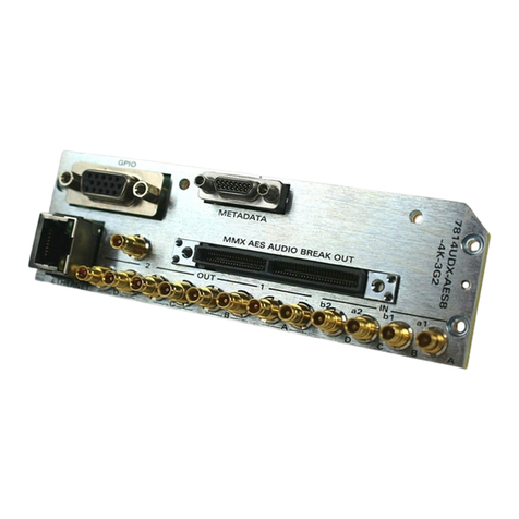
Figure 2-1 : 7814UDX-AES8-4K and 7814UDX-AES8-4K-12G Rear Plates

7814UDX-4K Series
HD/3G/UHD Up/Down/Cross Converters
Page - 6 Revision 1.2
2.1. INPUT/OUTPUT CONNECTIONS
PGM IN A/B/C/D: Accepts a 10-bit serial digital video signal. All inputs are compatible with SMPTE
292M, SMPTE 372M and SMPTE 425M standards. The module can be set to
receive a specific video standard or set to automatically detect the supplied input
video standard.
Note: Non-4K inputs must be plugged in to PGM IN A.
PGM OUTPUT A1/A2/B1/B2/C1/C2/D1/D2:
These DIN connectors are used to output video as serial component video. All outputs are compatible with
SMPTE 292M, SMPTE 259M or SMPTE 372M standard.
REF IN: This DIN is for connecting a bi-level or tri-level reference. The Reference format is auto-
detected by the module. Output video can be timed with respect to the supplied
reference using the H Phase Offset and V Phase Offset module controls. When no
reference is provided, the output video is timed with respect to the input video.
Reference may also be supplied via the 7700FR-QT, 7801FR and 7800FR FRAME
REFERENCE inputs. User Control is used to select either the card’s external reference
or the FRAME REFERENCE inputs.
The 7814UDX-4K series conversion modules accept standard reference signals including bi-phase (525i59
or 625i50) and tri-level sync signals (1080i59 or 1080i50).

7814UDX-4K Series
HD/3G/UHD Up/Down/Cross Converters
Revision 1.2 Page - 7
2.2. ETHERNET CONNECTIONS
All 7814UDX-4K series modules are designed to use either 10Base-T (10 Mbps) or 100Base-TX (100
Mbps) also known as Fast Ethernet, twisted pair Ethernet cabling systems. When connecting for 10Base-
T systems, category 3, 4, or 5 UTP cable as well as EIA/TIA – 568-100ΩSTP cable may be used. When
connecting for 100Base-TX systems, category 5 UTP cable is required. Make the network connection by
plugging one end of a “straight through” cable into the RJ-45 receptacle of 7814UDX-4K modules and the
other end into a port of the supporting hub. If you are connecting the 7814UDX-4K series modules directly
to an Ethernet port on a computer, you will have to use a “crossover” cable.
Straight-through RJ-45 cables can be purchased or can be constructed using the pin out information in
Table 2-2. A color code-wiring table is provided in Table 2-1 for the current RJ-45 standards (AT&T 258A
or EIA/TIA 258B color coding shown). Also, refer to the notes following the table for additional wiring guide
information.
Pin
1
Pin # Signal EIA/TIA 568A
AT&T 258A or
EIA/TIA 568B
10BaseT
or 100BaseT
1 Transmit + White/Green White/Orange X
2 Transmit – Green/White or White
Orange/White or
Orange
X
3 Receive + White/Orange White/Green X
4 N/A Blue/White or Blue Blue/White or Blue
Not used
(required)
5 N/A White/Blue White/Blue
Not used
(required)
6 Receive – Orange/White or Orange Green/White or Green X
7 N/A White/Brown White/Brown
Not used
(required)
8 N/A Brown/White or Brown Brown/White or Brown
Not used
(required)
Table 2-1 : Colour Code Wiring for the Current RJ 45 Standards
Note the following cabling information for this wiring guide:
•Only two pairs of wires are used in the 8-pin RJ 45 connector to carry Ethernet signals.
•Even though pins 4, 5, 7 and 8 are not used, it is mandatory that they be present in the cable.
•10BaseT and 100BaseT use the same pins; a crossover cable made for one will work with the
other.
•Pairs may be solid colors and not have a stripe.
•Category 5 cables must use Category 5 rated connectors.
The maximum cable run between the 7814UDX-4K series modules and the supporting hub is
300 ft (90 m).

7814UDX-4K Series
HD/3G/UHD Up/Down/Cross Converters
Page - 8 Revision 1.2
2.3. GPIO CONNECTOR
There are 8 General Purpose Inputs/Outputs (GPIOs) on the 7814UDX-4K series modules. Each GPIO
may be configured to be an input or configured to be an output. These GPIOs are interfaced using a
15-pin DB connector and an associated breakout cable (cable part # WPAES8-DINM-9W-6F).
NOTE: The GPIO breakout cable is not included with the module when purchased. Table 2-2 shows the
Pin-out of this connector as follows:
DB-15 Pin
Name
Description
1
GPIO1
General Purpose Input / Output #1
2
LTC OUT
External LTC out
3
GPIO2
General Purpose Input / Output #2
4
GPIO4
General Purpose Input / Output #4
5
6 HZ IN
6 Hz In
6
LTC IN 1
External LTC In 1
7
SERIAL-A TX-
Serial Port A Transmit Negative
8
GPIO3
General Purpose Input / Output #3
9
GPIO8
General Purpose Input / Output #8
10
SERIAL-A RX+
Serial Port A Receive Positive
11
GPIO5
General Purpose Input / Output #5
12
GPIO6
General Purpose Input / Output #6
13
SERIAL-A TX+
Serial Port A Transmit Positive
14
GPIO7
General Purpose Input / Output #7
15
SERIAL-A RX-
Serial Port A Receive Negative
Shell
GND
Ground
Table 2-2 : GPIO Connector Pin out
NOTE: LTC, 6 Hz and Metadata inputs and outputs are not supported in the current Firmware
version (2.24 B 324).

7814UDX-4K Series
HD/3G/UHD Up/Down/Cross Converters
Revision 1.2 Page - 9
When a particular GPIO is configured to be a GPI, the following interface shall apply (Figure 2-2):
GPI
GND
GPI
Command
to
internal
circuit
3.6 K
+ 5
VDC
Figure 2-2 : GPI Input Circuitry
When a particular GPIO is configured to be a GPO, the interface shown below shall apply. The GPO is
active low with internal pull up (10k Ohm) resistors to +5V. When the output goes low, it is able to sink up
to 10mA. When high, the signal will go high (+5V). Do not draw more than 100µA from the output.
Figure 2-3 shows the circuit for the general-purpose output.
From Internal
Circuit
+ 5 Volts
GND
GPO
10 ohm
10 K
Figure 2-3 : GPO Output Circuitry

7814UDX-4K Series
HD/3G/UHD Up/Down/Cross Converters
Page - 10 Revision 1.2
2.4. AES OUTPUTS
The –AES8 versions of 7814UDX-4K series modules support 8x AES outputs per path and are interfaced
using a Multi-path Module Conversion breakout (MMX breakout) connector and a breakout cable. The part
number for the cable is #WP/1M/MMX-AUDIO. One MMX audio breakout cable is included when
the –AES8 option is ordered. The pin-out of the MMX connector is shown in Table 2-4.
Pin 1 Pin 2
Female
MMX Audio
Breakout
PIN #
Name
Description
1
GND
Ground
2
GND
Ground
3
AES OUT1 1
AES Output 1 Path 1 – Unbalanced
4
AES OUT1 2
AES Output 2 Path 1 – Unbalanced
7
GND
Ground
8
GND
Ground
9
AES OUT1 3
AES Output 3 Path 1 – Unbalanced
10
AES OUT1 4
AES Output 4 Path 1 – Unbalanced
13
GND
Ground
14
GND
Ground
15
AES OUT1 5
AES Output 5 Path 1 – Unbalanced
16
AES OUT1 6
AES Output 6 Path 1 – Unbalanced
19
GND
Ground
20
GND
Ground
21
AES OUT1 7
AES Output 7 Path 1 – Unbalanced
22
AES OUT1 8
AES Output 8 Path 1 – Unbalanced
25
GND
Ground
26
GND
Ground
27
Not Connected
28
Not Connected
31
GND
Ground
32
GND
Ground
33
Not Connected
34
Not Connected
37
GND
Ground
38
GND
Ground
39
Not Connected
40
Not Connected
43
GND
Ground
44
GND
Ground
45
Not Connected
46
Not Connected
Table 2-4 : AES Output Audio Connector Pin out
Table of contents
Other evertz Media Converter manuals

evertz
evertz 7700 Series User manual

evertz
evertz 2405EO-HD User manual

evertz
evertz 7700 Series User manual

evertz
evertz 7700 Series User manual

evertz
evertz 2430GDAC User manual

evertz
evertz 7700 MultiFrame User manual

evertz
evertz 7705OE-3 User manual

evertz
evertz 7700 Series User manual

evertz
evertz 7721AE4-HD User manual

evertz
evertz 2432TX-2 User manual

evertz
evertz 7735CEM User manual

evertz
evertz 3080UEP Series User manual

evertz
evertz 8074 User manual

evertz
evertz 7800 User manual

evertz
evertz HD2014 User manual

evertz
evertz 5010 SIE User manual

evertz
evertz 7700 Series User manual

evertz
evertz 7700 MultiFrame User manual

evertz
evertz 5782DEC User manual

evertz
evertz 7707EO-3G User manual