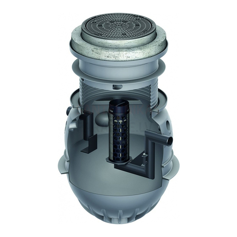
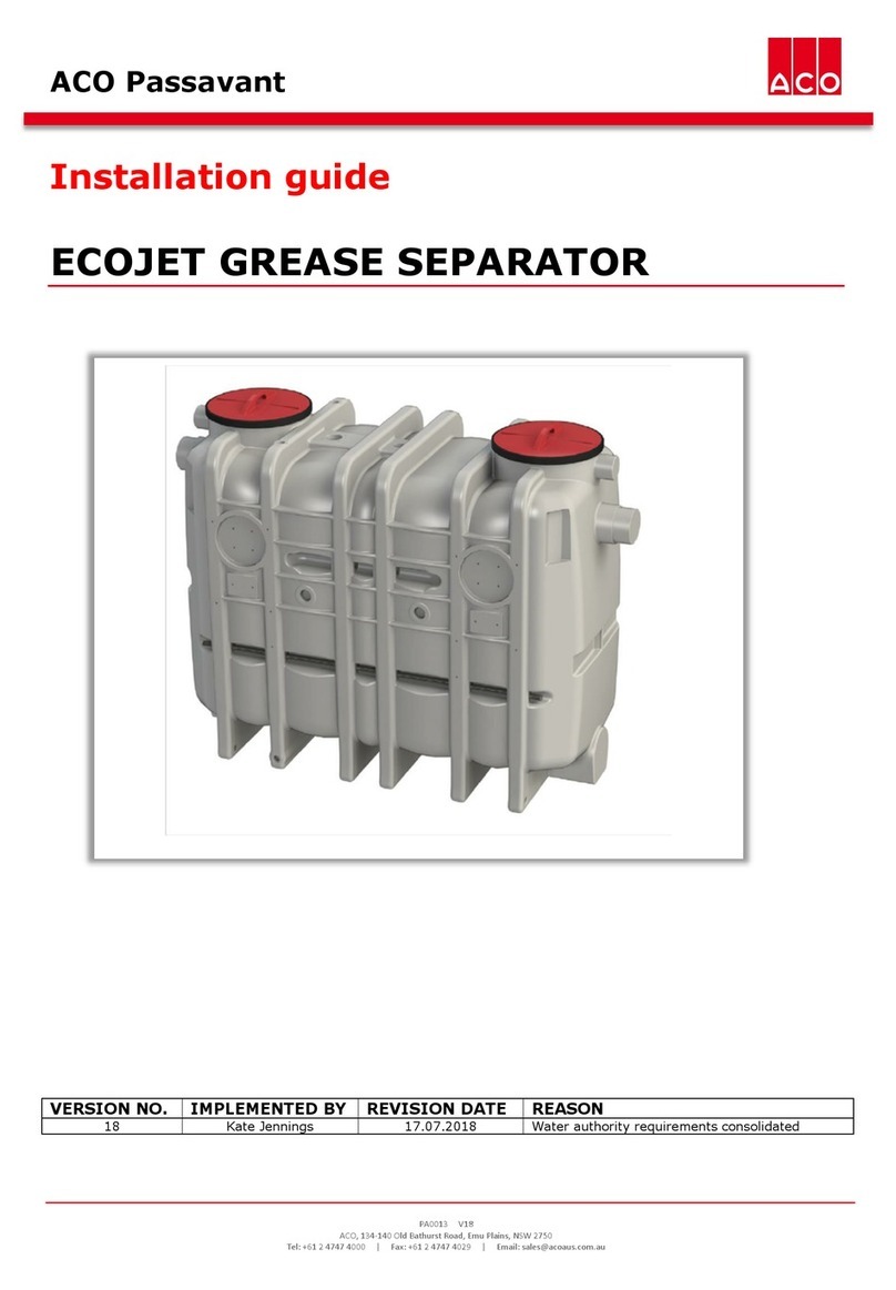
ACO Lipumax-P User manual

PA0017 v2
ACO, 134-140 Old Bathurst Road, Emu Plains, NSW 2750
ACO Passavant
Installation guide
LIPUMAX GREASE TRAP
VERSION NO.
IMPLEMENTED BY
REVISION DATE
REASON
1
Kate Jennings
17 July 2018
Combination of Lipumax-P and Lipumax-G
2
Kate Jennings
9 July 2019
Single o-ring riser and introduction of deeper riser
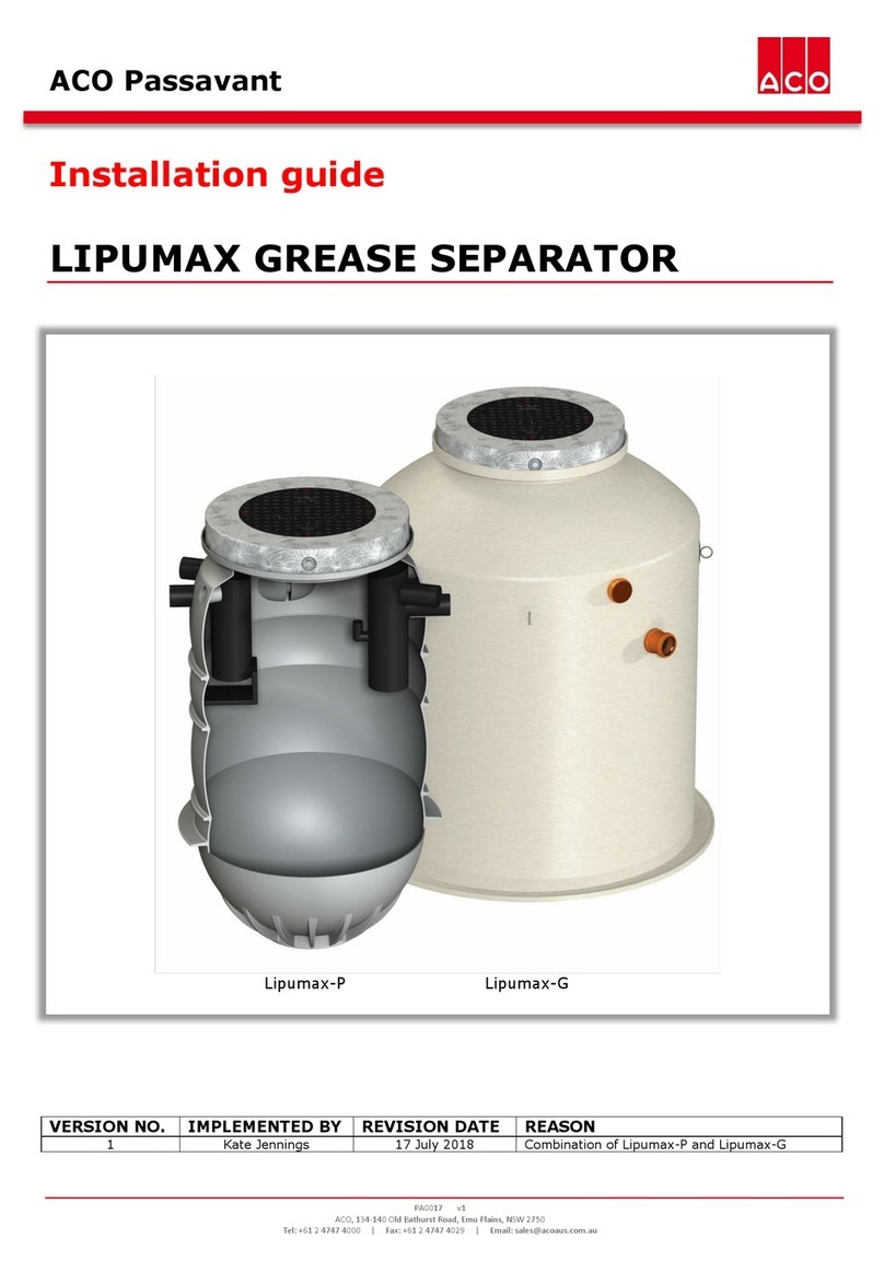
Lipumax-P Lipumax-G

LIPUMAX GREASE TRAP - Installation guide | Kate Jennings
2
Contents
1GENERAL..............................................................................................................................................3
2SAFETY CONSIDERATIONS .........................................................................................................3
3SIZING ..................................................................................................................................................4
4INSTALLATION .................................................................................................................................5
5WATER AUTHORITY APPROVALS...........................................................................................12
6CONTACT INFORMATION...........................................................................................................13

LIPUMAX GREASE TRAP - Installation guide | Kate Jennings
3
1GENERAL
The ACO Passavant Lipumax grease trap is designed for below ground installation only.
Lipumax grease traps are designed to remove waste Fats, Oils and Grease (FOG) from
commercial tradewaste from applications such as commercial. They are not anticipated
for use in residential applications.
When discharging tradewaste into the public sewer system, local water authority
requirements must be adhered to.
2SAFETY CONSIDERATIONS
All work in installing and maintaining this grease trap shall comply with requirements of
the relevant authorities.
2.1 Site handling
Inspect the Lipumax upon delivery and prior to installation, check for damage that may
have occurred during transportation or at the job site prior to installation.
Grease traps can be large. To avoid damage to the grease trap, ensure that correct
equipment (e.g. forklift, crane or sling ropes) is available for proper unloading and
manoeuvring on site. Use lifting provisions (shown below).
Note: 2000L and above traps may require a 3 tonne excavator to dig the required depth.
2.2 Workplace Health and Safety (WHS)
•All safety instruction labels must be replaced if they become detached or illegible
•Installed devices (e.g. baffles, inlets, outlets etc.) are not load bearing. They must
not be used as steps, footholds or resting places for cleaning equipment etc.
•Grease traps should be not be installed where a danger to health is possible from
the grease separator leaking, blocking or surcharging.
•Ensure the angle of excavation is suitable for the soil type.

LIPUMAX GREASE TRAP - Installation guide | Kate Jennings
4
3SIZING

LIPUMAX GREASE TRAP - Installation guide | Kate Jennings
5
Each Lipumax trap requires a gas and water tight access cover (complaint to AS 3996) to
close the system and offer access for maintenance purposes. A range of Class B and
Class D covers and assemblies are available.
4INSTALLATION
The Lipumax grease trap must be installed in compliance with local water authority
regulations (see section 5), Safe Work Australia, national plumbing standards and all
other codes of practice. Prior to installation, ensure that the local water authority
approves each installation.
The cover assembly selection will determine the overall installation depth. When
installed, the tops of the cover and collar assembly should be flush with the finished
surface level.

LIPUMAX GREASE TRAP - Installation guide | Kate Jennings
6
4.1 Installation steps
1. Check all dimensions carefully before installation. Excavate to the required depth,
allowing for the trap depth (as outlined in section 3) and an additional 100mm,
and at least 300mm on either side. The width of excavation should be sufficient
for the compactor to access.
2. Place stabilised bedding sand or concrete in the base of the hole and compact so
it is level and free of rocks or other unsuitable materials.
3. Connect the required lifting apparatus to the grease trap. Lower the grease trap
into the excavation and align the inlet, outlet and ventilation pipes to required
positions. Place 200mm stabilised bedding sand or concrete around the trap and
compact. The grease trap should be filled with water and backfilled with
compacted sand and gravel or soil in 300mm sections. Ensure backfill is free of
rocks, or other unsuitable materials.
4. Connect inlet, outlet, I.O/TWSP and vent pipes. Two vent connections are
available to suit on-site requirements.
5. Install the cover and collar assembly selected.
4.2 Connecting pipes
Lipumax grease traps can be used in conjunction with a number of different pipe
materials. Connecting pipes and pipe materials should be installed in accordance with
AS/NZS 3500 and local plumbing codes.
Note: Check manufacturers’ approvals for use in ground slab applications, prior to use.
I.O
I.O / TWSP
Vent
*I.O –Inspection opening
* TWSP –Trade Waste Sampling Point
Outlet
Ventilation connection

LIPUMAX GREASE TRAP - Installation guide | Kate Jennings
8
4.3 Installation drawings
Following are some typical installation details. For additional installation details and
downloadable installation details, visit www.acopassavant.com.au.
Class B (AS 3996) with access cover and reinforced concrete collar

LIPUMAX GREASE TRAP - Installation guide | Kate Jennings
9
Class D (AS 3996) with concrete collar, load distribution plate and riser tube
Prior to installation the rebate must be cut to off the top of the riser tube (along the
dotted line shown below) using the groove provided, as per the diagrams below.
1. Prepare riser by cutting it to
the required height.
2. Lubricate the riser tube,
sealing ring and internal face
of the separator
3. Slide the sealing ring onto
the riser tube
4. Push the riser tube into the
installed separator

LIPUMAX GREASE TRAP - Installation guide | Kate Jennings
10
Class D (AS 3996) with concrete collar to suit engineered slab detail

LIPUMAX GREASE TRAP - Installation guide | Kate Jennings
11
Class D (AS 3996) with concrete collar and riser tube to suit engineered slab
detail
Prepare shaft by cutting it to the required height and fitting the sealing ring (supplied)
and position the retaining ring one notch above to bring the riser to the desired height.
To ensure water tightness, apply acid free grease to the seal and collar seating. Before
installing the concrete collar and cover, ensure the riser tube has been backfilled.
1. Prepare riser by cutting it to
the required height.
2. Lubricate the riser tube,
sealing ring and internal face
of the separator
3. Slide the sealing ring onto
the riser tube
4. Push the riser tube into the
installed separator

LIPUMAX GREASE TRAP - Installation guide | Kate Jennings
12
5WATER AUTHORITY APPROVALS
Please refer to www.acopassavant.com.au/approvals for a list of the approved ACO
grease trap water authority approvals.
Some authorities have specicic requirements for applications within their catchment.
Below are some of these requirements, but contact the local authority for case-by-case
advice.
Water Corporation
Refer to drawing HX33-11-30 for precise construction requirements for Trade
Waste Sampling Point (TWSP).
Only camlock fittings are to be used for pump out line and no fixed suction is to
be installed.
For grease trap installation guidelines, refer to information sheet 23B.
A baffle cap is required on the outlet baffle to prevent surcharge. Refer to section
3 for ordering information.
A hose tap fitted with a backflow prevention device must be located within 5
metres of the grease trap for cleaning purposes (as per AS/NZS 3500).
Adequate backflow prevention must be in place. Refer to Water Corporation
Grease Arrestors Installation Guidelines (Information Sheet 23B).
The grease trap model and size can be identified on the inside lip of the trap and
an external label:
Sydney Water
A certificate of compliance from a licensed plumber must be supplied when a
grease trap is being installed.
Gold Coast Water
A Gold Coast Water riser tube to be included with all below ground traps.
For Class B applications, ensure part number 142136 is ordered.
For Class D applications, ensure the GCW cover is ordered instead of regular
cover. Use part number 142137.
Icon Water
A baffle cap is required on the inlet and outlet baffle to prevent surcharge. Refer
to section 3 for ordering information.

LIPUMAX GREASE TRAP - Installation guide | Kate Jennings
13
6CONTACT INFORMATION
For queries, servicing assistance and spare parts, contact ACO.
ACO Pty Ltd
134-140 Old Bathurst Road
Emu Plains
NSW 2750
Australia
_______________________________________________________________________
Original manufacturer document ACO Haustechnik HT 869 subject number 3300.11.50.
Other manuals for Lipumax-P
1
This manual suits for next models
1
Table of contents
Other ACO Water Filtration System manuals
ACO
ACO NS3/450 Owner's manual

ACO
ACO UNIFACE GS User manual

ACO
ACO ClarA 19-38 User manual

ACO
ACO Grease Capture Manual

ACO
ACO MOD-PE-GND User guide

ACO
ACO Oleopator P Instruction sheet

ACO
ACO LipuMobil-P Series User manual

ACO
ACO LipuJet-P User manual
ACO
ACO Lipumax-C-FST User manual

ACO
ACO ECOJET User manual
Popular Water Filtration System manuals by other brands

Aqua One
Aqua One HW 302 instruction manual

Sam
Sam SM-2008 user manual

3M
3M VB2/HC111-S Installation and instruction manual

Watts
Watts GTS450S Installation, operation & maintenance manual

Excalibur Water Systems
Excalibur Water Systems FILTERMAX ZENTEC Installation and user guide

HST
HST WFS-1545 Original instructions