EXFO PM-1600 User manual

Artisan Technology Group is your source for quality
new and certied-used/pre-owned equipment
• FAST SHIPPING AND
DELIVERY
• TENS OF THOUSANDS OF
IN-STOCK ITEMS
• EQUIPMENT DEMOS
• HUNDREDS OF
MANUFACTURERS
SUPPORTED
• LEASING/MONTHLY
RENTALS
• ITAR CERTIFIED
SECURE ASSET SOLUTIONS
SERVICE CENTER REPAIRS
Experienced engineers and technicians on staff
at our full-service, in-house repair center
WE BUY USED EQUIPMENT
Sell your excess, underutilized, and idle used equipment
We also offer credit for buy-backs and trade-ins
www.artisantg.com/WeBuyEquipment
REMOTE INSPECTION
Remotely inspect equipment before purchasing with
our interactive website at www.instraview.com
LOOKING FOR MORE INFORMATION?
Visit us on the web at www.artisantg.com for more
information on price quotations, drivers, technical
specications, manuals, and documentation
Contact us: (888) 88-SOURCE | sales@artisantg.com | www.artisantg.com
SM
View
Instra

MAN-156-I .2ACE
© 2001 EXFO Electro-Optical Engineering Inc. All rights reserved. Printed in Canada.
CORPORATE
HEADQUARTERS
465 Godin Avenue Vanier (Quebec) G1M 3G7 CANADA
Tel.: 1 418 683-0211 · Fax: 1 418 683-2170
TOLL FREE
EXFO EUROPE
EXFO AMERICA 1201, Richardson Drive, Suite 260
Le Dynasteur
10/12, rue Andras Beck
151 Chin Swee Road
#03-29, Manhattan House
(USA and Canada)
Richardson TX, 75080 USA
Tel.: 1 800 663-3936 · Fax: 1 972 907-2297
92366 Meudon la Forêt Cedex FRANCE
Tel.: +33.1.40.83.85.85 · Fax: +33.1.40.83.04.42
SINGAPORE 169876
Tel.: +65 333 8241 · Fax: +65 333 8242
1 800 663-3936
EXFO ASIA-
PACIFIC
High-Speed Power Meter
PM-1600
Instruction Manual
Artisan Technology Group - Quality Instrumentation ... Guaranteed | (888) 88-SOURCE | www.artisantg.com

High-Speed Power Meter
PM-1600
Instruction Manual
P/N: MAN-156-I .2ACE
November 2001
If the equipment described herein
bears the symbol, the said
equipment complies with the
applicable European Union
Directive and Standards mentioned
in the Declaration of Conformity.
High-Speed Power Meter
PM-1600
Instruction Manual
P/N: MAN-156-I .2ACE
November 2001
If the equipment described herein
bears the symbol, the said
equipment complies with the
applicable European Union
Directive and Standards mentioned
in the Declaration of Conformity.
Artisan Technology Group - Quality Instrumentation ... Guaranteed | (888) 88-SOURCE | www.artisantg.com

All rights reserved. No part of this publication may be reproduced, stored in
a retrieval system, or transmitted in any form, be it electronically,
mechanically, or by any other means such as photocopying, recording, or
otherwise, without the prior written permission of EXFO Electro-Optical
Engineering Inc. (EXFO).
Information provided by EXFO is believed to be accurate and reliable.
However, no responsibility is assumed by EXFO for its use nor for any
infringements of patents or other rights of third parties that may result from
its use. No license is granted by implication or otherwise under any patent
rights of EXFO.
EXFO’s Commerce And Government Entities (CAGE) code under the North
Atlantic Treaty Organization (NATO) is 0L8C3.
The information contained in this publication is subject to change without
notice.
© 2001 EXFO Electro-Optical Engineering Inc.
Words that EXFO considers trademarks have been identified as such.
However, neither the presence nor absence of such identification affects
the legal status of any trademark.
Units of measurement in this document conform to SI standards and
practices.
Artisan Technology Group - Quality Instrumentation ... Guaranteed | (888) 88-SOURCE | www.artisantg.com

Contents
High-Speed Power Meter iii
Contents
Certification Information......................................................................................................... vi
1 Introducing the PM-1600 High-Speed Power Meter .................................. 1
Front Panel ...............................................................................................................................2
Back Panel................................................................................................................................3
RS-232 Connector Pinout .........................................................................................................4
2 Safety Information ....................................................................................... 5
Safety Conventions ..................................................................................................................5
General Safety Information ......................................................................................................6
Laser Safety Information ..........................................................................................................6
Electrical Safety Information ....................................................................................................7
3 Getting Started with Your High-Speed Power Meter ................................. 9
Turning the PM-1600 On and Off.............................................................................................9
Selecting a Menu or a Menu Option ......................................................................................10
Nulling Electrical Offsets ........................................................................................................11
4 Acquiring Power Measurements ............................................................... 13
Setting a Display Mode ..........................................................................................................13
Measuring Absolute Power ....................................................................................................14
Measuring Relative Power ......................................................................................................16
Measuring Corrected Power...................................................................................................19
Displaying Averaged Measurement........................................................................................22
Setting Measurement Range..................................................................................................22
Viewing Statistics...................................................................................................................24
Managing the Wavelength List ..............................................................................................25
Setting a Correction Factor ....................................................................................................30
Setting Display Resolution......................................................................................................32
Setting Refresh Rate...............................................................................................................34
Setting Sampling Rate............................................................................................................35
Choosing a Number of Measurements for Averaging ............................................................36
Saving a Setup Configuration ................................................................................................37
Recalling a Setup Configuration.............................................................................................38
Resetting the PM-1600 ..........................................................................................................39
5 Storing and Recalling Power Measurements ........................................... 41
Storing Power Measurements Manually.................................................................................41
Recalling Manually Stored Power Measurements ...................................................................42
Erasing Manually Stored Power Measurements......................................................................43
Contents
High-Speed Power Meter iii
Contents
Certification Information......................................................................................................... vi
1 Introducing the PM-1600 High-Speed Power Meter .................................. 1
Front Panel ...............................................................................................................................2
Back Panel................................................................................................................................3
RS-232 Connector Pinout .........................................................................................................4
2 Safety Information ....................................................................................... 5
Safety Conventions ..................................................................................................................5
General Safety Information ......................................................................................................6
Laser Safety Information ..........................................................................................................6
Electrical Safety Information ....................................................................................................7
3 Getting Started with Your High-Speed Power Meter ................................. 9
Turning the PM-1600 On and Off.............................................................................................9
Selecting a Menu or a Menu Option ......................................................................................10
Nulling Electrical Offsets ........................................................................................................11
4 Acquiring Power Measurements ............................................................... 13
Setting a Display Mode ..........................................................................................................13
Measuring Absolute Power ....................................................................................................14
Measuring Relative Power ......................................................................................................16
Measuring Corrected Power...................................................................................................19
Displaying Averaged Measurement........................................................................................22
Setting Measurement Range..................................................................................................22
Viewing Statistics...................................................................................................................24
Managing the Wavelength List ..............................................................................................25
Setting a Correction Factor ....................................................................................................30
Setting Display Resolution......................................................................................................32
Setting Refresh Rate...............................................................................................................34
Setting Sampling Rate............................................................................................................35
Choosing a Number of Measurements for Averaging ............................................................36
Saving a Setup Configuration ................................................................................................37
Recalling a Setup Configuration.............................................................................................38
Resetting the PM-1600 ..........................................................................................................39
5 Storing and Recalling Power Measurements ........................................... 41
Storing Power Measurements Manually.................................................................................41
Recalling Manually Stored Power Measurements ...................................................................42
Erasing Manually Stored Power Measurements......................................................................43
Artisan Technology Group - Quality Instrumentation ... Guaranteed | (888) 88-SOURCE | www.artisantg.com

Contents
iv PM-1600
6 Programming Acquisitions .........................................................................45
Programming Data Acquisitions.............................................................................................45
Programming Timed Acquisitions ..........................................................................................46
Programming Triggered Acquisitions .....................................................................................49
Saving a Program Configuration ............................................................................................53
Recalling a Program Configuration ........................................................................................54
7 Performing Typical Tests with Your PM-1600 ............................................55
Performing Absolute Power Measurements ...........................................................................56
Measuring Insertion Loss .......................................................................................................57
Testing Instrument Linearity ...................................................................................................58
Characterizing an Optical Switch ...........................................................................................60
Using the External Trigger ......................................................................................................63
Using the Analog Output.......................................................................................................65
8 Controlling the PM-1600 Automatically or Remotely ..............................67
Setting Up the PM-1600 for Remote Control .........................................................................68
Communication Parameters ...................................................................................................69
Standard Status Data Structure..............................................................................................70
Command Structure...............................................................................................................72
General Commands—Quick Reference...................................................................................73
Specific Commands—Quick Reference ...................................................................................75
Error Messages.......................................................................................................................81
SCPI Management Errors (System Errors) ...............................................................................82
PM-1600 Error Messages .......................................................................................................83
9 Customizing the PM-1600 Display .............................................................85
Setting Backlight....................................................................................................................85
Setting Display Contrast.........................................................................................................86
Choosing Video Mode............................................................................................................86
10 Maintenance ................................................................................................89
Cleaning the Front Panel ........................................................................................................89
Cleaning Fixed Connectors .....................................................................................................90
Cleaning Connectors Equipped with EUI/EUA Adapters .........................................................92
Cleaning EUI/EUA Adapters....................................................................................................94
Cleaning Detector Ports .........................................................................................................96
Cleaning the Analog Output and External Trigger Ports .........................................................97
Replacing the Fuse .................................................................................................................98
Recalibrating the Unit ............................................................................................................99
Software Upgrade..................................................................................................................99
Artisan Technology Group - Quality Instrumentation ... Guaranteed | (888) 88-SOURCE | www.artisantg.com

Contents
High-Speed Power Meter v
11 Troubleshooting ....................................................................................... 103
Finding Information on the EXFO Web Site..........................................................................104
Contacting the Technical Support Group .............................................................................105
Transportation......................................................................................................................106
12 Warranty ................................................................................................... 107
General Information.............................................................................................................107
Liability ................................................................................................................................108
Exclusions ............................................................................................................................108
Certification .........................................................................................................................108
Service and Repairs ..............................................................................................................109
EXFO Service Centers Worldwide .........................................................................................110
A Technical Specifications ........................................................................... 111
B Remote Control (SCPI) Commands ......................................................... 113
General Commands..............................................................................................................113
Specific Commands..............................................................................................................120
Index ............................................................................................................... 153
Artisan Technology Group - Quality Instrumentation ... Guaranteed | (888) 88-SOURCE | www.artisantg.com

Certification Information
vi PM-1600
Certification Information
F.C.C. Information
Electronic test equipment is exempt from Part 15 compliance (FCC) in
the United States, but EXFO makes reasonable efforts to ensure this
compliance.
Information
Electronic test equipment is subject to the EMC Directive in the European
Union. The EN61326 standard prescribes both emission and immunity
requirements for laboratory, measurement, and control equipment.
This unit has been tested and found to comply with the limits for a Class A
digital device. Please refer to the Declaration of Conformity.
CSA Information to User
This unit received CSA certification under the model name “GO”. The CSA
Certificate Number is 162451. The “C-US” indicator adjacent to the CSA
Mark signifies that the product has been evaluated to the applicable
ANSI/UL and CSA Standards, for use in the U.S. and Canada.
Certification Information
vi PM-1600
Certification Information
F.C.C. Information
Electronic test equipment is exempt from Part 15 compliance (FCC) in
the United States, but EXFO makes reasonable efforts to ensure this
compliance.
Information
Electronic test equipment is subject to the EMC Directive in the European
Union. The EN61326 standard prescribes both emission and immunity
requirements for laboratory, measurement, and control equipment.
This unit has been tested and found to comply with the limits for a Class A
digital device. Please refer to the Declaration of Conformity.
CSA Information to User
This unit received CSA certification under the model name “GO”. The CSA
Certificate Number is 162451. The “C-US” indicator adjacent to the CSA
Mark signifies that the product has been evaluated to the applicable
ANSI/UL and CSA Standards, for use in the U.S. and Canada.
Artisan Technology Group - Quality Instrumentation ... Guaranteed | (888) 88-SOURCE | www.artisantg.com

Certification Information
High-Speed Power Meter vii
Independent Laboratory Testing
This unit has undergone extensive testing according to the European Union
Directive and Standards. All pre-qualification tests were performed
internally, at EXFO, while all final tests were performed externally, at an
independent, accredited laboratory. This guarantees the unerring
objectivity and authoritative compliance of all test results.
➤Use of shielded remote I/O cables, with properly grounded shields and
metal connectors, is recommended in order to reduce radio frequency
interference that may emanate from these cables.
Artisan Technology Group - Quality Instrumentation ... Guaranteed | (888) 88-SOURCE | www.artisantg.com

Artisan Technology Group - Quality Instrumentation ... Guaranteed | (888) 88-SOURCE | www.artisantg.com

High-Speed Power Meter 1
1 Introducing the PM-1600
High-Speed Power Meter
The PM-1600 High-Speed Power meter provides all the performance you
need to increase your testing efficiency. With its high sampling rate and fast
stabilization time, the PM-1600 is ideal for system monitoring and
high-density WDM component characterization and assembly.
The PM-1600 is available with one or two detectors. Each power channel
(detector) is independently controlled (except for the acquisition
frequency) and can achieve a sampling rate of up to 4096 Hz.
Power transitions of up to 95 dB will stabilize within 15 ms. Faster
stabilization time will be achieved with reduced dynamic range.
Stabilization within 1 ms is possible when the gain of the detector
amplification stage is manually locked on a specific scale (“Manual
Range”).
Power measurement acquisitions can be electrically synchronized with the
external trigger input or optically synchronized by programming a power
level threshold.
In addition to the standard, 1 mm InGaAs detector, the PM-1600 power
meter series offers a new detector option, the PM-1600W wide-area
detector. This power meter, equipped with a 3 mm diameter InGaAs
detector, offers excellent repeatability for in-process testing of components
before they are connectorized. Also, this large detector option improves the
stabilization time of the module over the complete dynamic range.
Particularly user-friendly with its state-of-the-art technology display, the
PM-1600 features absolute power (in watts or dBm) and relative power
(dB or W/W) measurements, manual data storage, and programmed data
acquisition. The PM-1600 is particularly suited for the most demanding
laboratory, qualification, and manufacturing applications. It can be
remotely controlled through a GPIB or RS-232 interface.
Artisan Technology Group - Quality Instrumentation ... Guaranteed | (888) 88-SOURCE | www.artisantg.com

Introducing the PM-1600 High-Speed Power Meter
2PM-1600
Front Panel
Front Panel
Note: Your PM-1600 may slightly differ from the above illustration.
HIGH-SPEED POWER METER
PM-1600
dB W/W
ENTER
dBm/W Ref
Null
Chan
Range
λ
Avg Shift
Store
Recall
Program
Setup
Analog Out C1 C2 Ext. Trig
Display
Channel #2 detector port
Relative mode control
see page 16
Power range control
see page 22
Store menu access
see page 41
Confirmation
button
Absolute mode control
see page 14
Average mode control
see page 22
Wavelength control
see page 11
Arrow buttons for
menu navigation and
parameter settings
Recall menu access
see page 42
Program menu access
see page 46
Setup menu access
see page 18
External trigger port
Secondary function control
Channel #1 detector port
Analog output port
On/off button
Display
Channel control (PM-1620)
see page 13
Display mode control
see page 13
Offset nulling control
see page 11
Reference control
see page 16
Artisan Technology Group - Quality Instrumentation ... Guaranteed | (888) 88-SOURCE | www.artisantg.com

Introducing the PM-1600 High-Speed Power Meter
High-Speed Power Meter 3
Back Panel
Back Panel
Note: Your PM-1600 may slightly differ from the above illustration.
Ver.
Serial port (RS-232 DTE)
see page 4
Fuse holder
see page 98
Power inlet
see page 8
GPIB port
see page 67
Electro-Optical Engineering
465 Godin Ave.
Vanier, Que., Canada G1M 3G7
R
GPIB IEEE 488.2
SH1, AH1, T6, L4, SR1, RL1, PP0, DC1, DT1, C0, E2
This device complies with part 15 of th e FCC rules. Operation is
subject to the following tw o conditions: (1) this de vice may not cause
harmful interference and (2) this d evice must accept any inte rference
received, including i nterference that may caus e undesired operation.
Made in Canada
P/N
S/N
Ver.
Mfg.
date
QST-151E
Serial Port
MODEL: GO
LR107723
100-240 V
50/60 Hz
2 A
F2AL250 V
Ground
PM-1623
12345-AB
A-2.0
November 2001
CUS
P/N
S/N Mfg.
date
Part number
Serial number
Version number
Manufacturing
Artisan Technology Group - Quality Instrumentation ... Guaranteed | (888) 88-SOURCE | www.artisantg.com

Introducing the PM-1600 High-Speed Power Meter
4PM-1600
RS-232 Connector Pinout
RS-232 Connector Pinout
The RS-232 connector (serial port) at the back of the PM-1600 uses a DTE
pinout configuration.
Pin Description Direction
2 Receive (Rx) Input
3 Transmit (Tx) Output
5 Signal ground (Gnd) —
1234 5
6789
Artisan Technology Group - Quality Instrumentation ... Guaranteed | (888) 88-SOURCE | www.artisantg.com

High-Speed Power Meter 5
2 Safety Information
Safety Conventions
You should understand the following conventions before using the product
described in this manual:
WARNING
Refers to a potential personal hazard. It requires a
procedure which, if not correctly followed, may result
in bodily harm or injury. Do not proceed beyond a
WARNING unless you understand and meet the
required conditions.
CAUTION
Refers to a potential product hazard. It requires a
procedure which, if not correctly followed, may result
in component damage. Do not proceed beyond a
CAUTION unless you understand and meet the
required conditions.
IMPORTANT
Refers to any information regarding the operation of
the product which you should not overlook.
Artisan Technology Group - Quality Instrumentation ... Guaranteed | (888) 88-SOURCE | www.artisantg.com

Safety Information
6PM-1600
General Safety Information
General Safety Information
The following safety precautions must be observed during the operation
and servicing of the units. Failure to comply with these precautions or with
specific indications elsewhere in this manual violates safety standards of
intended use of the unit. EXFO assumes no liability for the user's failure to
comply with these requirements.
➤This unit is intended for indoor use only.
➤Unit covers cannot be removed during operation.
➤The unit must be positioned in a way not to block the ventilation holes
located on each side of the unit.
➤Installation of replacement parts or modification of the unit should be
carried out by authorized personnel only.
Laser Safety Information
WARNING
Use of controls or adjustments or performance of procedures other
than those specified herein may result in hazardous radiation
exposure.
WARNING
Do not install or terminate fibers while a laser source is active.
Never look directly into a live fiber and ensure that your eyes are
protected at all times.
Artisan Technology Group - Quality Instrumentation ... Guaranteed | (888) 88-SOURCE | www.artisantg.com

Safety Information
High-Speed Power Meter 7
Electrical Safety Information
Electrical Safety Information
➤Before powering on the unit, all grounding terminals, extension cords,
and devices connected to it should be connected to a protective
ground via a ground socket. Any interruption of the protective
grounding is a potential shock hazard and may cause personal injury.
➤Whenever the ground protection is impaired, the unit is not to be used
and must be secured against any accidental or unintended operation.
➤Only fuses with the required rated current and specified type
(IEC, 250 V, 2 A, fast blow,5 mm x 20 mm (0.197 in x 0.787 in)) may be
used for replacement. Do not use repaired fuses or short-circuited fuse
holders.
➤Any adjustments, maintenance, and repair of opened units under
voltage should be avoided and carried out only by skilled personnel
aware of the hazards involved. Do not attempt internal service or
adjustment unless another person qualified in first aid is present. Do
not replace any components while power cable is connected.
➤Operation of any electrical instrument around flammable gases or
fumes constitutes a major safety hazard.
➤Capacitors inside the unit may be charged even if the unit has been
disconnected from its electrical supply.
AC Requirements
The PM-1600 can operate from any single-phase AC power source between
100 V and 240 V (50 Hz/60 Hz). The maximum input current is 2 A.
Artisan Technology Group - Quality Instrumentation ... Guaranteed | (888) 88-SOURCE | www.artisantg.com

Safety Information
8PM-1600
Electrical Safety Information
Power Cable
The PM-1600’s power cable is its disconnecting device.
The PM-1600 uses an international safety standard three-wire power cable.
This cable serves as a ground when connected to an appropriate AC power
receptacle. The type of power cable supplied with each unit is determined
according to the country of destination.
Only qualified electricians should connect a new plug if needed. The color
coding used in the electric cable depends on the cable. New plugs should
meet the local safety requirements and include the following features:
➤adequate load-carrying capacity
➤ground connection
➤cable clamp
➤If the unit is to be powered via an auto-transformer for voltage
reduction, the common terminal must be connected to the grounded
power source pole.
➤Insert the plug into a power outlet with a protective ground contact. Do
not use an extension cord without a protective conductor.
➤Before powering on the unit, the protective ground terminal of the unit
must be connected to a protective conductor using the unit power
cord.
➤Do not tamper with the protective ground terminal.
WARNING
To avoid electrical shock, do not operate the unit if there are signs
of damage to any part of the outer surface (covers, panels, etc.).
To avoid serious injury, the following precautions must be observed
before powering on the unit.
Artisan Technology Group - Quality Instrumentation ... Guaranteed | (888) 88-SOURCE | www.artisantg.com

High-Speed Power Meter 9
3 Getting Started with Your
High-Speed Power Meter
Turning the PM-1600 On and Off
To turn the unit on or off, use the red button in the lower left corner of the
front panel.
When you turn on the unit, it beeps twice and performs a self-test, while
displaying startup information as well as the software version number.
Before taking any measurements, it is recommended that you null the
detector offsets (see Nulling Electrical Offsets on page 11).
When the unit is turned off, the following items remain in non-volatile
memory:
➤manually stored data
➤reference values
➤remote-control settings
➤shortlisted wavelengths
➤customized settings
➤saved configurations (up to three setup configurations and up to three
program configurations)
Note: To ensure the power is completely turned off, disconnect the power cord.
IMPORTANT
Before turning the PM-1600 on, please read the Safety Information
on page 5.
Artisan Technology Group - Quality Instrumentation ... Guaranteed | (888) 88-SOURCE | www.artisantg.com

Getting Started with Your High-Speed Power Meter
10 PM-1600
Selecting a Menu or a Menu Option
Selecting a Menu or a Menu Option
The PM-1600 is equipped with a new type of multifunctional, graphical
liquid crystal display (LCD) with increased brightness, readability, and
resolution that significantly improves both menu navigation and power
meter operation versatility.
For basic PM-1600 operation, simply press the control buttons at the bottom
of the display.
HIGH-SPEED POWER METER
PM-1600
dB W/W
ENTER
dBm/W Ref
Null
Chan
Range
λ
Avg Shi ft
Store
Recall
Program
Setup
Analog Out C1 C2 Ext. Trig
Display
To access a secondary function, press Shift (SH
marker appears in the lower right corner of the
display), then press the desired control button.
To select a menu, press the matching menu
button. For more information, see Storing and
Recalling Power Measurements on page 41 and
Customizing the PM-1600 Display on page 85.
To select a menu option, use the up/down or
left/right arrow keys until the desired option is
highlighted, then confirm by pressing ENTER.
To exit a menu, use the up/down or left/right
arrow keys until Exit is highlighted, then press
ENTER. You c an a ls o press the button that gave
access to the menu.
Artisan Technology Group - Quality Instrumentation ... Guaranteed | (888) 88-SOURCE | www.artisantg.com
Table of contents
Other EXFO Measuring Instrument manuals
EXFO
EXFO OSA20 User manual

EXFO
EXFO FLS-2600B User manual
EXFO
EXFO PPM1 User manual
EXFO
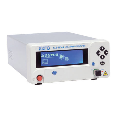
EXFO FLS-5834A User manual

EXFO
EXFO USER GUIDE User manual

EXFO
EXFO FIP-500 User manual
EXFO
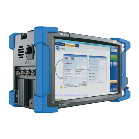
EXFO FTB-2 Operation and maintenance manual
EXFO
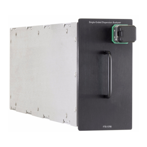
EXFO FTB-5700 User manual

EXFO
EXFO Burleigh Wavemeter WA-1100 User manual

EXFO
EXFO FTB-2 Operation and maintenance manual
EXFO
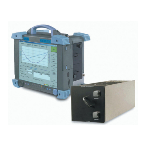
EXFO FTB-5800 User manual
EXFO
EXFO Optical Xplorer OX1 User manual

EXFO
EXFO LTK-1 User manual

EXFO
EXFO OSA20 User manual
EXFO
EXFO PM-1100 User manual
EXFO
EXFO PPM-350B User manual

EXFO
EXFO ETS-1000G User manual
EXFO
EXFO FTB-5240S User manual
EXFO
EXFO OmniCure R2000 User manual

EXFO
EXFO IQS-1100 User manual
