2
DTP T 3G-SDI 230/330 D • Setup Guide (Continued)
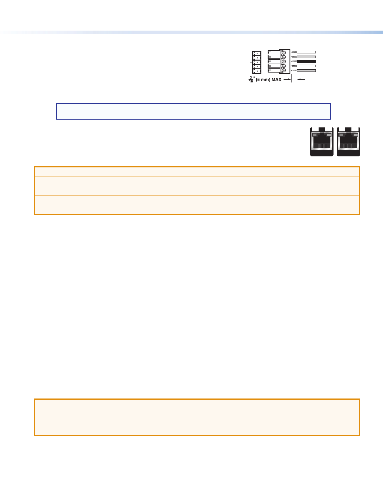
D Over TP connector — Plug an RS-232 or modulated IR device into this
RS-232/IR pass-through port. Wire the cable as shown to the right.
E USB Config port — Connect a PC to this mini USB-B port for device
conguration and rmware updates.
GHDBaseT/DTP mode switch — Set this 2-position, recessed switch to
congure the output between HDBaseT and DTP modes.
When congured for HDBaseT, use an HDBaseT-compatible receiver.
When congured for DTP, use a DTP-compatible receiver.
NOTE: Prior to setting the switch, ensure that the transmitter and receiver are both powered off and that
the correct DTP or HDBaseT receiver is connected.
Step 4 — Run Cables Between Units
Connect the rear panel transmitter output (see F on page 1) to the rear panel receiver input using shielded
twisted pair (STP) cable.
ATTENTION:
• Do not connect these outputs to a telecommunications or computer data network.
• Ne connectez pas ces appareils à des données informatiques ou à un réseau de télécommunications.
• Do not use Extron UTP23SF-4 Enhanced Skew-Free AV UTP cable or STP201 cable.
• N’utilisez pas le câble AV Skew-FreeUTP version améliorée UTP23SF d’Extron ou le câble STP201.
For optimal performance, Extron highly recommends the following:
zRJ-45 termination with STP cable must comply with TIA/EIA T 568B wiring standard for all connections. For more
information on cable wiring and termination, see the full product user guide at www.extron.com.
zUse shielded twisted pair cable, 24 AWG solid conductor or better, with a minimum cable bandwidth of 400 MHz.
zUse shielded RJ-45 plugs to terminate the cable.
zLimit the use of RJ-45 patches. Overall transmission distance capabilities vary depending on the number of patches
used. If possible, limit the number of patches to a maximum of 2.
zIf RJ-45 patches must be used in the system, shielded CAT 6 (or better) patches are recommended.
Step 5 — Connect Outputs from the Receiver
The DTP T 3G-SDI 230/330 D series is compatible with DTP 230 and DTP 330 receivers (sold separately).
a. Output connector — Connect a DP or HDMI cable between this port and the input port of the display. For complete
instructions on connecting receivers or switchers to outputs, see the user guide for the appropriate product at
www.extron.com.
b. Audio output — Connect a stereo audio device to this 3.5 mm mini stereo jack to receive the passed through
unbalanced audio.
c. RS-232/IR Over TP connector — Plug an RS-232 or modulated IR device into the RS-232/IR pass-through port.
Wire the connector as shown in step 3 above.
Step 6 — Power the Units
ATTENTION:
• Extron recommends installing the DTP T 3G-SDI into a grounded, UL Listed electrical junction box.
• Extron recommande d’installer le DTP T 3G-SDI dans un boîtier d’encastrement électrique mis à la terre,
listé UL.
When congured for DTP mode via the rear panel switch (see G on page 1), the unit can be powered either locally, with the
included external 12 VDC power supply, or over the DTP line by a locally powered receiver or switcher.
When congured for HDBaseT mode, remote power capability is disabled and the unit must be powered locally.
SIG LINK
OUT
SIG LINK
IN
Rear Panel TP Ports
Ground
Receive pin on connected unit
Transmit pin on connected unit
Connected RS-232
and IR Device Pins
Tx/Rx
Pins
Receive pin on connected unit
Transmit pin on connected unit
RxTx
RS-232 IR
RxTx
G
OVER TP


