manuals.online logo
Brands
  1. Home
  2. •
  3. Brands
  4. •
  5. Extron electronics
  6. •
  7. Projector Accessories
  8. •
  9. Extron electronics System 8 Plus Instruction manual

Extron electronics System 8 Plus Instruction manual

Extron • System 8/10 P
LUS
• User’s Manual • P/N 68-400-01 Rev. B
Electrohome Configuration and Connections
SYSTEM 8/10 Plus
PROJECTOR COMMUNICATIONS KIT
ATTENTION!
PLEASE READ THIS DOCUMENT FOR IMPORTANT
INSTALLATION INSTRUCTIONS
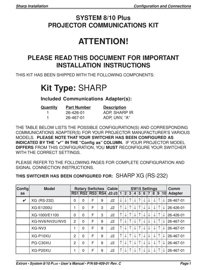
THIS KIT HAS BEEN SHIPPED WITH THE FOLLOWING COMPONENTS:
Kit Type: ELECTROHOME
Included Communications Adapter(s):
Quantity Part Number Description
1 26-474-01 ADP, UNV, “F”
1 26-467-01 ADP, UNV, “A”
1 26-477-01 ADP, UNV, “H”
THE TABLE BELOW LISTS THE POSSIBLE CONFIGURATION(S) AND CORRESPONDING
COMMUNICATIONS ADAPTER(S) FOR YOUR PROJECTOR MANUFACTURER’S VARIOUS
MODELS. PLEASE NOTE THAT YOUR SWITCHER HAS BEEN CONFIGURED AS INDI-
CATED BY THE “✔”IN THE “Config as” COLUMN. IF YOUR PROJECTOR MODEL DIF-
FERS FROM THIS CONFIGURATION, YOU MUST RECONFIGURE YOUR SWITCHER
WITH THE CORRECT SETTINGS.
PLEASE REFER TO THE FOLLOWING PAGES FOR COMPLETE CONFIGURATION AND
SIGNAL CONNECTION INSTRUCTIONS.
THIS SWITCHER HAS BEEN CONFIGURED FOR: ELECTROHOME MARQUEE/
VISTA/HAL
Config Model Rotary Switches Cable SW15 Settings Comm
as RS1 RS2 RS3 RS4 J2/J3 1 2 3 4 5 6 7 8 9 10 Adapter
✔Electrohome Marquee 0 0 5 6 J2 ↓↓↑↓↑↓↓↑↑↓26-474-01
✔Electrohome Vista 0 0 5 6 J2 ↓↓↑↓↑↓↓↑↑↓26-467-01
✔Electrohome Hal 0 0 5 6 J2 ↓↓↑↓↑↓↓↑↑↓26-467-01
Electrohome EPS 0 0 F E J2 ↓↓↑↓↑↓↓↓↑↓26-477-01
Extron • System 8/10 P
LUS
• User’s Manual • P/N 68-400-01 Rev. B
Electrohome Configuration and Connections
Electrohome Marquee/Vista/Hal Projector Configuration
Check to see if the System 8/10 PLUS is already configured for the Marquee/
VistaPro/Hal projector. The general setup is explained on page 3-4 and the
switch settings for the projector are repeated below.
1. Use a small screwdriver to remove the access cover from the System 8/10 PLUS
front panel. See bottom of page 3-3. The label on the back of the access cover
also has the configuration information.
__________ Before changing anything, remove the AC power cord to the System 8/10 P
LUS
to verify that the main power is OFF; also turn the projector power OFF.
2. Set the switches as follows:
Config Model Rotary Switches Cable SW15 Settings Comm
as RS1 RS2 RS3 RS4 J2/J3 1 2 3 4 5 6 7 8 9 10 Adapter
✔Electro. Marquee 0 0 5 6 J2 ↓↓↑↓↑↓ ↓↑↑↓ 26-474-01
✔Electro. Vista 0 0 5 6 J2 ↓↓↑↓↑↓ ↓↑↑↓ 26-467-01
✔Electro. Hal 0 0 5 6 J2 ↓↓↑↓↑↓ ↓↑↑↓ 26-467-01
_ When connecting the
projector for Video Loopback
(VLB) operation SW15, DIP
switch #8 must be Down.
See page 3-4 for switch
description, and page 2-10
for VLB operation.
RS5 is for RGB switching
delay. See page 3-4 for
more information on switch
functions.
3. Use a grease pencil (or other rub-off marker) to mark the space on
the label next to “Marquee” or “VistaPro” or “Hal”.
4. Locate the switcher’s Address DIP switches on the rear panel, lower right.
Unless this is part of a host/peripheral system, set #3 and #5 to the up position
and the others down. See illustration to the left.
Use the illustration on the following page to do the following steps.
5. Connect the Comm Adapter’s 9-pin male connector to the 9-pin female
“Switcher” connector on the rear panel of the projector.
6. Connect the CC-50' (or CC-100') cable from the 9-pin male connector of the
Comm Adapter to the 15-pin HD “Projector Control” port located on the rear
panel of the System 8/10 PLUS.
______ Secure the screws on all D connectors.
7. Connect the BNC (RGBS) cables from the System 8/10 PLUS outputs to the
Marquee/VistaPro projector inputs according to the application requirements.
8. Apply Main Power to the System 8/10 PLUS by connecting the power cord. The
Main Power LED should light. Apply power to the projector.
9. Return System 8/10 PLUS and projector to normal operation.
Configured For:
RS-232
3456 7891012
SW15 DIP Switch
ON
RS5 RS2
RS2
RS1
RS3
RS4
RS1
RS3 RS4
Page 1
Extron • System 8/10 P
LUS
• User’s Manual • P/N 68-400-01 Rev. B
Electrohome Configuration and Connections
15-Pin HD
CC 50'
26-474-01
"F"
9-Pin
3, 4 or 5 BNC
Electrohome Marquee Projector
RS-232
In Out To
Switcher
Red Green Blue Hor/Comp Vert
Sync
"F"
Electrohome Marquee Series Projector Connections
Use the illustration below when connecting the System 8/10 PLUS to a Marquee
projector. Refer to Electrohome Marquee documentation to continue the
installation.
_ If the installation includes looping
(
host/peripheral
) switchers, see
Chapter 5.
If Video Loop Back is part of the
installation, see pages 2-10 and 2-11.
Channel List The Marquee/VistaPro projector
software allows the user to program
the projector slot and input numbers
to match the System 8/10 PLUS input
numbers.
Turn the projector on and use the
Marquee/VistaPro remote to display
the channel list shown in the picture
to the
right.
Use the
arrow
keys to
edit the
list. Press Exit
when finished.
Electrohome Vista/Hal Series Projector Connections
Use the illustration below when connecting the System 8/10 PLUS to a VistaPro
projector. Refer to Electrohome Vista/Hal documentation to continue the
installation.
CC50'
STATUS
POWER
REMOTE NETWORK IN
NETWORK OUT
SPARE
SWITCHER
RED GREEN BLUE H/C SYNC V SYNC
DAT 1
SYNC AUDIO
R
L
IN OUT
DAT 1
RS-232
AUDIO
L
R
IN IN
VID-1 VID-2
VID 2
S-VIDEO
VID 1
COMP. VIDEO
9-Pin HD
S-VIDEO (Y)
COMP VIDEO
S-VIDEO (C)
26-467-01
"A"
15-Pin HD
9-Pin HD
"A"
Page 2
Extron • System 8/10 P
LUS
• User’s Manual • P/N 68-400-01 Rev. B
Electrohome Configuration and Connections
Page 3
Electrohome EPS Projector Configuration
Check to see if the System 8/10 PLUS is already configured for the Marquee/
VistaPro/Hal projector. The general setup is explained on page 3-4 and the
switch settings for the projector are repeated below.
1. Use a small screwdriver to remove the access cover from the System 8/10 PLUS
front panel. See bottom of page 3-3. The label on the back of the access cover
also has the configuration information.
__________ Before changing anything, remove the AC power cord to the System 8/10 P
LUS
to verify that the main power is OFF; also turn the projector power OFF.
2. Set the switches as follows:
Config Model Rotary Switches Cable SW15 Settings Comm
as RS1 RS2 RS3 RS4 J2/J3 1 2 3 4 5 6 7 8 9 10 Adapter
Electrohome EPS 0 0 F E J2 ↓↓↑↓↑↓ ↓↓↑↓ 26-477-01
3. Use a grease pencil (or other rub-off marker) to mark the space on the label next
to “EPS”.
4. Locate the switcher’s Address DIP switches on the rear panel, lower right.
Unless this is part of a host/peripheral system, set #3 and #5 to the up position
and the others down. See illustration to the left.
Use the illustration on the facing page to do the following steps.
5. Connect the Comm Adapter’s 9-pin male connector to the 9-pin female “RS-
232C” connector on the rear panel of the projector.
6. Connect the CC-50' (or CC-100') cable from the 9-pin male connector of the
Comm Adapter to the 15-pin HD “Projector Control” port located on the rear
panel of the System 8/10 PLUS.
______ Secure the screws on all D connectors.
7. Connect the BNC (RGBS) cables from the System 8/10 PLUS outputs to the EPS
projector inputs according to the application requirements.
8. Apply Main Power to the System 8/10 PLUS by connecting the power cord. The
Main Power LED should light. Apply power to the projector.
9. Return System 8/10 PLUS and projector to normal operation.
Configured For:
RS-232
3456 7891012
SW15 DIP Switch
ON
RS5 RS2
RS2
RS1
RS3
RS4
RS1
RS3 RS4
Extron • System 8/10 P
LUS
• User’s Manual • P/N 68-400-01 Rev. B
Electrohome Configuration and Connections
Electrohome EPS Projector Connections
Use the illustration below when connecting the System 8/10 PLUS to an EPS
projector. Refer to Electrohome documentation to continue the installation.
_ If the installation includes looping (
host/peripheral
) switchers, see Chapter 5. If Video Loop
Back
is part of the installation, see pages 2-10 and 2-11.
Page 4
RS - 232C
Side Panel
Rear Panel
RGBHV 5 BNC
9-Pin Female
CommAdapter
26-477-01 "H"
S-Video
Adapter
RCA Adapter
15-Pin
Male
Composite
Video
S-Video
H

Other manuals for System 8 Plus

5

This manual suits for next models

1

Other Extron electronics Projector Accessories manuals

Extron electronics PMK 350 User manual

Extron electronics

Extron electronics PMK 350 User manual

Extron electronics Pole Mount Kit PMK 450 User manual

Extron electronics

Extron electronics Pole Mount Kit PMK 450 User manual

Extron electronics PMK 350 User manual

Extron electronics

Extron electronics PMK 350 User manual

Extron electronics HC 403 EU User manual

Extron electronics

Extron electronics HC 403 EU User manual

Extron electronics MediaLink MLC Plus 100 User manual

Extron electronics

Extron electronics MediaLink MLC Plus 100 User manual

Extron electronics PMK 450 Quick start guide

Extron electronics

Extron electronics PMK 450 Quick start guide

Extron electronics System 8/10 Plus Instruction manual

Extron electronics

Extron electronics System 8/10 Plus Instruction manual

Extron electronics Extron SS 200 User manual

Extron electronics

Extron electronics Extron SS 200 User manual

Extron electronics USFM 100 User manual

Extron electronics

Extron electronics USFM 100 User manual

Extron electronics PMP Series User manual

Extron electronics

Extron electronics PMP Series User manual

Extron electronics PCM 340 User manual

Extron electronics

Extron electronics PCM 340 User manual

Extron electronics PCM 240 User manual

Extron electronics

Extron electronics PCM 240 User manual

Extron electronics PCM 240 User manual

Extron electronics

Extron electronics PCM 240 User manual

Extron electronics PCM 240 User manual

Extron electronics

Extron electronics PCM 240 User manual

Popular Projector Accessories manuals by other brands

Elite Screens VMAX110UWH2 E24 manual

Elite Screens

Elite Screens VMAX110UWH2 E24 manual

GABOR UPM-360 user manual

GABOR

GABOR UPM-360 user manual

Draper Micro Projector Lift Installation and operating instructions

Draper

Draper Micro Projector Lift Installation and operating instructions

Da-Lite Multi Format Imager Instruction book

Da-Lite

Da-Lite Multi Format Imager Instruction book

Elite Screens Spectrum 2 Series user guide

Elite Screens

Elite Screens Spectrum 2 Series user guide

Premier Mounts PBC- UMW Specification sheet

Premier Mounts

Premier Mounts PBC- UMW Specification sheet

Wize EA Series instruction manual

Wize

Wize EA Series instruction manual

Panasonic ET-LAL510 operating instructions

Panasonic

Panasonic ET-LAL510 operating instructions

Christie LX380 instruction sheet

Christie

Christie LX380 instruction sheet

Premier Mounts FTP installation instructions

Premier Mounts

Premier Mounts FTP installation instructions

HRT Huddle Hub One Configuration guide

HRT

HRT Huddle Hub One Configuration guide

Screen Innovations Transformer owner's manual

Screen Innovations

Screen Innovations Transformer owner's manual

CHIEF HB-35B installation instructions

CHIEF

CHIEF HB-35B installation instructions

Cisco MX200 G2 installation guide

Cisco

Cisco MX200 G2 installation guide

InFocus SP-CEIL-003 installation instructions

InFocus

InFocus SP-CEIL-003 installation instructions

Cetacea Sound CEIL-90-3 supplementary guide

Cetacea Sound

Cetacea Sound CEIL-90-3 supplementary guide

Volfoni Smart Crystal user guide

Volfoni

Volfoni Smart Crystal user guide

Panamorph CineVista installation manual

Panamorph

Panamorph CineVista installation manual

manuals.online logo
manuals.online logoBrands
  • About & Mission
  • Contact us
  • Privacy Policy
  • Terms and Conditions

Copyright 2025 Manuals.Online. All Rights Reserved.