Extron • System 8/10 PLUS • User’s Manual • P/N 68-409-01 Rev. C
Sharp Installation Configuration and Connections
Page10
Sharp NV3 Projector Configuration
Verify that the System 8/10 Plus is already configured for the Sharp NV3
projector by following the procedure and switch settings below. The general
setup is explained on page 3-4 of your System 8/10 Plus User’s Manual.
1. Use a small screwdriver to remove the access cover from the System 8/10 Plus
front panel. Refer to page 3-3 of the User’s Manual.
__________ Before changing anything, remove the AC power cord to the System 8/10 Plus
and also turn the projector’s power OFF.
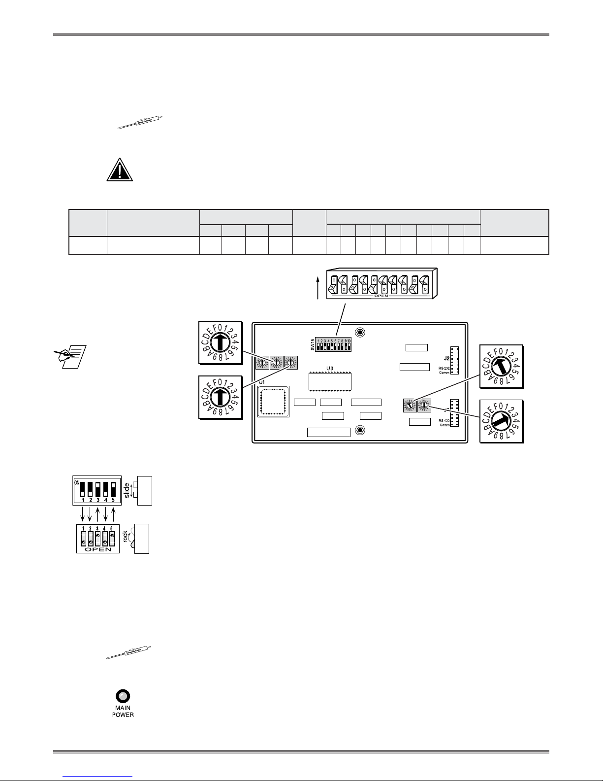
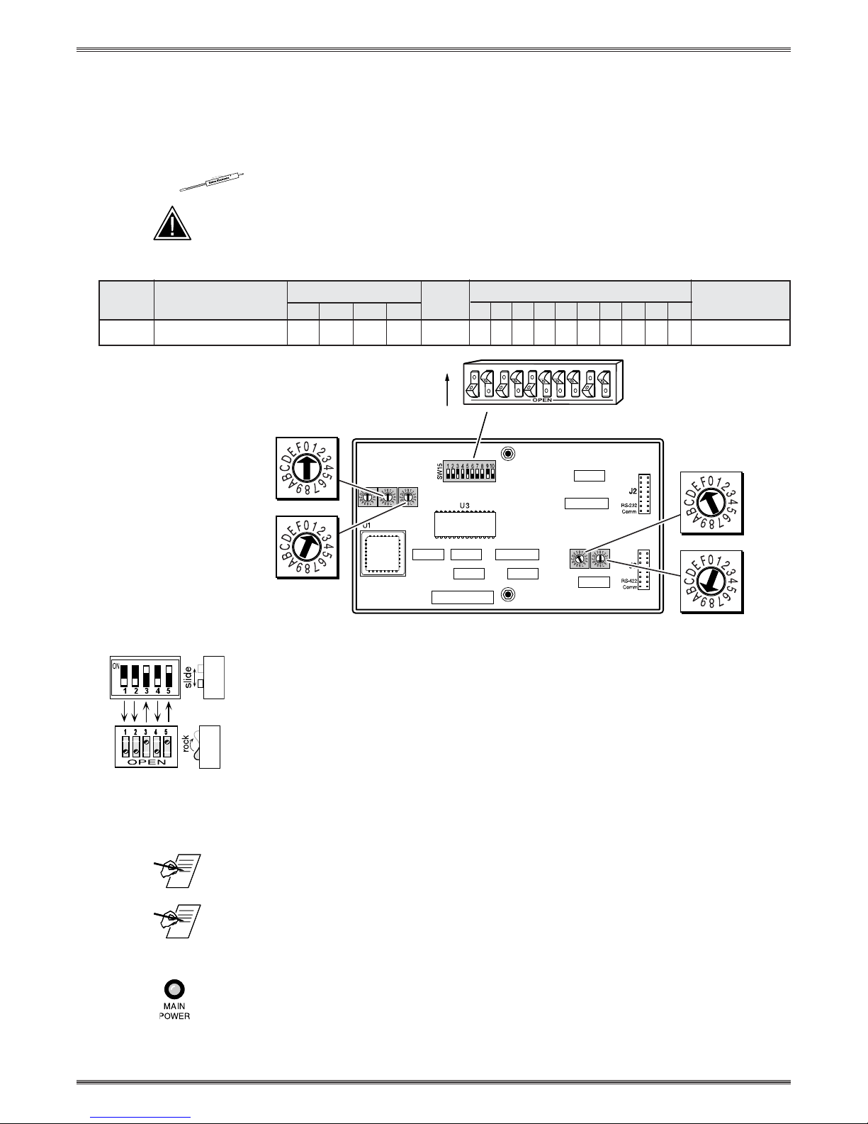
2. Set the System 8/10 Plus switches as follows:
Config Model Rotary Switches Cable SW15 Settings Comm
as RS1 RS2 RS3 RS4 J2/J3 1 2 3 4 5 6 7 8 9 10 Adapter
4Sharp NV3 1 0 F 9 J2 ↑↓ ↑ ↓↑↓ ↓↓
¯↑↓ 26-467-01
3. Locate the switcher’s Address DIP switches on the rear panel, lower right.
Unless this is part of a master/slave system, set #3 and #5 to the up position and
the others in the down position. See illustration on the left.
4. Use the illustration on the following page and continue with the steps below.
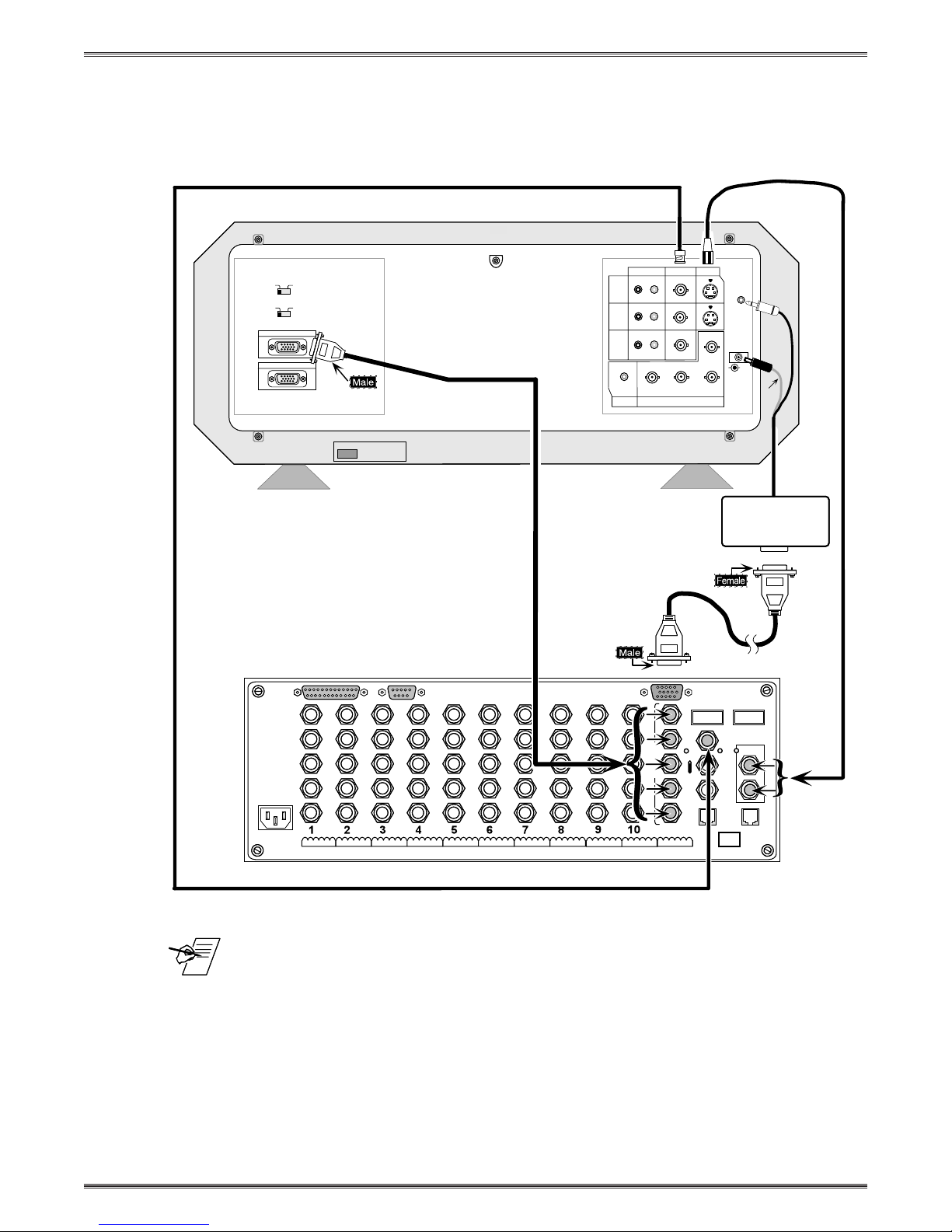
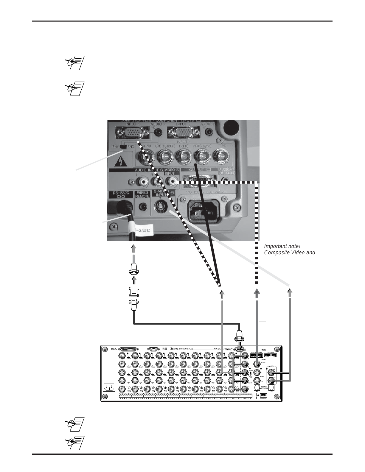
5. Connect the video cables from the System 8/10 Plus outputs to the projector
inputs according to the application requirements (RGBS, S-Video or Composite
Video). One end of the Universal Comm adapter plugs into the IOIOI port of the
Sharp PC Control adapter. The Sharp PC Control adapter plugs into the
projector’s PC Control port 1.
________ The projector’s RGB BNC input will not accept rates lower than VGA or higher
than XGA. Please refer to your projector user manual.
________ Because the projector’s video port will only select S-Video when connected to an
S-Video source, you should not input S-Video and Composite Video sources
simultaneously since Composite Video will be ignored.
6. Apply Main Power to the System 8/10 Plus by connecting the power cord. The
Main Power LED should light. Apply power to the projector.
7. Installation is now completed.
Configured For:
RS-232
SW15 DIP Switch
ON
RS5 RS2
RS2
RS1
RS3
RS4
RS1
RS3 RS4
34567891012