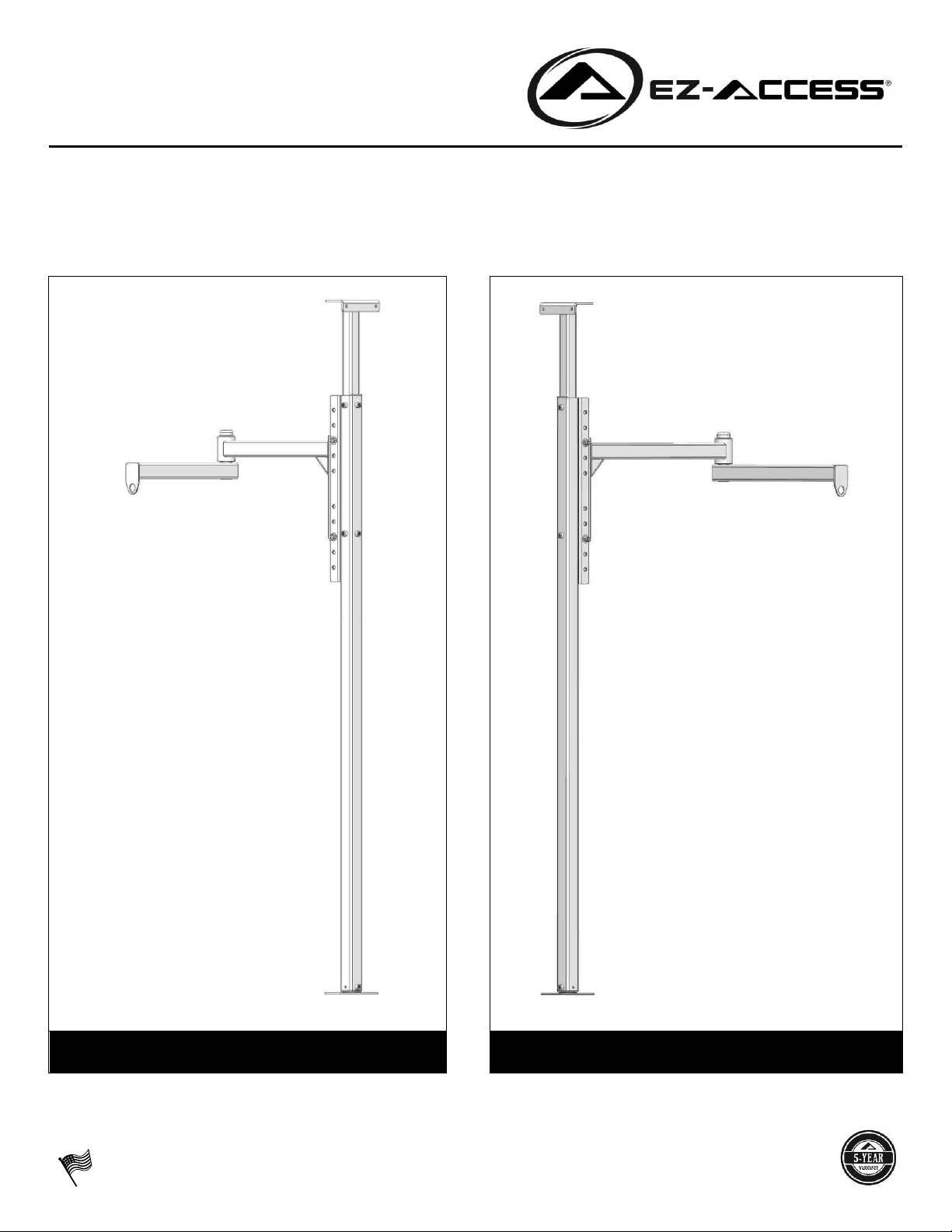
EZ-ACCESS® ORBIT™Patient Transfer Lift
SYMBOL MEANINGS and WARNINGS!
The WARNING symbol indicates a potentially hazardous condition/situation. The safety warnings throughout
this manual, and on your equipment, if any, are for the protection of people and property. Failure by any
system user to abide by safety warnings will result in a waiver of all liabilities, loss of your warranty, and could
result in equipment damage and or failure, property damage, risk of serious bodily injury, and or death. The
symbol may appear in various colors and in conjunction with other symbols. For clarification, a “system user” is
any person using/operating the system.
The NOTE symbol indicates important information. Failure to obey all notes could result in improper operation,
less-than-optimum ORBIT performance, and at the sole discretion of EZ-ACCESS, may void your warranty. The
symbol may appear in various colors and in conjunction with other symbols.
WARNINGS
RATED LOAD: 440 lbs.
Never exceed the RATED LOAD. The RATED LOAD specified is for the ORBIT only and does NOT include ancillary
equipment such as motor, sling, etc.
Before installation and use, read and follow all instructions, labels, and safety warnings. Correct installation,
proper adjustment and use, and following all instructions and warnings are necessary for safe ORBIT operation.
For additional care, use, or safety information, or to obtain replacement copies of labels and instructions, call 1-
800-451-1903 or visit www.ezaccess.com. Maintaining all labels and manuals in legible condition is required by
the ORBIT owner and is essential for safe ORBIT operation. Do not remove ORBIT safety labels.
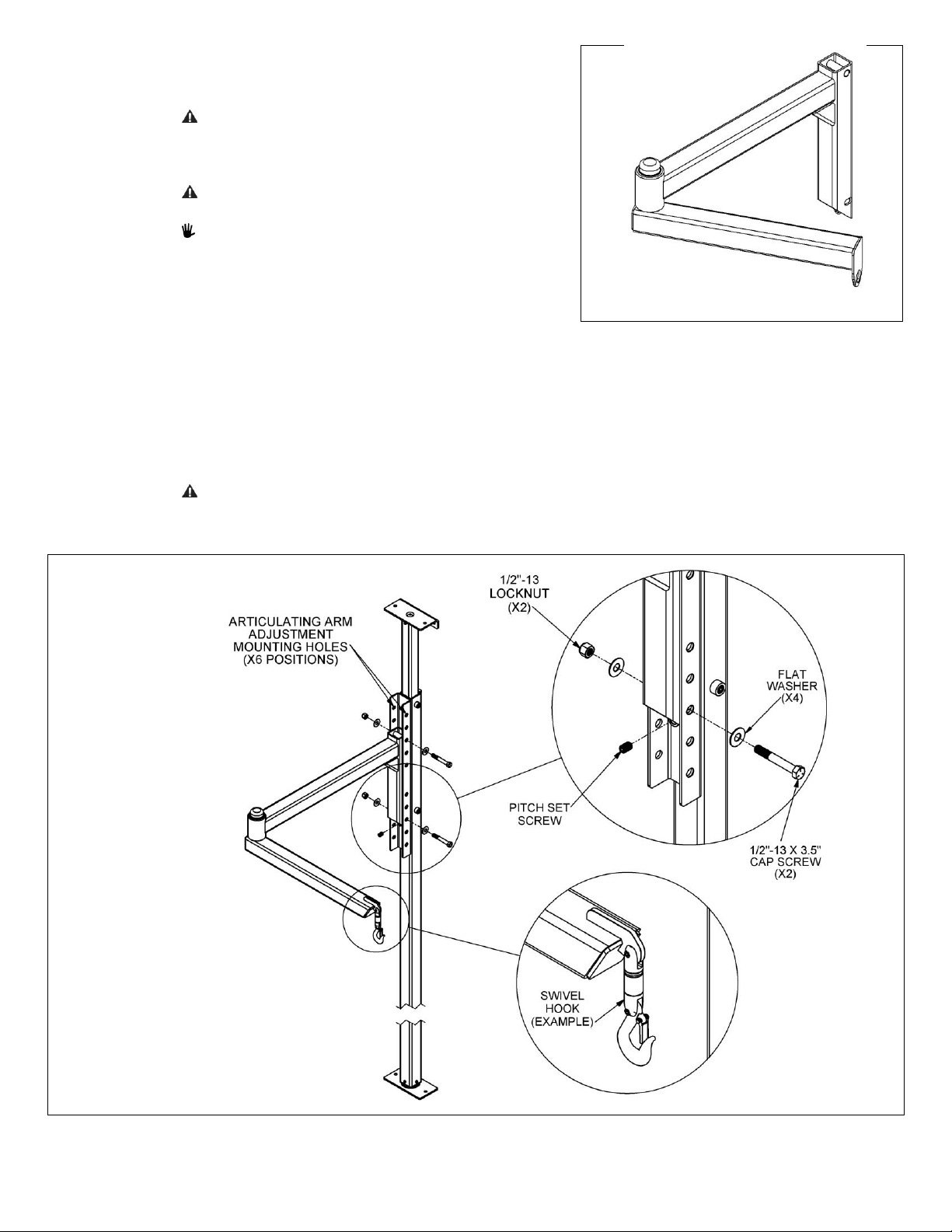
Do not use the ORBIT until installation is fully complete and always use caution throughout the
installation/assembly process. Until the Brake has been set/adjusted, the stanchion may rotate. Correspondingly,
until Articulating Arm is correctly pitched and leveled, it may free-swing. Please use caution at all times.
Before using ancillary equipment, refer to your ancillary equipment’s (motor, sling, etc.) Owner Guide for proper
use. Never exceed ancillary equipment’s manufacturer recommendations.
Professional installation by a contractor is recommended.
The ORBIT must be properly installed and anchored before operation. Improper installation and or use of the
ORBIT can be hazardous.
The ORBIT is NOT a transport device. Use only to transfer an individual from one resting spot to another (such as
bed to wheelchair).
Periodic inspection of the ORBIT and mounting hardware is vital. Verify that the lift is undamaged and secure
before each use.
Do not attempt to repair or modify any part of the ORBIT including damaged fasteners or components; only
qualified technicians may install/service the ORBIT. Contact your dealer for additional information and to
schedule maintenance, inspections, repairs, or service.
Tampering or modifying any portion of the lift will void the warranty and may result in a hazardous situation.
Do not play on or around the ORBIT.
Turn electronic devices used with the ORBIT “OFF” and activate the Emergency Stop before loading or unloading
patients. Never operate equipment with the ORBIT that has damaged electrical wires, cords, or plugs.
Observe and avoid all pinch points.
Never install or use the ORBIT in a manner which pinches electrical cords or causes other safety concerns.
Before and during ORBIT operation, ensure hair, jewelry, shirts, ties, shoe laces and all other forms of clothing
and other personal ornamentation are not, and will not, catch on anything and create a hazard.
The installer is responsible for ensuring the suitable structural integrity of all mounting surfaces and best
anchoring method for the ORBIT. The lift can be mounted to most materials, provided material is structurally
sound and will remain structurally sound throughout the use of the ORBIT. Take into consideration patient
loading and unloading points and rotational radius.
The best time to determine equipment installation and attachment technique is during the on-site
evaluation.
Installer must verify ORBIT Stanchion will be installed perpendicular to the ground/gravity plane.
Installer must verify ORBIT installation will allow travel without interference, obstruction, or safety hazard to
others.
Do not use the ORBIT or its components for anything other than their intended purpose of lifting a single
individual. Do not use to support, attach, or hang planters, lights, decorations, clothing, fabrics or other
furnishings.
Use the ORBIT only with a qualified helper.
The articulating arm swings freely; a qualified helper must maintain control of patient at all times.