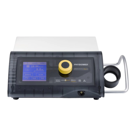
Physiomed IONOSON-Basic User manual

01750 GB
OPERATING INSTRUCTIONS
IONOSON-Basic
MAINS-OPERATED MODEL
BATTERY-OPERATED MODEL

Legal Notice
Distribution, reproduction and translation of the software and its documentation (or excerpts thereof) are
prohibited without the prior written consent of PHYSIOMED ELEKTROMEDIZIN AG.
PHYSIOMED ELEKTROMEDIZIN AG reserves the right to change the software and associated data as well
as the documentation without notice. All other rights reserved.
PHYSIOMED ELEKTROMEDIZIN AG
Hutweide 10
D-91220 Schnaittach/Laipersdorf (Germany)
Phone: +49 9126 2587-0
Fax: +49 9126 2587-25
E-Mail: [email protected]
Internet: http://www.physiomed.de
IONOSON-Basic is made in Germany in compliance with the quality requirements of EN ISO
13485:2003+AC:2007, EN ISO 9001:2008 and the applicable safety standards and regulations of the
Council Directive 93/42/EEC of 14 June 1993 concerning medical devices.
The compliance with the regulations mentioned here is indicated by the CE label on the instrument. The
declaration of conformity might be requested from the manufacturer at the address given above.
A conformity check acc. to Annex II, approved by the notified body 1275, was carried out.
Last updated December 10, 2010

Table of Contents
Chapter1 Introduction.................................. 1
1.1 ConventionsUsed.................................1
1.2 InstrumentSymbols................................1
1.3 InstrumentOverview ...............................2
1.4 GeneralNotes...................................3
1.5 InstrumentDescription ..............................3
1.6 Application ....................................4
1.7 Contraindications.................................4
Chapter 2 Controls and Indicators. . . . . . . . . . . . . . . . . . . . . . . . . . . 6
2.1 Display<1>....................................6
2.1.1 Symbols in the Display <1> . . . . . . . . . . . . . . . . . . . . . . . . . . . . 6
2.2 DataSelector<2>.................................7
2.3 Intensity Control Channel 1 <3> and Channel 2 <4>. . . . . . . . . . . . . . . 7
2.3.1 Automatic Output Current Switch-off. . . . . . . . . . . . . . . . . . . . . . . 7
2.4 Patient Current Indicator <5> . . . . . . . . . . . . . . . . . . . . . . . . . . . 8
2.5 OutputIndicator<6>...............................8
2.6 MainsModule<7>................................8
2.7 PowerSwitch<8>.................................9
2.8 Patient Lead Connector <9> . . . . . . . . . . . . . . . . . . . . . . . . . . . 9
2.8.1 Patient Lead: Mode of Attachment . . . . . . . . . . . . . . . . . . . . . . . . 9
2.9 Ultrasound Lead Connector <10>. . . . . . . . . . . . . . . . . . . . . . . . . 9
2.10 Manual Release Key Socket <11> . . . . . . . . . . . . . . . . . . . . . . . . 10
Chapter 3 Overview of Current Modes . . . . . . . . . . . . . . . . . . . . . . . . 11
3.1 Settings for all Current Modes . . . . . . . . . . . . . . . . . . . . . . . . . 11
3.2 DualChannelOperation............................. 11
3.2.1 Simultaneous and Alternating Stimulation . . . . . . . . . . . . . . . . . . . 12
3.3 Low-Frequency Current Modes . . . . . . . . . . . . . . . . . . . . . . . . . 15
3.3.1 (G)Galvanization................................ 15
3.3.2 (GMC) Galvanization with Microcurrent . . . . . . . . . . . . . . . . . . . . 16
3.3.3 (DF) Diadynamic Current Diphasé Fixe . . . . . . . . . . . . . . . . . . . . . 17
3.3.4 (MF) Diadynamic Current Monophasé Fixe . . . . . . . . . . . . . . . . . . . 18
3.3.5 (CP) Diadynamic Current Modulé en Courtes Périodes . . . . . . . . . . . . . 18
PHYSIOMED ELEKTROMEDIZIN AG Table of Contents
IONOSON-Basic i

3.3.6 (LP) Diadynamic Current Modulé en Longues Périodes . . . . . . . . . . . . . 19
3.3.7 (UR) Ultra Stimulation Current. . . . . . . . . . . . . . . . . . . . . . . . . . 20
3.3.8 (HV) High-Voltage Current . . . . . . . . . . . . . . . . . . . . . . . . . . . 21
3.3.9 (TENS) Transcutaneous Electric Nerve Stimulation. . . . . . . . . . . . . . . . 23
3.3.10 (MENS) Electric Nerve Stimulation with Microcurrent . . . . . . . . . . . . . . 24
3.3.11 (IG30) Pulse Galvanization 30 . . . . . . . . . . . . . . . . . . . . . . . . . . 25
3.3.12 (IG50) Pulse Galvanization 50 . . . . . . . . . . . . . . . . . . . . . . . . . . 26
3.3.13 (FM) Frequency-Modulated Current. . . . . . . . . . . . . . . . . . . . . . . 27
3.3.14 (STOCH) Stochastic Current . . . . . . . . . . . . . . . . . . . . . . . . . . . 29
3.3.15 (FaS) Faradic Surge Current . . . . . . . . . . . . . . . . . . . . . . . . . . . 30
3.3.16 (T/R) Pulses with Adjustable Parameters. . . . . . . . . . . . . . . . . . . . . 32
3.4 Medium Frequency Current Modes . . . . . . . . . . . . . . . . . . . . . . . 33
3.4.1 (IFM) Modulated Interference Current . . . . . . . . . . . . . . . . . . . . . 33
3.4.2 (AMF) Amplitude-Modulated Medium-Frequency Current . . . . . . . . . . . 34
3.4.3 (KOTS) Medium-Frequency Muscle Training. . . . . . . . . . . . . . . . . . . 36
Chapter 4 Operation of the instrument . . . . . . . . . . . . . . . . . . . . . . . 38
4.1 Mains and Battery Operation . . . . . . . . . . . . . . . . . . . . . . . . . . 38
4.1.1 Notes on Handling the Batteries. . . . . . . . . . . . . . . . . . . . . . . . . 38
4.1.2 EconomyMode................................. 39
4.2 Start-up of the Instrument. . . . . . . . . . . . . . . . . . . . . . . . . . . . 39
4.3 FunctionCheck................................. 39
4.4 MonitoringNotes................................ 39
4.5 Constant Current Operation . . . . . . . . . . . . . . . . . . . . . . . . . . 40
Chapter 5 Therapy with Stimulation Current . . . . . . . . . . . . . . . . . . . . 41
5.1 GeneralInformation............................... 41
5.2 Safety Precautions when Attaching Electrodes . . . . . . . . . . . . . . . . . 41
5.2.1 Modes of Attaching the Electrodes . . . . . . . . . . . . . . . . . . . . . . . 42
5.3 Safety Precautions for Stimulation Current Intensity . . . . . . . . . . . . . . 42
5.3.1 Recommended Intensities . . . . . . . . . . . . . . . . . . . . . . . . . . . . 42
5.4 Preparations and Attaching the Electrodes . . . . . . . . . . . . . . . . . . . 43
5.5 Therapy Using Low-Frequency Current Modes . . . . . . . . . . . . . . . . . 44
5.5.1 Monophase and Biphase Currents . . . . . . . . . . . . . . . . . . . . . . . 44
5.5.2 Iontophoresis .................................. 44
5.5.3 Pain Therapy, Hyperaemisation, Detonisation. . . . . . . . . . . . . . . . . . 46
Table of Contents PHYSIOMED ELEKTROMEDIZIN AG
ii IONOSON-Basic
5.5.4 Muscle Stimulation Using Low-Frequency Currents . . . . . . . . . . . . . . . 47
5.6 Therapy with Medium Frequency Current Modes. . . . . . . . . . . . . . . . 50
5.6.1 Treatment with IFM Current. . . . . . . . . . . . . . . . . . . . . . . . . . . 50
5.6.2 Pain Therapy, Hyperaemisation, Detonisation with AMF Current . . . . . . . . 51
5.6.3 Muscle Stimulation with Medium Frequency Stimulation Currents . . . . . . . 52
Chapter 6 Ultrasound Therapy . . . . . . . . . . . . . . . . . . . . . . . . . . . . . 55
Chapter 7 Simultaneous Therapy . . . . . . . . . . . . . . . . . . . . . . . . . . . 57
Chapter8 IndicationsMenu ..............................59
Chapter 9 Individual Programs . . . . . . . . . . . . . . . . . . . . . . . . . . . . . 61
9.1 SaveProgram.................................. 61
9.2 CallProgram................................... 62
9.3 DeleteProgram................................. 62
AppendixA Annex .....................................64
A.1 Customer Service, Maintenance, Service . . . . . . . . . . . . . . . . . . . . 64
A.2 Cleaning and Disinfection . . . . . . . . . . . . . . . . . . . . . . . . . . . . 64
A.3 Service Life and Disposal. . . . . . . . . . . . . . . . . . . . . . . . . . . . . 64
A.4 Electromagnetic Compatibility. . . . . . . . . . . . . . . . . . . . . . . . . . 65
A.5 Training..................................... 65
A.6 Connecting Additional Instruments . . . . . . . . . . . . . . . . . . . . . . . 65
A.6.1 Vacuum Application Unit . . . . . . . . . . . . . . . . . . . . . . . . . . . . 65
A.7 BasicSettings.................................. 66
A.8 TechnicalData.................................. 67
Appendix B Scope of Delivery and Accessories . . . . . . . . . . . . . . . . . . . . 69
B.1 Scope of Delivery (Mains-Operated Model) . . . . . . . . . . . . . . . . . . . 69
B.2 Scope of Delivery (Battery-Operated Model) . . . . . . . . . . . . . . . . . . 70
B.3 AvailableAccessories.............................. 70
PHYSIOMED ELEKTROMEDIZIN AG Table of Contents
IONOSON-Basic iii

Chapter 1 Introduction
With IONOSON-Basic you have acquired a high-quality and extremely versatile combination therapy instru-
ment. The instrument will only show its true potential, however, if you are well informed about its func-
tions. For this reason, carefully read the Operating Instructions and familiarize yourself with the use of the
instrument.
1.1 Conventions Used
Please note the following typographical conventions in these Operating Instructions:
• Cross references and important terms used for the first time in this document are written in italics.
• Names of menus and symbols on the display are written in bold typeface.
Paragraphs that deserve special attention are highlighted in the following way:
Symbol Type Meaning
Tip Intended to give you some extra hints for more convenient operation
Note Provides background information for better understanding
Important Prevents misunderstandings that might lead to limited operation of the in-
strument or insufficient therapeutical results
Caution Alerts you in cases of possible damage to the instrument or risks of injury
1.2 Instrument Symbols
The meanings of the symbols placed on the instrument are as follows:
Symbol Meaning
CAUTION! Refer to the Operating Instructions and consider the physiological effects
of the parameters!
Application part Type BF, not connected to the protective conductor
Ensure environment-friendly disposal! Instruments must by any means be disposed
of separately from household garbage!
PHYSIOMED ELEKTROMEDIZIN AG 1 Introduction
IONOSON-Basic 1

1.3 Instrument Overview
Legend
1 Indicator 7 Mains Module
2 Data Selector 8 Power Switch
3 Intensity Control Channel 1 9 Patient Lead Connector
4 Intensity Control Channel 2 10 Ultrasound Lead Connector
5 Patient Current Indicator 11 Manual Release Key Socket
6 Output Indicator
1 Introduction PHYSIOMED ELEKTROMEDIZIN AG
2 IONOSON-Basic

1.4 General Notes
IONOSON-Basic may only be operated in dry rooms designed for medical purposes, in accordance with
DIN VDE 0100-710, User Class 1. These are rooms with patient beds, physical therapy rooms and practice
rooms. It complies with the technical specifications of VDE 0750/IEC 60601 and is assigned to class IIa ac-
cording to the Council Directive concerning Medical Devices.
The instrument may only be operated by qualified personnel who have undergone special training. You
must operate the instrument properly, i.e. in accordance with the Operating Instructions.
It is not intended for operation in explosion hazard zones or hydrotherapy rooms. Drastic temperature
changes should be avoided, since condensation could be caused within the instrument. Do not start up
the instrument until it is in temperature equilibrium with its environment!
Operating the instrument in the proximity (e.g. 1 m) of a short-wave or micro-wave therapy unit may
cause output irregularities and should be avoided for this reason. Simultaneous connection of the patient
to high-frequency surgical instrument should also be avoided.
Using the electrodes near the thorax can increase the risk of ventricular fibrillation.
The equipment must be connected to the power supply via an earth wire in order to avoid electrical surge
currents.
The replacement of the lithium battery by insufficiently trained personnel can be dangerous.
CAUTION
Technical changes to the equipment are not admissible and will inevitably lead to loss of ap-
proval as a medical device!
1.5 Instrument Description
IONOSON-Basic is a two-channel combination therapy instrument.
You can apply the whole range of current modes from low to medium frequency including modulated in-
terference current. Therapy modes may be accessed directly or, by a proposed treatment, via the indica-
tions menu (refer to Indications Menu on page 59). Moreover, the instrument enables you to store up to
25 individual treatment programs or current mode sequences (refer to Individual Programs on page 61).
Besides plate electrodes and adhesive electrodes, currents can also be applied using vacuum electrodes.
For this, an external vacuum application unit can be connected (refer to Vacuum Application Unit on page 65
).
Waterproof multifrequency transducers (2.5 and 5.0 cm) made of biocompatible titanium are supplied for
ultrasound electrotherapy in the treatment frequencies 1 and 3 MHz. The instrument can also be used for
simultaneous electrotherapy (stimulation current and ultrasound in a single treatment).
The instrument can be equipped with a rechargeable battery and can then be used as a mobile unit, e.g.
in situations where no connection to the mains is available.
PHYSIOMED ELEKTROMEDIZIN AG 1 Introduction
IONOSON-Basic 3

The function of IONOSON-Basic are controlled by a microprocessor. Essential components are permanently
controlled by the processor and thus faulty operation is prevented. After switching on, all instrument func-
tions are checked during an automatic self-test routine.
The instrument complies with all current safety standards. It meets the requirements of the EC directive
concerning medical devices (93/42/EEC) and is therefore CE-labelled.
1.6 Application
The IONOSON-Basic was designed for the following applications:
Stimulation current therapy
• Pain therapy (analgesia)
• Circulatory stimulation
• Mobilization and muscle stimulation
• Iontophoresis
Ultrasound therapy
• Punctual heat therapy in the area of joints, nerves, tendons and muscles
• Pain treatment in case of arthrosis and non-articular rheumatism
• Trophism improvement in case of posttraumatic conditions and ulcus cruris
• Supporting passive and active exercises
Simultaneous Therapy
• Simultaneous application of stimulation current and ultrasound
1.7 Contraindications
Contraindications to stimulation current therapy or simultaneous treatment:
• Highly inflammatory, fever-prone disorders
• Pregnancy
• Patients with cardiac pacemakers or other implanted stimulators
• Malignant tumours
• Skin lesions
• Implants containing metal parts within the area of treatment
Contraindications to ultrasound or simultaneous therapy:
• Fever-prone disorders and acute inflammatory processes
• Tuberculosis
• Gastric ulcers
• Vascular disorders of the extremities (thrombophlebitis, thrombosis, varicosis)
• Tumours
• Circulatory insufficiency, coronary diseases, cardiac arrhythmia
• Acute articular rheumatism
• Diabetes mellitus
• Septic inflammations
1 Introduction PHYSIOMED ELEKTROMEDIZIN AG
4 IONOSON-Basic

• Conditions following radiothorium treatments, X-ray therapy
• Conditions following laminectomy
• Skin lesions (infections, inflammatory processes, naevi)
• Tumescences at all stages (pre-/postoperative)
• Blood coagulation diseases
• In the area of the brain, spinal cord and eyes
PHYSIOMED ELEKTROMEDIZIN AG 1 Introduction
IONOSON-Basic 5

Chapter 2 Controls and Indicators
The design of IONOSON-Basic allows for easy operation, in combination with a variety of functions. Be-
cause of its small size, the instrument is very easy to transport. It has been designed for operation both in-
side and outside of therapy rooms, and is fed by rechargeable batteries for that reason (only battery oper-
ated model, refer to Mains and Battery Operation on page 38).
All controls and indicators are integrated into the housing, thus allowing for easy cleaning of the instru-
ment's surface and protecting it from dust.
The instrument's microprocessor monitors the safety-related components, prevents from erroneous opera-
tion and checks the instrument after switching it on.
2.1 Display <1>
In the Display <1>, all menu items including the therapy para-
meters of the instrument can be selected in different areas.
You can select the parameters using the Data Selector <2>.
2.1.1 Symbols in the Display <1>
In the Display <1> you find the following symbols:
Symbols in the Lower Status Bar
State of charge of the battery (refer to Mains and Battery Operation on page 38)
Emission of current via the Patient Lead Connector <9>
Emission of current via a connected vacuum application instrument (refer to Vacuum Applic-
ation Unit on page 65)
Commutation between CC mode and CV mode (refer to Constant Current Operation on
page 40)
Individual programs (refer to Individual Programs on page 61)
Quit menu and return to start screen
2 Controls and Indicators PHYSIOMED ELEKTROMEDIZIN AG
6 IONOSON-Basic

2.2 Data Selector <2>
The Data Selector <2> is used to select the therapy parameters and to
operate the instrument by means of the cursor. After switching on the in-
strument, the cursor is located at the current mode Gof the Display <1>.
You can move the cursor to the other menu items by turning the selector
to the right or left. To select a menu, simply press the selector.
To select a parameter, move the cursor to the respective field by turning
the selector. After pressing the selector, the cursor will start flashing. You
will then be able to select the parameters by turning the selector and con-
firm the selected value by pressing the selector again (cursor stops flash-
ing). .
NOTICE
In the ultrasound menu the dose is also selected using the Data Selector <2> (refer to Ultra-
sound Therapy on page 55).
2.3 Intensity Control Channel 1 <3> and Channel 2 <4>
The Intensity Control Channel 1 <3> and Intensity Control Channel 2
<4> serve to set the intensity in the channels I and II in steps of 0.5 mA.
When turning up the intensity of the two intensity controls, the associated
therapy timer in the Display <1> will be started as well.
Convenient Reduction of Intensity
The intensity can automatically be turned down to 0.0 mA: To do so, press the Intensity
Control Channel 1 <3> or Intensity Control Channel 2 <4> until you hear a short signal.
Afterwards, the instrument will automatically reduce the intensity to zero.
2.3.1 Automatic Output Current Switch-off
IONOSON-Basic features an automatic output current switch-off, activated in case the current flow of the
electrodes is interrupted (electrode falls off, connector is disconnected from patient lead etc.). The mes-
sage CHECK ELECTRODES I or CHECK ELECTRODES II will appear in the lower status bar and the cur-
rent will be automatically turned down to a minimum basic current in the respective channel. The timer
stops the therapy time. After eliminating the error, you have to turn the Intensity Control Channel 1
<3> or Intensity Control Channel 2 <4> to the left by one position. The message will disappear and you
can increase the intensity again.
PHYSIOMED ELEKTROMEDIZIN AG 2 Controls and Indicators
IONOSON-Basic 7

2.4 Patient Current Indicator <5>
The diode at the left side of the symbol belongs to channel I, the diode at the
right to channel II. The flashing of the indicators depends on the resistance in
the two channels. In most cases the diodes start flashing exactly at the mo-
ment when the patient starts to have a clear sensation of the current in the
corresponding channel.
Important
If the indicator does not flash during treatment, you need to carry out a self-test routine and
observe whether or not the indicator flashes. If the indicator still does not flash during treat-
ment after the check, the accessories of the corresponding channel should be checked and
replaced if necessary!
2.5 Output Indicator <6>
The Output Indicator <6> tells you to be cautious when handling the electrodes.
CAUTION
When the Output Indicator <6> flashes, the Patient Lead Connect-
or <9> is under voltage!
Make sure you do not touch the electrodes when the current is turned
up!
2.6 Mains Module <7>
The Mains Module <7> with the mains switch, is located at the rear face of the in-
strument. With the mains switch, you can switch the mains voltage of the IONO-
SON-Basic on and off.
Important
For mains supply only use the mains cable provided by the manufac-
turer!
2 Controls and Indicators PHYSIOMED ELEKTROMEDIZIN AG
8 IONOSON-Basic

2.7 Power Switch <8>
If you look at the instrument from the front, the Power Switch <8> is on its
left side. By means of this switch, you can switch the instrument on and off.
After switching on, a selftest is automatically carried out by the instrument
(refer to Function Check on page 39).
2.8 Patient Lead Connector <9>
The Patient Lead Connector <9> on the rear face of the instrument serves to plug
in the patient lead. Plate electrodes, adhesive electrodes or other types of electrodes
are plugged into the patient lead. The Patient Lead Connector <9> also serves to
connect a PHYSIOVAC-Basic vacuum application instrument (refer to Vacuum Ap-
plication Unit on page 65).
2.8.1 Patient Lead: Mode of Attachment
The colours of the connectors facilitate easy and correct attachment of the electrodes to the two channels
and to their polarity:
• The colour of the inner channel symbolizes the colour of the electrode lead: red = channel I, blue =
channel II
• The colour of the outer channel symbolizes the colour of the connector: red = anode (+), blue = cath-
ode (-)
anode (+) channel I
cathode (-) channel I
anode (+) channel II
cathode (-) channel II
2.9 Ultrasound Lead Connector <10>
The ultrasonic transducer is connected via the Ultrasound Lead Connector <10>
on the right-hand side of the instrument. The ultrasonic transducer is automatically
calibrated when it is plugged in or after the initial selection of the ultrasound menu
after switching on the instrument (refer to Ultrasound Therapy on page 55).
The Ultrasound Lead Connector <10> is clearly marked with a blue ring to pre-
vent any danger of confusion with other sockets.
PHYSIOMED ELEKTROMEDIZIN AG 2 Controls and Indicators
IONOSON-Basic 9

Replacing the ultrasonic transducer during treatment will not affect the selected mode of treatment. The
dose, however, will automatically be turned down to zero and has to be increased again when continuing
the treatment.
Automatic Coupling Confirmation
Both transducer and instrument have an optical coupling confirmation, which guarantees
constant and efficient treatment. If the coupling to the tissue of the patient is not efficient
enough, the light at the transducer will start flashing. You can choose between counting only
the effective treatment time or running the timer independently of the coupling (refer to Ba-
sic Settings on page 66).
Ultrasonic Transducer
The ultrasonic transducers (2.5 or 5 cm2) work with the frequencies 1
MHz and 3 MHz. The transducers are automatically calibrated after
connecting or switching on the instrument.
The transducers are watertight and can be used for underwater treat-
ment.
Important
The transducer contains a fragile ceramic piezo-resonator. Avoid shocks to the surface and
take special care that the transducer is not dropped. Hard knocks can alter its physical charac-
teristics!
2.10 Manual Release Key Socket <11>
The Manual Release Key Socket <11> at the front of the instrument serves to
connect the manual release key for intentional exercises or for a therapy pause. The
use of a manual release key may be appropriate when applying the current modes
FaS,T/R and KOTS.
The manual release key can be used as a therapy pause button for all other current modes. When pressing
the release key, the current is switched off immediately.
NOTICE
You can turn up the current only after setting the Intensity Control Channel 1 <3> or In-
tensity Control Channel 2 <4>. The therapy time is interrupted as long as the instrument is
standing by.
2 Controls and Indicators PHYSIOMED ELEKTROMEDIZIN AG
10 IONOSON-Basic

Chapter 3 Overview of Current Modes
NOTICE
All current modes of the instrument are emitted in the constant current mode unless other-
wise specified (refer to Constant Current Operation on page 40). Only in simultaneous treat-
ment (refer to Simultaneous Therapy on page 57) the instrument is automatically switched to
a mixed mode consisting of constant current and constant voltage mode to avoid unpleasant
current sensations when the contact between skin and transducer is interrupted.
3.1 Settings for all Current Modes
The following settings are valid for all current modes:
Duration of therapy stated in minutes and seconds: The therapy duration of the re-
spective channel is preselected with the therapy timer.
Click on the corresponding function of the timer using the Data Selector <2> (the
symbol flashes) and turn the Data Selector <2> to the right or left (possible val-
ues: 1.00 ... 60 min). The respective timer is started when increasing the intensity with
the Intensity Control Channel 1 <3> or the Intensity Control Channel 2 <4>.
If the intensity in a channel is turned down to zero, the timer assigned to the channel
stops. When the therapy time is over, you hear a beep. The intensity of the respective
channel is turned down slowly. During a treatment, the timer automatically sets the
therapy time used last.
Current intensity set: This field displays the intensity of the respective channel in mA
(milliampere) or µA (microampere; only for GMC and MENS current modes).
The bar graph below illustrates the maximum level of intensity you can set. The sign
next to the intensity displayed indicates the polarity of the electrode with the red con-
nector.
3.2 Dual Channel Operation
Most current modes can be applied in dual channel operation. The following current modes support dual
channel operation:
•(UR) Ultra Stimulation Current on page 20
•(HV) High-Voltage Current on page 21
•(TENS) Transcutaneous Electric Nerve Stimulation on page 23
•(IG30) Pulse Galvanization 30 on page 25
•(IG50) Pulse Galvanization 50 on page 26
•(FaS) Faradic Surge Current on page 30
PHYSIOMED ELEKTROMEDIZIN AG 3 Overview of Current Modes
IONOSON-Basic 11

•(FM) Frequency-Modulated Current on page 27
•(STOCH) Stochastic Current on page 29
•(T/R) Pulses with Adjustable Parameters on page 32
•(IFM) Modulated Interference Current on page 33
•(KOTS) Medium-Frequency Muscle Training on page 36
3.2.1 Simultaneous and Alternating Stimulation
In current mode FaS and KOTS you can increase and fade the currents in channel 1 and 2 either simultan-
eously or alternating. Three different modes of coordination are possible (simultaneous,directly altern-
ating and alternating with pauses):
Automatic triggering: Channels 1 und 2 stimulate simultaneously with identical para-
meters.
Manual control ( ): Pressing the manual release key causes simultaneous stimula-
tion in both channels until release.
Manual triggering ( ): Pressing the manual release key causes simultaneous
stimulation in both channels with the length set in T.
Automatic triggering: Channels 1 and 2 provide alternating stimulation in immediate
succession. This is followed by a surge cycle consisting of:
• Increase in channel 1 with the length selected for T
• No pause
• Increase in channel 2 with the length selected for T
• Pause with the length set for R
Manual control ( ): First pressing of manual push button causes stimulation in
channel 1 until release, second pressing causes stimulation in channel 2 until release.
Manual triggering ( ): First pressing of manual push button causes stimulation
in channel 1 with the length set in T. The corresponding pulse in channel 2 follows
automatically without a pause.
Automatic triggering: Channels 1 and 2 provide alternating stimulation, with pauses
defined between increases in channel 1 and 2.
Manual control ( ): First pressing of manual push button causes stimulation in
channel 1 until release, second pressing causes stimulation in channel 2 until release.
Manual triggering ( ): First pressing of manual push button causes stimulation
in channel 1 with the length set in T, second pressing causes stimulation in channel 2
with the length set in T.
How to Make a Treatment with a Preselected Pulse Duration and Pause
(1) In the Display <1>, select a suitable current mode e.g. KOTS.
(2) With the Data Selector <2>, click on the symbol in channel I. The following window opens:
3 Overview of Current Modes PHYSIOMED ELEKTROMEDIZIN AG
12 IONOSON-Basic

Selection window for channel I
(3) With the Data Selector <2>, click first on the symbol R, set the pulse pause (1- 60 s) by turning and
confirm by pressing.
(4) Now use the Data Selector <2> to click on the symbol T, set the pulse duration (1- 60 s or manual
release key) by turning and confirm by pressing it.
(5) Now use the Data Selector <2> to click on the symbol to return to the start menu.
(6) The pulse duration and pulse pause selected are now displayed next to the pulse symbol.
(7) With the Data Selector <2>, click on the symbol in channel II. The following window opens:
Selection window for channel II
(8) First use the Data Selector <2> to click on the Rsymbol, turn to the left until the desired symbol
(simultaneous or alternating stimulation) appears and press to confirm.
(9) Now use the Data Selector <2> to click on the symbol to return to the start menu.
The selected symbol now appear next to the pulse symbol in channel II.
NOTICE
During a pulse pause only turn the intensity slightly to avoid unpleasant muscle reac-
tions.
How to Control the Pulse Currents with the Manual Release Key
(1) In the Display <1>, select a suitable current mode e.g. KOTS.
(2) With the Data Selector <2> click on the symbol in channel I. The following window opens:
Selection window for channel I
(3) With the Data Selector <2> first click on the Rsymbol, rotate to the left until one of the manual
control symbols appears and press to confirm. The symbols have the following meaning:
• : The duration of increase is determined by pressing the manual release key, the pause by
releasing the manual release key.
PHYSIOMED ELEKTROMEDIZIN AG 3 Overview of Current Modes
IONOSON-Basic 13

• : Pressing the key triggers a single pulse of the preset increase duration T.
(4) Now use the Data Selector <2> to click on the symbol to return to the start menu.
The manual release key symbol is now displayed next to the pulse symbol .
Important
If you use the manual release key, you can only turn the intensity up in both channels if
you press the manual release key (security blocking)!
(5) With the Data Selector <2> click on the symbol in channel II. The following window opens:
Selection window for channel II
(6) First use the Data Selector <2> to click on the Rsymbol, turn to the left until the desired symbol
(simultaneous or alternating stimulation) appears and press to confirm.
(7) Now use the Data Selector <2> to click on the symbol to return to the start menu.
The respective symbol for simultaneous or alternating simulation now appears next to the pulse sym-
bol of channel II.
How to Control the Pulse Currents Manually with Preselected Pulse Duration
(1) In the Display <1>, select a suitable current mode e.g. KOTS.
(2) With the Data Selector <2> click on the symbol in channel I. The following window opens:
Selection window for channel I
(3) First use the Data Selector <2> to click on the symbol R, turn to the right until the until the manual
release key symbol appears and press to confirm.
(4) Now use the Data Selector <2> to click on the symbol to return to the start menu.
The manual release key symbol is now displayed next to the pulse symbol .
Important
If you use the manual release key, you can only turn the intensity up in both channels if
you press the manual release key (security blocking)!
(5) Now use the Data Selector <2> to click on the symbol T, set the pulse duration by turning and con-
firm by pressing it.
(6) With the Data Selector <2> click on the symbol in channel II. The following window opens:
3 Overview of Current Modes PHYSIOMED ELEKTROMEDIZIN AG
14 IONOSON-Basic
Table of contents
Other Physiomed Medical Equipment manuals

Physiomed
Physiomed IONOSON-IF-Expert User manual

Physiomed
Physiomed PHYSIOTHERM-S User manual

Physiomed
Physiomed PHYSIOTHERM-S User manual

Physiomed
Physiomed PHYSIOMED-IF-Expert User manual

Physiomed
Physiomed PHYSIOSON-Expert User manual

Physiomed
Physiomed IONOSON-Jubilee User manual

Physiomed
Physiomed Deep Oscillation Personal User manual

Physiomed
Physiomed vocaSTIM-Master User manual

Physiomed
Physiomed Jubilee User manual

Physiomed
Physiomed CHUDO HIVAMAT 200 Personal User manual