FAAC SAFEBEAM User manual

SAFEBEAM
SAFEBEAM
C
E
R
M
E
T
A
Z
I
E
N
D
A
C
E
R
T
I
F
I
C
A
T
A
UNI EN ISO 9001-085

2
SAFEBEAM
La fotocellula ad autoallineamento Safebeam, composta da un Trasmettitore ed un Ricevitore a
raggi infrarossi modulati, è un dispositivo di sicurezza. L’oscuramento del fascio luminoso, provoca il
cambiamento di stato del contatto elettrico sul Ricevitore.
The Safebeam self-aligning photocell is a safety device comprising modulated infrared Transmitter
and Receiver.Breaking the path of the beam causes a switch in the status of the electric contact on
the Receiver.
La photocellule avec alignement automatique Safebeam, composée d’un Emetteur et d’un
Récepteur à rayons infrarouges modulés, est un dispositif de sécurité. L’interruption du faisceau
lumineux, provoque le changement d’état du contact électrique sur le Récepteur.
La fotocélula de autoalineación Safebeam, compuesta por un Transmisor y un Receptor por
rayos infrarrojos modulados, es un dispositivo de seguridad. Al obscurecerse el haz luminoso, cambia
el estado del contacto eléctrico en el Receptor.
I
GB
F
D
E
Alimentation 24VDC / 24VAC
Absorption Tx= 20mA Rx= 30mA
Portée max 20m
IP 54
Temps détection obstacle 13mSec
Type contacts et portée NF 60VA / 24W
Type d’alignement automatique
Angle d’auto-alignement +/- 7° (20 m) +/- 13,5° (5 m)
Température d’utilisation -20°C / +55°C
Installation en saillie
Alimentazione 24VDC / 24VAC
Assorbimento Tx= 20mA Rx= 30mA
Portata max. 20m
IP 54
Tempo rilevamento ostacolo 13mSec
Tipo contatto e portata NC 60VA / 24W
Tipo allineamento automatico
Angolo di autoallineamento +/- 7° (20 m) +/- 13,5° (5 m)
Temperatura ambiente -20°C / +55°C
Installazione a parete
Die Photozelle „Safebeam“, die über eine Selbstausrichtungsfunktion verfügt, besteht aus einer Sende- und
Empfangseinheit mit gemodelten Infrarotstrahlen und wird als Sicherheitsvorrichtung eingesetzt. Durch die Abdeckung
des Lichtbündels wird eine Statusänderung des elektrischen Kontakts auf der Empfangseinheit verursacht.
Power supply 24VDC / 24VAC
Absorbtion Tx= 20mA Rx= 30mA
Sensing range 20m
IP 54
Obstacle detection time 13mSec
Contact type and rating NC 60VA / 24W
Type of alignment automatic
Self-alignment angle +/- 7° (20 m) +/- 13,5° (5 m)
Operating ambient temperature -20°C / +55°C
Installation wall-mounting
Versorgung 24VDC / 24VAC
Verbrauch Tx= 20mA Rx= 30mA
Kapazität max. 20m
Schutzgrad IP 54
Erfassungszeit Hindernis 13mSec
Kontakttyp und Leistung NC 60VA / 24W
Ausrichtung automatisch
Winkelspanne der Selbstausrichtung
+/- 7° (20 m) +/- 13,5° (5 m)
Temperatur am Aufstellungsort -20°C / +55°C
Installation Wandinstallation
Alimentación 24VDC / 24VAC
Absorción Tx= 20mA Rx= 30mA
Capacidad máx. 20m
IP 54
Tiempo de detección obstáculo 13mSeg
Tipo de contacto y capacidad NC 60VA / 24W
Tipo de alineación automática
Ángulo de autoalineación +/- 7° (20 m) +/- 13,5° (5 m)
Temperatura ambiente -20°C / +55°C
Instalación en pared
FOTOCELLULA - PHOTOCELL - PHOTOCELLULE
PHOTOZELLE - FOTOCELULA

3
DICHIARAZIONE CE DI CONFORMITÀ
Fabbricante: FAAC S.p.A.
Indirizzo: Via Benini, 1
40069 - Zola Predosa
BOLOGNA-ITALIA
Dichiara che: Il dispositivo di protezione attiva opto-elettronico mod. SAFEBEAM
•è conforme ai requisiti essenziali di sicurezza delle seguenti direttive :
73/23/CEE e successiva modifica 93/68/CEE
89/336/CEE e successiva modifica 92/31/CEE e 93/68/CEE
Nota aggiuntiva:
Questi prodotti sono stati sottoposti a test in una configurazione tipica omogenea
(tutti prodotti di costruzione FAAC S.p.A.).
Bologna, 01 gennaio 2000 L’Amministratore
Delegato
A. Bassi
E
ADVERTENCIAS
•Cuidado: Es importante para la seguridad de
las personas seguir atentamente todas las
instrucciones.
Una instalación equivocada o un erróneo uso
del producto puede ocasionar graves daños a
las personas.
•Leer atentamente las instrucciones antes de
iniciar la instalación del producto y conservarlas
para referencias futuras.
D
HINWEISE
•Achtung! Zur Gewährleistung der Sicherheit der
Personen müssen unbedingt alle Anweisungen
befolgt werden. werden.
Dieunsachgemäße Installation oder der unsach-
gemäße Gebrauch des Produkts kann zu schwe-
ren Personenschäden führen.
•Vor der Installation des Produkts die Anleitung
aufmerksam durchlesen. Die Anleitung ist
sorgfältig aufzubewahren, damit sie auch zu
einem späteren Zeitpunkt konsultiert werden
kann.
•Lisez attentivement les instructions avant de
commencer l’installation du produit, et gardez-
les pour pouvoir éventuellement vous y reporter
par la suite.
I
F
CONSIGNES
•Attention ! Pour que la sécurité des personnes
soit assurée, il est important de suivre
scrupuleusement toutes les instructions.
Une mauvaise installation ou une mauvaise
utilisation du produit peut causer de graves
dommages aux personnes.
GB
IMPORTANT NOTICE
•Warning! In order to ensure personal safety, it is
important that all instructions be carried out to
the letter.
Incorrect installation or use of product could
cause serious personal injury.
•Before attempting installation, read the
instructions carefully and store in a safe place for
future reference.
I
AVVERTENZE
•Attenzione! È importante per la sicurezza delle
persone seguire attentamente tutta l’istruzione.
Una errata installazione o un errato uso del
prodotto può portare a gravi danni alle persone.
•Leggere attentamente le istruzioni prima di
iniziare l’installazione del prodotto e conservarle
per riferimenti futuri.

4
EC COMPLIANCE DECLARATION
Manufacturer: FAAC S.p.A.
Address: Via Benini, 1
40069 - Zola Predosa
BOLOGNA - ITALY
Declares that: The active optoelectronic safety device model SAFEBEAM
•complies with the essential safety requirements of the following directives :
73/23/EEC and subsequent amendment 93/68/EEC
89/336/EEC and subsequent amendment 92/31/EEC and 93/68/EEC
Additional note:
These products have undergone tests in a typical uniform configuration (all products
manufactured by FAAC S.p.A.).
Bologna, 1 January 2000 Managing
Director
A. Bassi
GB
DECLARATION CE DE CONFORMITÉ
Fabricant : FAAC S.p.A.
Adresse : Via Benini, 1
40069 - Zola Predosa
BOLOGNE - ITALIE
Déclare que: le dispositif de protection active optoélectronique mod. SAFEBEAM
•est conforme aux règles de sécurité visées par les directives suivantes:
73/23/CEE, modifiée 93/68/CEE
89/336/CEE, modifiée 92/31/CEE et 93/68/CEE
Remarque supplémentaire:
Ces produits ont été soumis à un test dans une configuration typique homogène (tous
les produits sont de fabrication FAAC S.p.A.).
Fait à Bologna, le 1 janvier 2000 L’Administrateur
Délégué
A. Bassi
F

5
DECLARACION CE DE CONFORMIDAD
Fabricante: FAAC S.p.A.
Dirección:Via Benini, 1
40069 - Zola Predosa
BOLOGNA-ITALIA
Declara que: El dispositivo de protección activa opto-electrónica mod. SAFEBEAM
•cumple los requisitos esenciales de seguridad de las siguientes directivas:
73/23/CEE y sucesiva enmienda 93/68/CEE
89/336/CEE y sucesivas enmiendas 92/31/CEE y 93/68/CEE
Nota accesoria:
Lossistemasfueronprobados en una configuración típica homogénea(todosproductos
fabricados por FAAC S.p.A.).
Bologna, 1º de enero de 2000. El Administrador
Delegado
A. Bassi
EG-KONFORMITÄTSERKLÄRUNG
Der Hersteller: FAAC S.p.A.
Anschrift: Via Benini, 1
40069 - Zola Predosa
BOLOGNA-ITALIA
erklärt: die aktive optoelektronische Schutzeinrichtung Mod. SAFEBEAM
•entspricht den wesentlichen Sicherheitsanforderungen folgender Richtlinien:
73/23/EWG und nachträglicher Änderung 93/68/EWG
89/336/EWG und nachträglicher Änderung 92/31/EWG sowie 93/68/EWG
Zusatzbemerkung:
Diese Produkte wurden in einer typischen und einheitlichen Konfiguration (Fabrikat
der Produkte durchgehend FAAC S.p.A.) geprüft.
Bologna, den 01. Januar 2000 Der Geschäftsführer
A. Bassi
E
D

6
A
B
1. INSTALLAZIONE
ÜPer un funzionamento ottimale, collocare il
Ricevitore e il Trasmettitore allineati.
ATTENZIONE: Non è possibile installare due
coppie di SAFEBEAM sullo stesso impianto a
causa della caratteristica di autoalli-
neamento. In questi casi utilizzare in
alternativa le PHOTOBEAM.
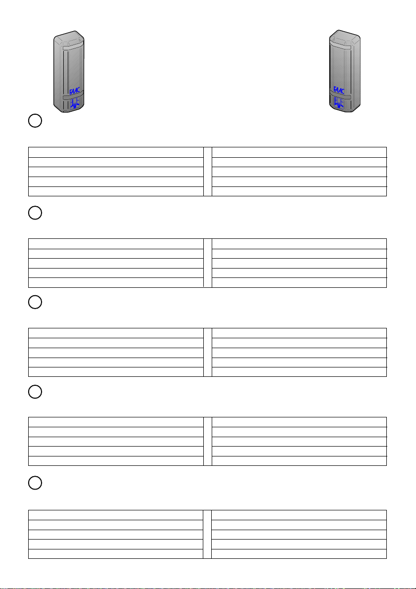
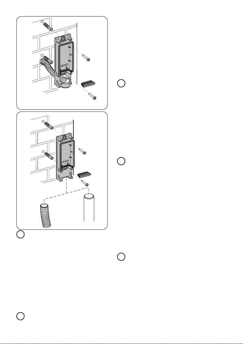
Sono possibili due installazioni:
- A parete con tubo ad incasso (fig.1).
- A parete con tubo/guaina esterni (fig.2).
•Eseguire le predisposizioni per i collegamenti
elettrici.
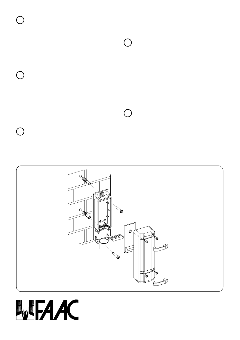
•Fissare i contenitori Safebeam utilizzando viti
e tasselli idonei.
1. MONTAJE
ÜPara un óptimo funcionamiento,colocar el Receptor
y el Transmisor en línea.
ATENCIÓN: No se pueden instalar dos pares de
SAFEBEAM en el mismo equipo, debido a la
característica de autoalineación. En estos casos
utilicen como alternativa las fotocélulas PHOTOBEAM.
Hay dos tipos de instalación posibles:
- En pared con tubo que se encaja (fig.1).
- En pared con tubo/vaina externos (fig.2).
•Realizar las operaciones previas para los enlaces
eléctricos.
•Sujetar los contenedores Safebeam utilizando tornillos
y cuñas adecuadas.
E
1. MONTAGE
ÜZur Gewährleistung des optimalen Betriebs
Empfänger und Sender gefluchtet anordnen.
ACHTUNG: aufgrund der Selbstausrichtungsfunktion
kann nicht mehr als ein Paar der Vorrichtung
„SAFEBEAM“ auf einer Anlage installiert werden.Sollte
dies dennoch erforderlich sein, so sind als Alternative
die Vorrichtungen „PHOTOBEAM“ zu montieren.
Es sind zwei Arten von Installation möglich:
-Wandmontage mit unter Putz verlegtem
Installationsrohr (Abb. 1).
-Wandmontage mit Installationsrohr/Kabel-mantel auf
Putz (Abb. 2)
•Die Vorbereitungen für den elektrischen Anschluß treffen.
•die Behälter der Safebeam einschließlich der
zugehörigen Dichtungen mit Hilfe geeigneter
Schrauben und Dübel befestigen.
D
1. MONTAGE
ÜPour un fonctionnement optimal, placez le
Récepteur et l’Emetteur alignés.
ATTENTION: Il est impossible d’installer deux paires de
SAFEBEAM sur la même installation en raison de
l’alignement automatique caractéristique. Le cas
échéant, utiliser les PHOTOBEAM
.
Il existe deux types d’installation :
- Au mur, à l’aide d’un tube à encastrement (fig.1).
- Au mur, avec un tube/gaine externe (fig.2).
•Effectuez les préparations nécessaires aux
connexions électriques.
•Fixez les conteneurs Safebeam au moyen de vis et
de chevilles adéquates.
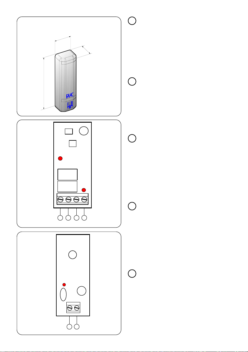
Ø 16 mm
max.
F
Ø 16 mm
max.
efficiency, the Receiver and Transmitter should be
properly aligned.
IMPORTANT: Due to the self-alignment feature, it is not
possible to install two pairs of SAFEBEAM on the same
system. In such cases PHOTOBEAM should be used.
Two types of installation are possible:
- Wall with embedded tube (fig.1).
- With outer tube/sheath (fig.2).
•Carry out the work necessary for the electrical
connections.
•Fix the Safebeam enclosures using suitable screws
and screw anchors.
GB
I
1. FITTING
ÜIn order to ensure optimum working

7
2. ELECTRICAL CONNECTIONS
•Effect the electrical connections on terminal
blocks of Receiver (fig.4) and Transmitter (fig.5)
using the cable duct supplied.
•Connect wiring to the electronic control unit
and any other photocells present in the system.
ÜRefer to the diagrams contained in the
electronic control unit instructions for details of
the various configurations.
GB
2. CONNEXIONS ELECTRIQUES
•Réaliser les connexions électriques sur les
borniers du Récepteur (fig.4) et du Emetteur
(fig.5) en utilisant le passe-câbles fourni.
•Effectuer les câblages électriques à
l’équipement électronique de commande et
aux autres photocellules éventuellement
présentes dans l’installation.
ÜPour les différentes configurations, consulter les
schémas figurant dans les instructions des
appareils.
F
2. ELEKTRISCHE ANSCHLÜSSE
•Die elektrischen Anschlüsse werden auf den
Klemmenleisten der Empfangs- (Abb.4) und der
Sendeeinheit (Abb.5) unter Verwendung der im Lie-
ferumfang enthaltenen Kabelführung ausgeführt.
•Die Verdrahtung mit dem elektronischen
Steuergerät und den ggf. installierten weiteren
Lichtschranken der Anlage vornehmen.
ÜFür die verschiedenen Konfigurationen die
Pläne in den Betriebsanleitungen der Geräte zu
Rate ziehen.
D
2. COLLEGAMENTI ELETTRICI
•Eseguire i collegamenti elettrici sulle morsettie-
re del Ricevitore (fig.4) e del Trasmettitore (fig.5)
utilizzando il passacavo in dotazione.
•Eseguire i cablaggi elettrici all’apparecchiatu-
ra elettronica di comando e ad altre eventuali
fotocellule presenti nell’impianto.
ÜFare riferimento agli schemi riportati nelle
istruzioni delle apparecchiature per le diverse
configurazioni.
I
2. ENLACES ELECTRICOS
•Efectúen las conexiones eléctricas en las
regletas de bornes del Receptor (fig.4) y del Trans-
misor (fig.5) utilizando la guía de cable en
dotación.
•Realizar los cableados eléctricos de la
maquinaria electrónica de mando y de otras
posibles fotocélulas presentes en la instalación.
ÜHacer referencia a los esquemas que
aparecen en las instrucciones de las maquinarias
para las diferentes configuraciones.
E
C
+
-
COMNC
RX
D
DL1
DL2
+
-
TX
E
DL1
2345
12
DIMENSIONI - DIMENSIONS - DIMENSIONS -
ABMESSUNGEN - MEDIDAS
35mm
25mm
105mm
2345
12

8
GB
3. MESSA IN FUNZIONE
a
Alimentare le fotocellule verificando l’accen-
sione del Led DL1 sul Ricevitore (fig.4) e sul Tra-
smettitore (fig.5).
b
Assemblare la Safebeam mediante i partico-
lari a corredo (fig.6).
c
Verificare l’allineamento controllando in tra-
sparenza che anche il Led DL2 sul Ricevitore
(fig. 4) sia acceso.
I
F
E
6
FAAC S.p.A.
Via Benini, 1 40069 Zola Predosa (BO) - ITALIA
Tel. 051/61724-Fax 051/758518-www.faacgroup.com
D
3. START-UP
a
Power up photocells and check that LED DL1
on the Receiver (fig.4) and Transmitter (fig.5) is
lit.
b
Assemble Safebeam using the components
supplied (fig.6).
c
Ensure correct alignment by checking against
the light that LED DL2 on the Receiver (fig. 4) is
also lit.
3. MISE EN FONCTION
a
Alimenter les photocellules en vérifiant
l’allumage de la Led DL1 sur le Récepteur (fig.4)
et sur le Emetteur (fig.5).
b
Assembler la Safebeam au moyen des pièces
fournies (fig.6).
3. INBETRIEBNAHME
aSpannung auf die Photozellen legen und die
Einschaltung der LED-Diode DL1 auf der
Empfangs- (Abb.4) und auf der Sendeeinheit
(Abb.5) überprüfen.
bDie Vorrichtung „Safebeam“ unter Verwen-
dung der im Lieferumfang enthaltenen Teile
zusammenbauen (Abb.6).
cDie Ausrichtung überprüfen, indem anhand
des Lichtstrahls kontrolliert wird, ob auch die
LED-Diode DL2 auf der Empfängereinheit
(Abb. 4) aufleuchtet.
3. PUESTA EN FUNCIONAMIENTO
a
Alimenten las fotocélulas comprobando que
se encienda el indicador DL1 en el Receptor
(fig.4) y en el Transmisor (fig.5).
b
Instalen la fotocélula Safebeam utilizando las
piezas suministradas en dotación (fig.6).
c
Comprueben la alineación verificando en
transparencia que el indicador DL2 en el Re-
ceptor (fig. 4) también esté encendido.
c
Vérifier l’alignement en contrôlant par
transparence que la Led DL2 sur le Récepteur
(fig. 4) est elle aussi allumée.
732988 Rev.A
Table of contents
Other FAAC Accessories manuals
Popular Accessories manuals by other brands

SkyBean
SkyBean SkyDrop user guide

Banner
Banner WORLD-BEAM Expert QS18E Series instruction manual

Changhong Electric
Changhong Electric CHiQ user guide

Weil-McLain
Weil-McLain Gold GV 2 Series Replacement instructions

swiss nights
swiss nights TT-AA instructions

Ace
Ace Lighted Wireless Push Button Accessory... owner's manual