FAAC MSE 110 W User manual

MSE 110 W
MSE 110 W

8
FAAC S.p.A.
Via Benini, 1
40069 Zola Predosa (BO) - ITALIA
Tel.: 051/61724 - Fax: 051/758518
www.faac.it
7325291 Rev. A
Index
DECLARATION OF CONFORMITY ....................................................................................................
p. 2
WARNINGS .....................................................................................................................................
p. 2
1. DESCRIPTION AND TECHNICAL SPECIFICATIONS ..............................................................................
p. 3
2. DIMENSIONS ...................................................................................................................................
p. 3
3. OPERATION .....................................................................................................................................
p. 4
4. ACCESSORIES .................................................................................................................................
p. 4
5. INSTALLING THE DEVICE ..................................................................................................................
p. 4
5.1. TYPES OF INSTALLATION ................................................................................................................................................ p. 4
5.2. POSITIONING AND SIZING THE COMPONENTS ......................................................................................................... p. 5
5.2.1. POSITIONING THE FIXED RECEIVER ................................................................................................................... p. 5
5.2.2. SIZING THE RUBBER PROFILES ............................................................................................................................. p. 5
5.2.3 SIZING THE SUPPORT PROFILE .............................................................................................................................. p. 5
5.3. INSTALLATION SEQUENCE ............................................................................................................................................. p. 5
5.3.1. INSTALLING THE SUPPORT PROFILE .................................................................................................................. p. 5
5.3.2. INSTALLING THE RUBBER PROFILES AND THE RECEIVER/TRANSMITTER ........................................................ p. 6
5.3.3. INSTALLING THE CLOSING CAPS ...................................................................................................................... p. 6
5.3.4. INSTALLING THE FIXED RECEIVER ....................................................................................................................... p. 6
5.3.5. INSTALLING THE COUPLING PROFILE ............................................................................................................... p. 6
6. ELECTRICAL CONNECTIONS ............................................................................................................ p. 7
7. OPERATION DIAGNOSTICS .............................................................................................................. p. 7

9
FAAC S.p.A.
Via Benini, 1
40069 Zola Predosa (BO) - ITALIA
Tel.: 051/61724 - Fax: 051/758518
www.faac.it 7325291 Rev. A
CE DECLARATION OF CONFORMITY
Manufacturer: FAAC S.p.A.
Address: Via Benini, 1 - 40069 Zola Predosa BOLOGNA - ITALY
Declares that: The opto-electronic active protection device mod. MSE110W,
•conforms to the essential safety requirements of the following ECC directives:
EN 12978 - Category 2
73/23/EEC and subsequent amendment 93/68/EEC.
89/336/EEC and subsequent amendment 92/31/EEC and 93/68/EEC
Additionalinformation:
This product underwent a test in a typical, uniform configuration.
(all products manufactured by FAAC S.p.A):
Bologna, 01 January 2006. The Managing Director
A. Bassi
WARNINGS
•Attention! For the safety of people, it is important that all the instructions be carefully observed.
•Incorrect installation or incorrect use of the product could cause serious harm to people.
•Carefully read the instructions before beginning to install the product and keep them for future reference.
•
The symbol indicates notes that are important for the safety of persons and for the good condition of the automated system
•
The symbol draws your attention to the notes on the characteristics or operation of the product.

10
135
42,2
35
135,5
43
24
1. DESCRIZIONE E CARATTERISTICHE TECNICHE
These instructions are valid for the FAAC Mobile Safety Edge
(MSE 110 W).
MSE 110 W is a safety device conforming to European Standard
EN 12978 category 2, and was designed to protect the primary
edge (for opening and closing) of the mobile leaf of a sliding
gate.
Furthermore, it simultaneously performs the functions of a
photocell (EN 12453 C + D).
For installation and operation, scrupulously adhere to
these instructions. Do not use them for any other purpose.
MSE 110 W consists of a mobile and a fixed part:
•The mobile part includes two emitting units (Fig. 1 ref. and )
located at the ends of a rubber profile (Fig. 1 ref. and )
and a receiver-transmitter (Fig. 1 ref.) located in an
intermediate position. All these units operate on lithium batteries
mod. AA.
The rubber profile is sustained by a special support in aluminium
(Fig. 1 ref. ).
•The fixed part consists of a receiver (Fig. 1 ref. ) whose function
is to communicate with the equipment and to signal (with
LEDs) the state of the device to the user.
Support profile
Top cap
Top transmitter
Top rubber profile
Central receiver-transmitter
Bottom rubber profile
Bottom transmitter
Bottom cap
Fixed receiver
MSE 110 W
1. DESCRIPTION AND TECHNICAL SPECIFICATIONS
Fig. 1
TAB. 1 GENERAL TECHNICAL SPECIFICATIONS FOR MSE 110 W
W011ESM
]C°[erutarepmettneibmagnitarepO 55+ot04-
)PI(ssalcnoitcetorP 55
)cesm(emitnoitcetedegdeevitisneS 03
)cesm(emitnoitcetedllecotohP 09
)m(thgiehmumixamegdE 5.2
)m(tniopsseccafohtdiwmumixaM 51
noitacifitreC 2.tac87921NE
TAB. 2 TECHNICALSPECIFICATIONSOFMOBILETRANSMITTER
-RETTIMSNARTELIBOM
dna
ylppusrewopseirettabmuihtiL AA.dom.V5.1x2
)sraey(egnaremiT 3~
langis.ttabgniwollofemitgnitarepogniniameR
)shtnom( 2
)m(rettimsnart/reviecermorfecnatsidmumixaM 5.2
TAB. 4 TECHNICALSPECIFICATIONSOFFIXEDRECEIVER
-REVIECERDEXIF
)cdV(ylppusrewoP 42
]C°[erutarepmettneibmagnitarepO 55+ot04-
stcatnoctuptuofoepyT .C.N1
TAB. 3 TECHNICALSPECIFICATIONSOFMOBILERECEIVER-
TRANSMITTER
-RETTIMSNART-REVIECERELIBOM
ylppusrewopseirettabmuihtiL AA.dom.V5.1x2
)sraey(egnaremiT 3~
langis.ttabgniwollofemitgnitarepogniniameR
)shtnom( 2
)m(reviecerdexifmorfecnatsidmumixaM 51
•
dimensionsinmm
Fig. 2
2. DIMENSIONS

11
A
B
C
D
E
TX1
TX2
RX2
RX1
TX3 RX3
5. INSTALLING THE DEVICE
5.1. TYPES OF INSTALLATION
The fixed receiver can be installed by using various solutions,
according to the type of sliding gate.
The following types of installations can be made with the help of
the accessories shown in Fig. 3:
1) The gate and pillar are on the same axis.
•the receiver is installed directly on the pillar without any
accessory,on the wall (Fig. 4 ref. A ) or embedded (Fig. 4 ref. B).
For installation, see par.5.3.4.
•the receiver is installed inside the coupling profile (Fig.4 ref.C ).
For installation, see the accessory's instructions, par.5.3.5.
2) The gate and pillar are not on the same axis.
•the receiver is installed on the Safe Beam column (Fig. 4 ref. D).
For installation, see the accessory's instructions.
•the receiver is installed on the adjustable support (Fig. 4 ref. E).
For installation, see the accessory's instructions.
4. ACCESSORIES
3. OPERATION
The infra-red ray transmitters (TX1 and TX2), inside the sensitive
edge, communicate with the central receiver-transmitter which,
in turn, communicates with the fixed receiver (RX3).
The interruption of the light beam between emitter and receiver
on the mobile part (following impact against the deformable
profile) or the interruption of the light beam between the mobile
receiver-transmitter and the fixed receiver triggers the safety
edge.
Fig. 3
Column
SAFE BEAM
Support for
fixed receiver
Profile
for coupling
Fig. 4

12
Fig. 6
HT
T
X
L2
L1
LS
Fig. 5
5.2. POSITIONING AND SIZING THE COMPONENTS
When you have chosen the type of installation for the fixed
receiver, size the components as described below.
5.2.1. Positioning the fixed receiver
When the fixed receiver is not installed on the Safe Beam column,
position it so that the lens on the front panel (Fig. 8 ref. ) is 50-
55 cm off the ground. (HT see Fig. 5):
5.2.2. Sizing the rubber profiles
The rubber profile is supplied as a single piece, with a length of
2.5m.
To correctly size the top and bottom rubber profiles, use the
formulas below (all dimensions are in millimeters).
We advise you to cut the rubber profile cleanly and precisely.
Bottom Rubber profile L2:
L2 = HT - T - 63.5
where:
HT = Height between lens of fixed receiver and ground.
T= Distance from ground to finished edge.
Dimension Tmust not be less than 40 mm.
If this dimension were smaller, it would be impossible to
install the bottom cap and, therefore, the installation
would be incomplete.
Top Rubber profile L1:
L1 = X + T - HT - 63.5
where:
X= Total length of finished edge (max. 2500 mm)
T= Distance from ground to finished edge.
HT = Height between lens of fixed receiver and ground.
5.2.3. Sizing the support profile
The support profile in aluminium must be cut using the following
formula:
LS = X - 16
where:
X = Total length of finished edge (max. 2500 mm).
5.3. INSTALLATION SEQUENCE
5.3.1. Installing the support profile
• Precisely drill a 4 mm diam. hole at 8 mm from each end of the
support profile (fig. 6).
These two holes will be used for fastening the support
spacers (fig. 6 ref.
).
•Centre the support profile with respect to the edge to be
protected, leaving 8 mm at each end.
• Drill further 4 mm diam. intermediate holes, in steps of about 40
cm (fig. 6).
• Use the holes to secure the support profile, making sure of the
following:
-Fit the support spacer in the lower hole (fig. 6 ref. ).
-Leave the top hole free (the support spacer will be installed
later on).
-Use screws/expansion plugs suitable for the leaf
construction material.

13
L2
L1
TX1
TX2
45 mm.
135 mm.
Fig. 7
Fig. 8
Fig. 9
5.3.2. Installing the rubber profiles and the receiver/
transmitter.
Fit the batteries (supplied standard) in the top and bottom
transmitters, observing correct polarity (TX1 and TX2 Fig.
7).
•Fit the transmitters on the ends of the rubber profiles, observing
the direction indicated in Fig. 7, with the lens on the front
detection border of the edge.
•Fit the bottom rubber profile, sliding it downward along the
support profile, and taking it in contact against the lower
support spacer.
Fit the batteries (supplied standard) in the receiver-
transmitter observing the polarity (Fig.7A).
•Fit the receiver-transmitter so that the logo is not overturned,
sliding it downward along the support profile, until the rigid
coupling is fully inserted in the rubber profile.
Check if the rubber profile and the receiver-transmitter are in
contact with each other.
•Fit the top rubber profile, sliding it downward along the support
profile, making sure that the rigid coupling is fully inserted in the
rubber profile.
Check if the rubber profile and the receiver-transmitter are in
contact with each other.
•Secure the support spacer in the top hole which had been left
free.
5.3.3. Installing the closing caps
Fit the closing caps, checking if they are in contact with the
rubber profiles, and secure them with the self-tapping screws
(supplied standard) in the pre-drilled holes.
5.3.4. Installing the fixed receiver
Position the receiver so that the lens on the front panel (Fig. 8 ref.
) is 50-55 cm from the ground (HT see Fig. 5):
• Separate the bottom (Fig.8 ref.) from the front panel (Fig.8 ref.)
•Mark, for drilling the holes, the two screw securing points (Fig. 8
ref. ) - screws not supplied.
•Using adequate screws and expansion plugs, secure the
bottom of the receiver (Fig. 8 ref. )
•Make the electrical connections as shown in Chap.6, using
the rubber cable gripper (Fig.8 Ref. )
•Assemble the front cover (Fig. 8 ref. ) to the bottom (Fig. 8 ref.
), using the supplied screws (Fig. 8 ref. )
•Finish installing the receiver, by fitting the rubber protective
devices (Fig. 8 ref. ) on the screws.
•Connect the device using - for cable routing - the facility in the
lower part of the receiver.
5.3.5. Installing the coupling profile
The coupling profile and its aluminium profile must be cut to at
least the same length as the finished edge (dimension Xin Fig. 5).
•We advise you to cut the coupling profile cleanly and
precisely.
Fig. 7A

14
+
-
N.C.
- FSW TX
N.C.
= +
= -
Fig. 10
After you have disaligned a device, the relevant LED
may flash for 2 or 3 seconds at realignment. This brief flashing
should not be considered as a discharged battery signal.
Fig. 11
Tab. 5
NOITISOPDEL NO FFO GNIHSALF
1DEL RETTIMSNARTPOT
DENGILA
RETTIMSNARTPOT
DENGILATON
RETTIMSNART HTIWTUBDENGILA
TSOMLASEIRETTAB
DEGRAHCSID
2DEL
LARTNEC RETTIMSNART
DENGILA
LARTNEC RETTIMSNART
DENGILATON
RETTIMSNART HTIWTUBDENGILA
TSOMLASEIRETTAB
DEGRAHCSID
3DEL
MOTTOB RETTIMSNART
DENGILA
MOTTOB RETTIMSNART
DENGILATON
RETTIMSNART HTIWTUBDENGILA
TSOMLASEIRETTAB
DEGRAHCSID
4DEL 1YALER EVITCA 1YALER EVITCATON ---
5DEL
DERARFNI LANGIS TNEICIFFUS
DERARFNI LANGIS TNEICIFFUSNI ---
6DEL 2YALER EVITCA 2YALER EVITCATON ---
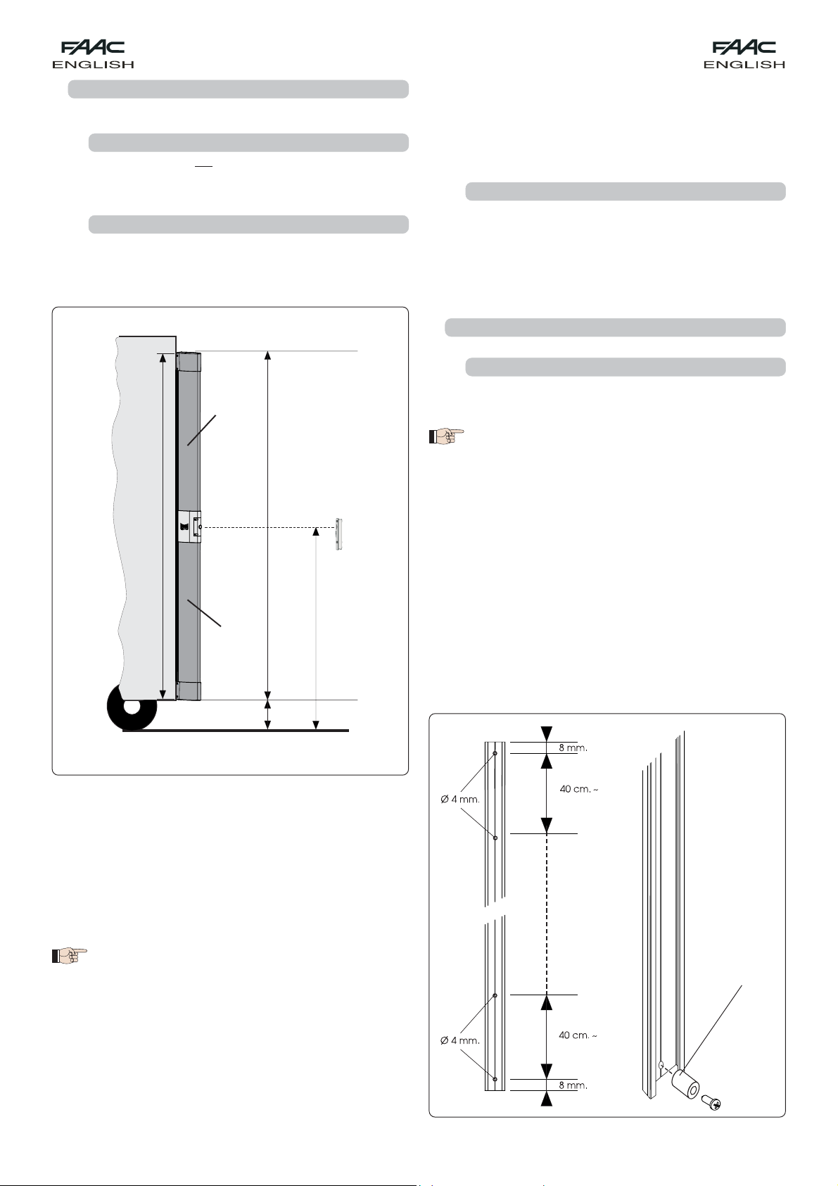
•If you use this profile to install the fixed receiver, you must cut
the front rubber element to create a niche for housing the
receiver at a height of 50 - 55 cm off the ground, using the
supplied drilling template (see Fig. 9).
•Drill a series of 4 mm diam. intermediate holes on the aluminium
profile, in steps of about 40 cm.
•Rest the aluminium profile on the pillar and, to secure it, use the
holes you drilled.
Move the gate manually and check if - in closed position
- the safety edge is positioned on the aluminium profile.
•Insert the rubber coupling profile downward in the aluminium
profile, until the niche reaches the height suitable for positioning
the fixed receiver.
•While moving the gate manually, check if - in closing position -
the edge penetrates inside the rubber coupling profile.
•Prepare the cables for the electrical connection, using the
niche made on the coupling profile (Fig.9).
•Place the electrical cables inside the coupling profile, and
make them exit from the lower part.
•Secure the fixed receiver (par. 4.3.4)
•Finish the installation by fitting the closing caps on the ends of
the coupling profile.
6. ELECTRICAL CONNECTIONS
Make the electrical connections on the terminal-board of the
fixed receiver, consulting the lay-outs in the instructions of the
control units, in the different configurations.
If using equipment without a FAIL SAFE input, you must
connect terminal
to terminal
of the fixed receiver.
7. OPERATING DIAGNOSTICS
The 6 LEDs on the fixed receiver make it possible to diagnose
installation and correct operation of all the devices of safety
edge MSE 110W.
Correct operation and installation is signalled by all 6 LEDs lighting
up on steady beam
For the meaning of each LED, refer to Tab.5.
•If the ray of the receiver-transmitter (Fig. 1 ref. ) is interrupted,
all 6 LEDs go OFF.
•If LED 5 goes OFF, this means:
- The distance between the fixed receiver (Fig.1 ref. ) and
the receiver-transmitter (Fig.1 ref. ) is too long.
- The fixed receiver and the receiver-transmitter are not
correctly aligned.
- The intensity of the signal is not sufficient for correct
operation.
If the MSE110W safety edge is triggered, it causes LEDS 4 and 6 to
go OFF simultaneously.
= Relay contact
= Relay contact
= Fail-Safe


Le descrizioni e le illustrazioni del presente manuale non sono impegnative. La FAAC si riserva il diritto, lasciando inalterate
le caratteristiche essenziali dell’apparecchiatura, di apportare in qualunque momento e senza impegnarsi ad aggior-
nare la presente pubblicazione, le modifiche che essa ritiene convenienti per miglioramenti tecnici o per qualsiasi altra
esigenza di carattere costruttivo o commerciale.
The descriptions and illustrations contained in the present manual are not binding. FAAC reserves the right, whilst leaving
the main features of the equipments unaltered, to undertake any modifications it holds necessary for either technical or
commercial reasons, at any time and without revising the present publication.
Les descriptions et les illustrations du présent manuel sont fournies à titre indicatif. FAAC se réserve le droit d’apporter à
tout moment les modifications qu’elle jugera utiles sur ce produit tout en conservant les caractéristiques essentielles, sans
devoir pour autant mettre à jour cette publication.
Die Beschreibungen und Abbildungen in vorliegendem Handbuch sind unverbindlich. FAAC behält sich das Recht vor,
ohne die wesentlichen Eigenschaften dieses Gerätes zu verändern und ohne Verbindlichkeiten in Bezug auf die
NeufassungdervorliegendenAnleitungen,technisch bzw. konstruktiv/kommerziell bedingteVerbesserungenvorzunehmen.
Las descripciones y las ilustraciones de este manual no comportan compromiso alguno. FAAC se reserva el derecho,
dejando inmutadas las características esenciales de los aparatos, de aportar, en cualquier momento y sin comprometerse
a poner al día la presente publicación, todas las modificaciones que considere oportunas para el perfeccionamiento
técnico o para cualquier otro tipo de exigencia de carácter constructivo o comercial.
De beschrijvingen in deze handleiding zijn niet bindend. FAAC behoudt zich het recht voor op elk willekeurig moment
de veranderingen aan te brengen die het bedrijf nuttig acht met het oog op technische verbeteringen of alle mogelijke
andere productie- of commerciële eisen, waarbij de fundamentele eigenschappen van de apparaat gehandhaafd
blijven, zonder zich daardoor te verplichten deze publicatie bij te werken.
Timbro del Rivenditore:/Distributor’s Stamp:/Timbre de l’Agent:/ Fachhändlerstempel:/Sello del
Revendedor:/Stempel van de dealer:
FAAC S.p.A.
Via Benini, 1
40069 Zola Predosa (BO) - ITALIA
Tel.: 051/61724 - Fax: 051/758518
www.faac.it
www.faacgroup.com
7325291 - Rev. A
Other manuals for MSE 110 W
1
Table of contents
Popular Safety Equipment manuals by other brands

Spanset
Spanset Ergo Jacket Harness instructions

MSA
MSA SURETYMAN SRS15 Application, Operation, Maintenance & Inspection Instructions Manual

Siemens
Siemens SIRIUS 3TK2821 operating instructions

KidKusion
KidKusion 4800 Installation and use instructions

Angel Armor
Angel Armor RISE Use, Care and Maintenance

A.HABERKORN
A.HABERKORN UNI-3 INSTRUCTIONS FOR USE AND TEST MANUAL

Falltech
Falltech FT-R SRL User instruction manual

TEUFELBERGER
TEUFELBERGER GRANIT PRO Manufacturer's information and instructions for use

Tractel
Tractel EN Series Operating and maintenance instructions

GREWIN
GREWIN PCLC-901D manual

Newtec
Newtec 92 A1 INFORMATIVE NOTE

babcockdavis
babcockdavis BFDF Installation, operation and maintenance manual