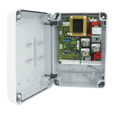
fadini Elpro 27 User manual

®
1
ON
OFF
DIP-SWITCH B
1
ON
OFF
DIP-SWITCH B
meccanica
FADINI
27
Dis. N. 6893
GB
Programmatore elettronico con condensatori motore incorporati; idoneo per
cancelli battenti a una o due ante, con o senza finecorsa e per cancelli
scorrevoli a una o due ante (max. 0,5 CV con frizione meccanica).
Via Mantova 177/A - 37053 Cerea (VR) Italy
Tel. +39 0442 330422 r.a. - Fax. +39 0442 331054
Electronic control box with incorporated motor capacitors; suitable for
oil-hydraulic, single or double swinging gates, with or without limit switches and
for single or double sliding gates (max. 0.5 HP with mechanical clutch).
I
GB
I
GB
I
Programmateur électronique avec condensateurs moteur incorporé; adapté pour
ouvre-portails a battant avec 1 ou 2 vantaux, avec ou sans fin de course et pour
ouvre-portail coulissants avec 1 ou 2 vantaux (max. 0,5 CV avec embrayage mécanique).
F
Elektronische Steueurung mit eingebauten Motor-Kondensatoren; geeignet für
ein-oder zweiflügeligen Drehtore, mit oder ohne Endschaltern und für ein-oder
zweiflügeligen Schiebetore (max. 0,5 PS mit mechanischer Kupplung).
D
F
D
LIBRETTO DI ISTRUZIONI
PER APRICANCELLI SCORREVOLI CON FINECORSA MONOFASE 230V 50/60Hz
A 1 O 2 ANTE pag. 2, 3, 4, 5, 6, 7
INSTRUCTIONS MANUAL
FOR SLIDING GATE OPERATORS WITH LIMIT SWITCHES, S-PHASE 230V 50/60Hz
SINGLE or DOUBLE GATES pages 13, 14, 15, 16, 17, 18
NOTICES D'INSTRUCTIONS
POUR OUVRE-PORTAILS COULISSANTS AVEC FINS DE COURSE MONOPHASE 230V 50/60Hz
AVEC 1 OU 2 VANTAUX pages 24, 25, 26, 27, 28, 29
BETRIEBSANLEITUNG
FÜR SCHIEBETORANTRIEBE MIT ENDSCHALTERN, EINPHASIG 230V 50/60Hz,
MIT EINEM ODER ZWEI TORFLÜGELN Seite 35, 36, 37, 38, 39, 40
F
D
LIBRETTO DI ISTRUZIONI
PER APRICANCELLI A BATTENTE OLEODINAMICI MONOFASE 230V 50/60Hz
A 1 O 2 ANTE pag. 2, 8, 9, 10, 11, 12
INSTRUCTIONS MANUAL
FOR OIL-HYDRAULIC SWINGING ACTUATORS, S-PHASE 230V 50/60Hz
SINGLE or DOUBLE GATES pages 13, 19, 20, 21, 22, 23
NOTICES D'INSTRUCTIONS
POUR OUVRE-PORTAILS A BATTANT HYDRAULIQUES MONOPHASE 230V 50/60Hz
AVEC 1 OU 2 VANTAUX pages 24, 30, 31, 32, 33, 34
BETRIEBSANLEITUNG
FÜR ÖLHYDRAULISCHE DREHTORANTRIEBE EINPHASIG 230V 50/60Hz
MIT EINEM ODER ZWEI TORFLÜGELN Seite 35, 41, 42, 43, 44, 45

page 13
meccanica
FADINI
GB
IN CASE OF FAILURE PLEASE MAKE SURE THAT
- Power supply to the electronic control box is 230V ±10%
- Power supply to the electric motor is 230V ±10%
- All of the fuses is all right
- The photocell contacts are closed
- No voltage drop has occurred from the Elpro board to the electric motor
- All of the NC contacts of the control board are all right
IMPORTANT FOR THE INSTALLATION AND THE CORRECT FUNCTIONING:
- The control box must be installed in a dry and sheltered place; suitable holes are provided with the FADINI universal box for fitting purpose and in
case any commercial box is used, this must be adequate to the job
- Make sure that power supply to the control board be 230V ±10%
- Make sure that power supply to the electric motor be 230V ±10%
- For distances longer than 50 metres increase the section of the wires
- Fit the mains to the control box with a high sensitivity, 0.03A, differential, magnetic-thermal circuit breaker
- Cables with 1.5mm² section wires are to be used for the power supply, electric motor and flasher for distances up to 50 m
- Cables with 1mm² section wires are to be used for the limit switches, photocells, push buttons and accessories
- If no photocells are used link out terminals 1 and 2
- If no stop button is used link out terminals 3 and 6
- Open/Close motor run time trimmer must be always superior to the time actually required for the gate travel
N.W.: For applications such as light switching, CCTV, etc. use solid state relays to prevent the microprocessor from being affected
Diagnostic LEDs:
L ON = Board on 230V voltage and F1, F2, F3 fuses all right
L0 ON = 2nd pair photocells, not obstructed
L1 ON = 1st pair photocells not obstructed
L4 OFF = Open, it switches on by any open pulse
L5 OFF = Close, it switches on by any close pulse
L6 ON = Stop, it switches off by any stop pulse
L7 OFF = Radio, it switches on by any pulse from the transmitter/radio contact
L8 OFF = Pedestrian mode, it switches on by any pedestrian pulsing
L10 ON = Safety edge protecting closing
L30 ON = It switches off when Fc.A. (limit switch Opening = L-sw.O) is engaged, M1
L31 ON = It switches off when Fc.C. (limit switch Closing = L-sw.C) is engaged, M1
L33 ON = It switches off when Fc.A. (limit switch Opening = L-sw.O) is engaged, M2
L34 ON = It switches off when Fc.C. (limit switch Closing = L-sw.C) is engaged, M2
L35 ON = Safety edge protecting opening
ATTENTION: before starting the electrical connections, select the mode of operation depending on gate type
by Dip Switch B N°1 and read the instructions respectively dedicated as follows:
SLIDING gates from page 13 to page 18 - SWINGING gates from page 19 to page 23.
!
Symbols
NC Contact
NO Contact
Led ON
Led OFF
Pilot light
Flasher
27
UNIVERSAL ELECTRONIC CONTROL BOX
SINGLE-PHASE 230V 50/60Hz
General description: the electronic control box ELPRO 27 has been developed to provide a reliable unit to control single or double sliding gate automatic
systems with or without limit switches, as well as single or double swinging gate systems fitted with pressure valves. S-phase 230V 50/60Hz ELPRO 27
complies with the Low Voltage Norms 2006/95 CE and Electro-magnetic Compatibility 2004/108/CE. Installation is recommended by qualified technical
installation agents in compliance with the existing regulations. The manufacturer is not liable for any incorrect use of this appliance; and also reserves
the right to change and update it without previous notice.
ELECTRIC MOTORS
230V SINGLE-PHASE
Power supply
350W max (0.5HP)
M1 M2
F3=2A
24V low
voltage circuit
protection
F2=5A
network
F1=5A
network
COURTESY LAMP
230V MAX 100W
It goes on when gate
starts and stays on for
a fixed time of 90
seconds after motor
run time expiry
TRANSFORMER
1 2 3 4 5 6 7 8 9 10 11 12 13 14 15 16 17 18 19 20 21 22 23 24 25
PLUG-IN
RADIO
CARD
CONNECTOR
2nd pair
photocells
NC
1
st
pair
photocells
radio contact
common
open
close
stop
Indication lamp 24V
max 3W
24Vac output (max. load:
n°1 radio receiver
n°3 pairs photocells)
power supply for
electric lock
15VA max
230Vac OUTPUT
max 25W for flasher
and electric latch
Control board
power supply
230V - 50/60Hz ±10%
24V /ac output
for photocell TX
enabling DSA control
NC
common
common
NEUTRAL
LIVE
26
27
28
CARD
CONNECTOR FOR
TRAFFIC LIGHTS
(Item 7282L)
+_
Power supply
24V - 50mA max.
DC AC
Selector
DC/AC
321
12V
24V
321
Pedestrian opening
LOCK
SETUP
Capacitor
M1 Motor
12.5 µF
Capacitor
M2 Motor
12.5 µF
F4=630mA
Transformer
primary
protection
OUTPUT CONFIGURATION
TERMINALS 14 - 15
UNL
ON
OFF
1 2 3 4 5 6 7 8 9 10 11 12
DIP-SWITCH - A
RUN TIME
OPEN - CLOSE
sliding: 0s - 120s
swinging: 0s - 60s
DWELL
TIME
1s - 220s
- GATE DELAY
CLOSING: 0s - 10s
- OPENING FOR
PEDESTRIANS 1s - 45s
-
+
-
+
-
+
ON
OFF
1 2 3 4
DIP-SWITCH - B
ELPRO 27
UNL
E 27
L4 L5 L6 L7 L8 L10
-
+
ELECTRIC LOCK
TIME
0.5s - 20s
L30 L31 L33 L34
30 31 32 33 34
M1 M2
Fc.A.
Fc.C.
Fc.A.
Fc.C.
35
L35
JA
12
SETUP
EDGE
TYPE
safety edge in closing
common
JB
12
Safety edge
in Opening
8,2 k
or NC
8,2 k
or NC
Resistive contact
8,2 k or NC
L
L0
L1
NOTE:
The green LEDs must
always be on.

page 14
FOR SLIDING GATE SYSTEMS Dip-B N°1=ON
27
Key-switch:
Photocells:
1
DIP-SWITCH-A N° 1:
ON: gate is stopped in opening and reversed
in closing once cleared from obstacle
OFF: gate is not stopped in opening and is
reversed in closing in case of obstacle
Radio Contact
(step by step mode):
Any NO connection to these two terminals
will perform the following:
- Opening only: Dip 2=ON and Dip 5=OFF
- Gate travel reversing by any pulse
Dip 2=OFF and Dip 5=OFF
- Step by step: Open-Stop-Close-Stop
Dip 2=OFF and Dip 5=ON
- No new pulse is accepted in opening.
In Dwell phase and in closing any new
pulse stops and reverses gate travel:
Dip 2=ON and Dip 5=ON
ON: It does not stop and reverse gate travel
in opening
OFF: always stops & reverses in opening
2
ON: step by step with intermediate stop
OFF: gate travel reversed by any radio pulse
5
DIP-SWITCH-A N°2 and N°5:
all of the NC contacts of
the safety accessories
such as the photocells
(receivers) are to be
series connected to
terminals 1 and 2
Accessory Electrical connections
NO and NC contacts to be connected
to the respective terminals in the key-
or button-switches.
All of the possible setting combinations
are described in the instructions sheets
included with the respective control
accessories
NC
NC
1 2
3 4 5 6
FADINI
FADINI
NC
OPEN
CLOSE
STOP
COMMON
RADIO
CONTACT
COMMON
3 7
L1 ON = no obstacle detected, it goes off
in case of obstacle
L4 OFF = no OPENING contact, it goes on
whenever an opening pulse is given
L5 OFF = no CLOSING contact, it goes on
whenever a closing pulse is given
L6 ON = STOP contact closed, it goes
off whenever a stop pulse is given
L7 OFF = no RADIO contact, it goes on
by any radio pulse
Dip-Switch A
1 = ON Photocells stop gate in opening
2 = ON Radio, no reversing in opening
3 = ON Automatic closing
4 = ON Pre-flashing in service
5 = ON Radio step-by-step
6 = ON Traffic lights mode
limit switches connected
ON
OFF
1 2 3 4 5 6 7 8 9 10 11 12
DIP-SWITCH - A
meccanica
FADINI
FOR SLIDING GATE AUTOMATIC SYSTEMS WITH LIMIT SWITCHES:
Dip Switch B N°1= ON
7 = OFF: Blank
8 = OFF: Blank
9 = ON 2nd pair photocells in service
10 = ON Flasher off in Dwell time
11 = ON Gate re-closing in Opening and Dwell on photocells engaging
12 = OFF: Blank
Dip-Switch B
1 = ON SLIDING GATE mode
2 = ON Hold-on-switched control mode (deadman control)
3 = ON Traffic lights on "yellow" for 3 seconds
4 = ON DSA control by Photocell transmitters if connected to the dedicated terminals
2nd pair photocells
(fitted inside perimeter):
Dip A No.9=ON and the NC contact connected: The gates
stay stopped as long as the photocells are obstructed.
- In opening cycle: obstacle removed, gates go on opening
- In closing cycle: obstacle removed, gate travel reversed
NOTE: if no 2nd pair photocells are used, it is not necessary
to bridge the contact input, only DIP-SWITCH-A No. 9=OFF
1 2 3 4
ON
OFF
DIP-SWITCH - B
2 3 4
1
ON
OFF
DIP-SWITCH - B
FADINI
Dip-Switch setting and LED indication of functions
ELECTRICAL CONNECTIONS ON SLIDING GATE MODE - Dip Switch B n°1=ON
12 13
24Vac output max load:
n°1 radio receiver
n°3 pairs photocells
27
UNIVERSAL ELECTRONIC CONTROL BOX
SINGLE-PHASE 230V 50/60Hz
DIP-SWITCH-A N° 9:
ON: Photocells 2nd pair in service
OFF: Photocells 2nd pair not installed
9
L0 ON = no obstacle detected, it
goes off in case of obstacle
This pair of photocells stops gate in opening;
once cleared from obstacle, gate goes on
opening, gate travel is reversed in closing
FADINI
FADINI
123
456
789
AB
STOP
Output for a 24V max 3 W indication lamp
showing the status of the system:
Lamp On = Gate open
Lamp Off = Gate closed
0.5s (fast) flashing = gate closing
1s (normal) flashing = gate opening
Indication lamp
output
24V- max 3W:
COMMON
3 11
GB

page 15
FOR SLIDING GATE SYSTEMS Dip-B N°1=ON
27
meccanica
FADINI
GB
27
UNIVERSAL ELECTRONIC CONTROL BOX
SINGLE-PHASE 230V 50/60Hz
SAFETY EDGES
JA
Accessory Electrical connections LED indication
L10
Normally alight:
whenever the safety edge is engaged,
the LED goes off
JA
12
8,2k Resistive
safety edge
Safety edge
in Closing:
The two inputs, that are fitted to control the safety edges, are separated for the opening and closing phases. Also, it is possible to select the type
of contact connected to them, either N.C. mechanical or 8,2 k resistive, by means of the two jumpers JA1 or JA2.
Thanks to a dedicated microcontroller circuit separately fitted on to the board, the actual integrity and correct functioning of the safety system is
constantly controlled. Any possible fault or loss of efficiency is signalled by the L10 and L35 LEDs keeping flashing.
1 2
NC safety edge
L35
Normally alight:
whenever the safety edge is engaged,
the LED goes off
Safety edge
in Opening:
In series if safety edges
are mechanical, N.C.
9 10 9 10
Selecting functioning:
JB
JB
12
Gate travel is reversed on Opening
and Closing for a short spell.
1 2
Gate travel is reversed in
Opening and Closing for
twice as much the spell.
JB
JB
12
Once the safety edge has been engaged and
the obstacle removed, the gate closes automatically.
(If automatic close mode has been selected).
1 2
Once the safety edge has been engaged and
the obstacle removed, the gate stays stopped
until a new pulse is given.
(Even if automatic close mode has been selected).
In parallel if safety edges
are resistive 8,2 k
Safety edge selection:
JA JA
12
8,2k Resistive
safety edge
1 2
NC safety edge
In series if safety edges
are mechanical, N.C.
In parallel if safety edges
are resistive 8,2 k
Safety edge selection:
32 33 34 35 32 33 34 35
8,2 k
8,2 k
(JA1 jumper)
(JA2 jumper)
(JB1 jumper) (JB2 jumper)

page 16
FOR SLIDING GATE SYSTEMS Dip-B N°1=ON
27
meccanica
FADINI
GB
27
UNIVERSAL ELECTRONIC CONTROL BOX
SINGLE-PHASE 230V 50/60Hz
ELECTRICAL CONNECTIONS ON SLIDING GATE MODE - Dip Switch B n°1=ON
230Vac OUTPUT
Flasher
max 25W
Flasher 230V:
2322
l'apricancello
DIP-SWITCH-A N°4 and N°10:
ON: Pre-flashing before movement
OFF: No pre-flashing
4
ON: Flasher out of service in Dwell time
Automatic mode (Dip 3 = ON)
OFF: Flasher in service in Dwell time
Automatic mode (con Dip 3= ON)
10
PCB Power
Supply 230V:
NEUTRAL
LIVE
24 25
Control board power supply
230V - 50/60Hz ±10%
DWELL TIME
1s - 220s
MOTOR RUN TIME
OPEN - CLOSE
0s - 120s
-
+
-
+
Output for single-
phase motors
230V 350W max -
HP 0.5:
In case of one motor only:
1) Connect power supply to the terminals Motor M1
2) No gate delay in opening by Dip-A N°8=ON
3) Set the trimmer Gate Delay in Closing to zero
M1
COMMON
16 17 18 19 20 21
M2
COMMON
In case of 2motors:
1) Connect power supply to the terminals Motors M1 and M2
2) No gate delay in opening by Dip-A N°8=ON
3) Set the trimmer Gate Delay in Closing to zero
Accessory Electrical connections Dip-Switch setting and LED indication of functions
24V output:
FADINI
Astro 43
FADINI
24V ac OUTPUT - max load:
No. 3 pairs of photocells
No. 1 radio receiver
No. 1 LED Chis 37 / Chis-E 37 key-switch
Instructions are attached to the related control
accessories
12 13
Gate electric lock: 14 15 Power supply output 12Vac/dc or 24Vac/dc
for an electric lock, 15VA max.
STRIP
JUMPER Power supply for a
mechanical release lock.
321
LOCK
SETUP
321
LOCK
SETUP
3 2 1
12V
12V electric lock power supply
3 2 1
24V
24V electric lock power supply
Power supply for a magnetic
lock to hold the gate/s
on gate stop/s.
AC
DC
= alternated current output
= direct current output
ELECTRIC LOCK
TIME
0.5s - 20s
-
+

page 17
FOR SLIDING GATE SYSTEMS Dip-B N°1=ON
27
meccanica
FADINI
27
UNIVERSAL ELECTRONIC CONTROL BOX
SINGLE-PHASE 230V 50/60Hz
ELECTRICAL CONNECTIONS ON SLIDING GATE MODE - Dip Switch B n°1=ON
RED
YELLOW
GREEN
Power supply
230V 50Hz
Red
Yellow
Green
Red
Yellow
Green
1A Fuse
Common
63 64 65 66 60 61
(Optional: Traffic lights
plug-in card for
230V Lamps) Item 7282L
Traffic lights plug-in card (Optional - Item No. 7282L):
The power supply of this card is independent from that of the control board:
230V 50Hz with an output of 100W at 230V each lamp.
Logic of operation:
- GREEN light = driveway OPEN
- RED light = driveway CLOSED
- YELLOW light = it switches on before light changes from green to red
Note: In Pedestrians mode the traffic light is always RED.
Dip-Switch A
4= ON Pre-flashing Enabled: traffic lights Red - Yellow - Green
4= OFF Pre-flashing Disabled: traffic lights Red - Green
6= ON Limit switches installed
6= OFF Limit switches linked out (functioning by time setting)
Dip-Switch B
3= ON Pre-flashing time prolonged by about 2 seconds
(yellow light up to 3 seconds)
3= OFF Standard time as factory-preset
Functioning with 2 lamps (Red and Green):
Dip-Switch A 4 = OFF
Dip-Switch A 6 = adjust setting depending on whether the limit switches are
used or not in the installation
Dip-Switch B 3 = OFF
Accessory Electrical connections LED indication of functions
Double sliding gate limit switches:
L30 ON= OFF on engaging L.sw. Opening M1
L31 ON= OFF on engaging L.sw. Closing M1
L33 ON= OFF on engaging L.sw. Opening M2
L34 ON= OFF on engaging L.sw. Closing M2
Single sliding gate limit switches:
Power connections
to Pulin 3 LEDs: Terminals for
the connections
of the LEDs of the
push buttons
Pulin 3
28 2627
OUTPUT
24Vdc - 5W max
3
24Vdc-5W output:
29 30
+ -
L30 ON= OFF on engaging L.sw. Opening
L31 ON= OFF on engaging L.sw. Closing
L33 ON= OFF on engaging L.sw. Opening
L34 ON= OFF on engaging L.sw. Closing
30 31 32 33 34
common
M1 M2
Opening Limit switch
Closing Limit switch
Opening Limit switch
Closing Limit switch
30 31 32 33 34
comune
Opening Limit switch
Closing Limit switch
In applications where only one motor is fitted,
connect the inputs of the M1 and M2 limit
switches be put in "parallel" (bridge 30 with 33
and 31 with 34, and then connect them to the
limit switches Open - Close).
IMPORTANT: if no limit switches are involved,
link out terminals 30 - 31 - 32 - 33 - 34.
Limit switches ( L-sw.) must have normally
closed contacts.
In applications where two motors are fitted, connect the
normally closed limit switches to the respective input terminals.
IMPORTANT: if no limit switches are involved, link out terminals
30 - 31 - 32 - 33 - 34. Limit switches ( L-sw.) must have normally
closed contacts.
GB

page 18
FOR SLIDING GATE SYSTEMS Dip-B N°1=ON
27
meccanica
FADINI
GB
27
UNIVERSAL ELECTRONIC CONTROL BOX
SINGLE-PHASE 230V 50/60Hz
AUTOMATIC / SEMI-AUTOMATIC:
Automatic Cycle: by one pulse from the open command the gate opens and stops in
Dwell mode for the time as pre-set on the Dwell Trimmer. When this time expires the gate
closes automatically.
Semi-automatic Cycle: by one pulse from the open command the gate opens and
stops in fully open position. To close the gate, a close pulse is needed.
Dip - Switch setting and LED indication of functions
Description
DIP-SWITCH-A N°9 and N°11:
PEDESTRIAN OPENING:
With the gate in fully closed position, a pulse to terminals
3-8 operates the gate for pedestrians.
(On pedestrian mode, it is advisable to set Dip-A N°3= ON
for automatic re-closing).
The function "Pedestrian Opening" is not in service during
the first operation cycle, after a power failure.
FUNCTIONS FOR SLIDING GATE OPENING - Dip Switch B n°1=ON
RE-CLOSING BY PASSING ACROSS THE PHOTOCELLS: in opening and dwell cycles
(DIP-A N°3=ON)
Gate is automatically closed after 3s from passing between the photocells.
In case a second pair of photocells are installed, (Dip 9=ON), both pairs are to be
passed across.
Dwell Trimmer: adjust dwell time
on automatic mode
from 1s up to 220s
3
ON: Automatic closing
DIP-SWITCH-A N°3:
-
+
L8 OFF = no pedestrian contact given,
it goes on by pulsing for pedestrians
OPEN
PEDESTRIANS
11
ON: Automatic closing on passing across
the photocells after 3 seconds
ON: 2nd pair photocells enabled
OFF: 2nd pair photocells not installed
9
OFF: No automatic closing on passing across
the photocells after 3 seconds
4
ON: DSA safety control enabled
OFF: DSA safety control disabled
DIP-SWITCH-B N°4:
DEADMAN (HOLD-ON-SWITCHED) FUNCTION:
The open/close operations are achieved by "holding on a command switched" (the
relays are not self-holding) and consequently the user must be actively present during
gate movements until the push-button or the key-switch is released. 2
ON: Deadman control enabled
OFF: Deadman control disabled
DIP-SWITCH-B N°2:
COMMON
NO
External time clock
3
ON: Automatic closing
DIP-SWITCH-A N°3:
3 4
OPEN
COMMON
24V ac Output
for photocell
transmitter TX
enabled for DSA control
IMPORTANT: use always and only with
Dip-A N°3= ON
PARTY FUNCTION
OPEN-AND-HOLD BY EXTERNAL CLOCK:
Connection: connect the Clock NO contact to OPEN
terminals No. 4 and COMMON No. 3, and activate
automatic closing by Dip-Switch No. 3=ON.
How it works: program the opening time on the clock.
At the preset time, the gate will open and remain open
(the flashing light will turn off) and will not accept any
other command (not even radio commands) until the
time set on the clock expires. When this time expires
the gate closes automatically after the pause time.
While the gate is held open by the time set on the
"clock", the indication light keeps giving out two
consecutive flashes followed by a long pause.
DSA: PHOTOCELL AUTOMATIC CONTROL:
For the DSA control (Device for Safety Auto-test) it is necessary
to connect only the photocell transmitters (TX) to this output
and select Dip-B No.4=ON: if this function is enabled, ELPRO 27
checks that all the connected photocell devices are cleared
from obstacles and properly working before starting any
door/gate movements, otherwise the door/gate is not started.
OFF: Semi-automatic, closing by pulse
-
+
OPENING FOR
PEDESTRIANS
1s - 45s
RIT. C 3 4 5 6 7 8
1615

page 19
FOR SWINGING GATE SYSTEMS Dip-B N°1=OFF
27
Dip-Switch A
1 = ON Photocells stop gate in opening
2 = ON Radio, no reversing in opening
3 = ON Automatic closing
4 = ON Pre-flashing in service
5 = ON Radio step-by-step
6 = ON Traffic lights mode
limit switches connected
ON
OFF
1 2 3 4 5 6 7 8 9 10 11 12
DIP-SWITCH - A
meccanica
FADINI
FOR SWINGING GATE AUTOMATIC SYSTEMS:
set Dip Switch B N°1= OFF
2 3 4
1
ON
OFF
DIP-SWITCH - B
7 = ON Stroke reversing pulse in Opening cycle
8 = ON No gate delay in Opening, motors start together
9 = 2nd pair photocells in service
10 = ON Flasher off in Dwell time
11 = ON Gate re-closing in Opening and Dwell on engaging the photocells
12 = ON Memory of motor run time settings enabled, with installations
where very frequent operations are required
Dip-Switch B
1 = OFF SWINGING GATE mode
2 = ON Hold-on-switched (deadman ) control
3 = ON Traffic lights "yellow" for 3 seconds
4 = ON DSA control by photocell transmitters if connected to the dedicated terminals
1 2 3 4
ON
OFF
DIP-SWITCH - B
27
UNIVERSAL ELECTRONIC CONTROL BOX
SINGLE-PHASE 230V 50/60Hz
Key-switch: NO and NC contacts to be connected
to the respective terminals in the key-
or button-switches.
All of the possible setting combinations
are described in the instructions sheets
included with the respective control
accessories
3 4 5 6
FADINI
FADINI
NC
OPEN
CLOSE
STOP
COMMON
L4 OFF = no OPENING contact, it goes on
whenever an opening pulse is given
L5 OFF = no CLOSING contact, it goes on
whenever a closing pulse is given
L6 ON = STOP contact closed, it goes
off whenever a stop pulse is given
1st pair photocells:
fitted outside
perimeter
1
DIP-SWITCH-A N° 1:
NC
NC
1 2
2nd pair photocells:
fitted inside perimeter 1 2 DIP-SWITCH-A N°9:
9
ELECTRICAL CONNECTIONS ON SWINGING GATE MODE - Dip Switch B n°1=OFF
12 13
12 13
24Vac output max. load:
n°1 radio receiver
n°3 pairs photocells
All NC contacts of safety
accessories such as
Photocells (receivers)
must be connected in
series with terminals
1 and 2
NC
FADINI
FADINI
Accessory Electrical connections Dip-Switch setting and LED indication of functions
ON: Photocells 2nd pair in service
OFF: Photocells 2nd pair not installed
L0 ON = no obstacle detected, it goes off
in case of obstacle
24Vac output max. load:
n°1 radio receiver
n°3 pairs photocells
Dip A No.9=ON and the NC contact connected: The gates
stay stopped as long as the photocells are obstructed.
- In opening cycle: obstacle removed, gates go on opening
- In closing cycle: obstacle removed, gate travel reversed
NOTE: if no 2nd pair photocells are used, it is not necessary
to bridge the contact input, only DIP-SWITCH-A No. 9=OFF
ON: stop gate/s in opening and reverse travel in
closing when cleared
OFF: no stop in opening and reverse travel in
closing when obstructed
L1 ON = no obstacle, it goes off
in case of obstraction
DIP-SWITCH-A N°2 and N°5 :
RADIO
CONTACT
COMMON
3 7
L7 OFF = no RADIO contact, it goes on by
any radio pulse
FADINI
Radio contact
(step by step mode):
Any NO connection to these two terminals
will perform the following:
- Opening only: Dip 2=ON and Dip 5=OFF
- Gate travel reversing by any pulse
Dip 2=OFF and Dip 5=OFF
- Step by step: Open-Stop-Close-Stop
Dip 2=OFF and Dip 5=ON
- No new pulse is accepted in opening.
In Dwell phase and in closing any new
pulse stops and reverses gate travel:
Dip 2=ON and Dip 5=ON
ON: It does not stop and reverse gate travel
in opening
OFF: always stops & reverses in opening
2
ON: step by step with intermediate stop
OFF: gate travel reversed by any radio pulse
5
123
456
789
AB
STOP
Indication lamp
output
24V- max 3W:
COMMON
3 11 Output for a 24V max 3W indication lamp
showing the status of the system:
Lamp On = Gate open
Lamp Off = Gate closed
0.5s (fast) flashing = gate closing
1s (normal) flashing = gate opening
GB

SAFETY EDGES
page 20
FOR SWINGING GATE SYSTEMS Dip-B N°1=OFF
27
meccanica
FADINI
27
UNIVERSAL ELECTRONIC CONTROL BOX
SINGLE-PHASE 230V 50/60Hz
JA
Accessory Electrical connections LED indication
L10
Normally alight:
whenever the safety edge is engaged,
the LED goes off
JA
12
8,2k Resistive
safety edge
Safety edge
in Closing:
The two inputs, that are fitted to control the safety edges, are separated for the opening and closing phases. Also, it is possible to select the type
of contact connected to them, either N.C. mechanical or 8,2 k resistive, by means of the two jumpers JA1 or JA2.
Thanks to a dedicated microcontroller circuit separately fitted on to the board, the actual integrity and correct functioning of the safety system is
constantly controlled. Any possible fault or loss of efficiency is signalled by the L10 and L35 LEDs keeping flashing.
1 2
NC safety edge
L35
Normally alight:
whenever the safety edge is engaged,
the LED goes off
Safety edge
in Opening:
In series if safety edges
are mechanical, N.C.
9 10 9 10
Selecting functioning:
JB
JB
12
Gate travel is reversed on Opening
and Closing for a short spell.
1 2
Gate travel is reversed in
Opening and Closing for
twice as much the spell.
JB
JB
12
Once the safety edge has been engaged and
the obstacle removed, the gate closes automatically.
(If automatic close mode has been selected).
1 2
Once the safety edge has been engaged and
the obstacle removed, the gate stays stopped
until a new pulse is given.
(Even if automatic close mode has been selected).
In parallel if safety edges
are resistive 8,2 k
Safety edge selection:
JA JA
12
8,2k Resistive
safety edge
1 2
NC safety edge
In series if safety edges
are mechanical, N.C.
In parallel if safety edges
are resistive 8,2 k
Safety edge selection:
32 33 34 35 32 33 34 35
8,2 k
8,2 k
(JB1 jumper) (JB2 jumper)
(JA1 jumper)
(JA2 jumper)
GB

page 21
FOR SWINGING GATE SYSTEMS Dip-B N°1=OFF
27
meccanica
FADINI
GB
27
UNIVERSAL ELECTRONIC CONTROL BOX
SINGLE-PHASE 230V 50/60Hz
Accessory Electrical connections Dip - Switch setting and LED indication of functions
Board power
supply 230V:
NEUTRAL
LIVE
24 25
Electronic control board power supply
230V - 50/60Hz ±10%
230Vac OUTPUT for
flashing lamp
max 25W
Electric latch and
flashing lamp 230V:
2322
l'apricancello
DIP-SWITCH-A N°4 and N°10:
ON: Pre-flashing before movement
OFF: No pre-flashing
4
ON: Out of service in Dwell phase
Automatic mode (by Dip 3= ON)
OFF: Powered, ie. in service in Dwell phase
Automatic mode (by Dip 3= ON)
10
230Vac OUTPUT for
electric latch. Important:
power supply must be off
during Dwell time by
Dip-A n°10=ON
Power connections
to Pulin 3 LEDs:
28 2627
3
OUTPUT
24Vdc - 5W max
24Vdc-5W Output:
Terminals for
the connections
of the LEDs of the
push buttons
Pulin 3
29 30
+ -
ELECTRICAL CONNECTIONS ON SWINGING GATE MODE - Dip Switch B n°1=OFF
Output for single-
phase motors
230V 350W max:
In case of one motor only:
1) Connect power supply to the terminals Motor M1
2) No gate delay in opening by Dip-A N°8=ON
3) Set the trimmer Gate Delay in Closing to zero
motor
delayed
in closing
DWELL TIME
1s - 220s
MOTOR RUN TIME
OPEN-CLOSE
0s - 60s
motor
delayed
in opening
M1
COMMON
16 17 18 19 20 21
M2
COMMON
GATE DELAY
IN CLOSING
0s - 10s
In case of 2motors:
Gate delay in Opening, with a fixed time of 2s: if required, it
must be enabled by Dip-A N°8=OFF
DIP-SWITCH-A N°8:
ON: No gate delay in opening
OFF: 2s gate delay in opening enabled
8
-
+
-
+
-
+
Gate electric lock: 14 15 Power supply output 12Vac/dc or 24Vac/dc for an electric lock,
15VA max. The electric lock is to be fitted onto the gate operated
by the M1 motor, delayed in closing cycle.
STRIP
JUMPER Power supply for a
mechanical release lock
321
LOCK
SETUP
321
LOCK
SETUP
3 2 1
12V
12V electric lock
power supply
3 2 1
24V
24V electric lock
power supply
Power supply for a magnetic
lock to hold the gate/s
on gate stop/s
AC
= alternated current
output
DC
= direct current
output
ELECTRIC LOCK
TIME
0,5s - 20s
-
+
24V Output:
FADINI
Astro 43
FADINI
12 13
24V ac OUTPUT - max load:
No. 3 pairs of photocells
No. 1 radio receiver
No. 1 LED Chis 37 / Chis-E 37 key-switch
Instructions are attached to the related control
accessories

page 22
FOR SWINGING GATE SYSTEMS Dip-B N°1=OFF
27
meccanica
FADINI
GB
27
UNIVERSAL ELECTRONIC CONTROL BOX
SINGLE-PHASE 230V 50/60Hz
Accessory Electrical connections LED indication of functions
RED
YELLOW
GREEN
Power supply
230V 50Hz
Red
Yellow
Green
Red
Yellow
Green
Fuse 1A
Common
63 64 65 66 60 61
(Optional: Traffic lights
plug-in card for
230V lamps) item 7282L
Traffic lights plug-in card (Optional - Item No. 7282L):
The power supply of this card is independent from that of the control board:
230V 50Hz with an output of 100W at 230V each lamp.
Logic of operation:
- GREEN light = driveway OPEN
- RED light = driveway CLOSED
- YELLOW light = it switches on before light changes from green to red
Note: In Pedestrians mode the traffic light is always RED.
Dip-Switch A
4= ON Pre-flashing Enabled: traffic lights Red - Yellow - Green
4= OFF Pre-flashing Disabled: traffic lights Red - Green
6= ON Limit switches installed
6= OFF Limit switches linked out (functioning by time setting)
Dip-Switch B
3= ON Pre-flashing time prolonged by about 2 seconds
(yellow light up to 3 seconds)
3= OFF Standard time as factory-preset
Functioning with 2 lamps (Red and Green):
Dip-Switch A 4 = OFF
Dip-Switch A 6 = adjust setting depending on whether the limit switches are
used or not in the installation
Dip-Switch B 3 = OFF
ELECTRICAL CONNECTIONS ON SWINGING GATE MODE - Dip Switch B n°1=OFF
Limit switches: IMPORTANT: if no limit switches
are involved, link out terminals
30 - 31 - 32 - 33 - 34.
Limit switches ( L-sw.) must have
normally closed contacts.
L30 ON= OFF on engaging L.sw. Opening M1
L31 ON= OFF on engaging L.sw. Closing M1
L33 ON= OFF on engaging L.sw. Opening M2
L34 ON= OFF on engaging L.sw. Closing M2
30 31 32 33 34
common
M1 M2
Opening Limit switch
Closing Limit switch
Opening Limit switch
Closing Limit switch

page 23
meccanica
FADINI
GB
FOR SWINGING GATE SYSTEMS Dip-B N°1=OFF
27
UNIVERSAL ELECTRONIC CONTROL BOX
SINGLE-PHASE 230V 50/60Hz
27
3
DIP-SWITCH-A N°3:
RE-CLOSING BY PASSING ACROSS THE PHOTOCELLS: in opening and dwell cycles
(DIP-A N°3=ON)
Gate is automatically closed after 3s from passing between the photocells.
In case a second pair of photocells are installed, (Dip 9=ON), both pairs are to be
passed across.
24V ac Output
for photocell
transmitter TX
enabled for DSA control
1615
FUNCTIONS FOR SWINGING GATE OPENING - Dip Switch B n°1=OFF
-
+
AUTOMATIC / SEMI-AUTOMATIC:
Automatic Cycle: by one pulse from the open command the gate opens and stops in
Dwell mode for the time as pre-set on the Dwell Trimmer. When this time expires the gate
closes automatically.
Semi-automatic Cycle: by one pulse from the open command the gate opens and stops
in fully open position. To close the gate, a close pulse is needed.
DSA: PHOTOCELL AUTOMATIC CONTROL:
For the DSA control (Device for Safety Auto-test) it is necessary to
connect only the photocell transmitters (TX) to this output and
select Dip-B No.4=ON: if this function is enabled, ELPRO 27 checks
that all the connected photocell devices are cleared from obstacles
and properly working before starting any door/gate movements, otherwise
the door/gate is not started.
PEDESTRIAN OPENING:
With the gate in fully closed position, a pulse to terminals
3-8 operates the gate for pedestrians.
(On pedestrian mode, it is advisable to set Dip-A N°3= ON
for automatic re-closing).
The function "Pedestrian Opening" is not in service during
the first operation cycle, after a power failure.
L8 OFF = no pedestrian contact given,
it goes on by pulsing for pedestrians
3 4 5 6 7 8
OPEN
PEDESTRIANS
Dip - Switch setting and LED indication of functions
Description
Dwell Trimmer: adjust dwell time
on automatic mode
from 1s up to 220s
ON: Automatic closing
OFF: Semi-automatic, closing by pulse
DIP-SWITCH-A N°9 and N°11:
11
ON: Automatic closing on passing across
the photocells after 3 seconds
ON: 2nd pair photocells enabled
OFF: 2nd pair photocells not installed
9
OFF: No automatic closing on passing across
the photocells after 3 seconds
4
ON: DSA safety control enabled
OFF: DSA safety control disabled
DIP-SWITCH-B N°4:
DEADMAN (HOLD-ON-SWITCHED) CONTROL:
The open/close operations are achieved by " holding on a command
switched" (the relays are not self-holding) and consequently the user must
be actively present during gate movements until the push-button or the
key-switch is released. 2
ON: Deadman control enabled
OFF: Deadman control disabled
DIP-SWITCH-B N°2:
3
ON: Automatic closing
DIP-SWITCH-A N°3:
COMMON
N.O.
External clock
3 4
OPEN
COMMON
STROKE REVERSING PULSE IN OPENING CYCLE
This function helps the gate electric lock to release with the gate/s in fully closed
position,even in "Pedestrians" mode: the gates in closed position are pushed to close
direction for 2 seconds before the opening cycle begins.
DIP-SWITCH-A N°7:
ON: Stroke reversing pulse in opening enabled
for 2s
OFF: No stroke reversing pulse
7
APPLICATIONS IN BLOCKS OF FLATS:
This is a function for heavy duty applications with frequent inversions of direction: this
function, when enabled, takes into account the remaining motor run time when there is
an inversion of direction or passage between the photocells.
DIP-SWITCH-A N°12:
12
ON:Memory of motor run time settings enabled
OFF: No memory enabled
IMPORTANT: use always and only with
Dip-A N°3= ON
PARTY FUNCTION
OPEN-AND-HOLD BY EXTERNAL CLOCK:
Connection: connect the Clock NO contact to OPEN terminals
No. 4 and COMMON No. 3, and activate automatic closing by
setting Dip-Switch No. 3=ON.
How it works: program the opening time on the clock. At the
preset time, the gates will open and remain open (the flashing
light will turn off) and will not accept any other command (not
even radio commands) until the time set on the clock expires.
When this time expires the gates close automatically after the
pause time.
While the gates are held open by the time set on the "clock",
the indication light keeps giving out two consecutive flashes
followed by a long pause.

La ditta costruttrice si riserva di apportare modifiche al presente libretto senza preavviso
Via Mantova, 177/A - 37053 Cerea (Verona) Italy - Tel. +39 0442 330422 r.a. - Fax +39 0442 331054
®
s.n.c.
Prima dellinstallazione da parte di personale tecnico qualificato, si consiglia di prendere visione del
Libretto Normative di Sicurezza che la Meccanica Fadini mette a disposizione.
Please note that installation must be carried out by qualified technicians following Meccanica Fadinis
Safety Norms Manual.
Linstallation doit être effectuée par un technicien qualifié suivant le manuel des Normes de Sécurité
de Meccanica Fadini.
Vor der Installation durch qualifiziertes tecnisches Personal wird empfohlen das Handbuch zu den
Sicherheitsvorschriften durchzulesen, das die Meccanica Fadini zur Verfügung stellt.
I -
GB -
F -
D -
VIETATO GETTARE NEI RIFIUTI
MATERIALI NOCIVI PER LAMBIENTE
Direttiva 2003/108/CE
Smaltimento dei materiali
elettrici ed elettronici
I
DISPOSE OF PROPERLY
ENVIRONMENT-NOXIOUS MATERIALS
2003/108/CE Directive
for waste electrical and
electronic equipments
GB
10-2016
Table of contents
Other fadini Controllers manuals
Popular Controllers manuals by other brands

Aqua Lung
Aqua Lung mikron Technical maintenance manual

Mitsubishi Electric
Mitsubishi Electric MELSEC-F FX-USB-AW user manual

Neptronic
Neptronic BT100S Specification & installation instructions

Evco
Evco EV3B33N7VXRX04 instruction sheet

Automationdirect.com
Automationdirect.com D4-454 PLC user manual

Carel
Carel ir33+ quick start guide

elero
elero InDrive M30/1.6 RH Operating and assembly instructions

Asentria
Asentria TeleBoss 830 user manual

Newport Electronics
Newport Electronics i Series Operator's manual

Scion-Tech
Scion-Tech SC08.CTL200 user manual

Amtrol
Amtrol GUARDIAN CP DC2 Installation and operation manual

PEMTECH
PEMTECH PT920-16SS Operator's manual