fadini Elpro 70/3 Plus User manual

PLUS
70/3
pag. 2,3,4
- FUNZIONE PASSO PASSO
- APERTURA PEDONALE
- UOMO PRESENTE
- SPIA DI SEGNALAZIONE DELLO STATO DELL’AUTOMAZIONE
- LUCE DI CORTESIA TEMPORIZZATA
®
s.n.c.
Via Mantova, 177/A - 37053 Cerea (Verona) Italy - Tel. +39 0442 330422 r.a.
4138
Dis. N.
1
HANDLEIDING
EENFASE-DRIEFASE
VOOR SCHUIFHEKOPENER MEC 200
NL
pag. 17,18,19
FOLLETO DE INSTRUCCIONES
MONOFASICO - TRIFASICO
PARA VERJAS DESLIZANTES MEC 200
E
pág. 14,15,16
ANLEITUNG
D
Seite 11,12,13
NOTICES D'INSTRUCTION
F
page 8,9,10
INSTRUCTIONS
SINGLE-/THREE-PHASE
FOR SLIDING GATE OPERATORS MEC 200
GB
page 5,6,7
MONOFASE - TRIFASE
PER SCORREVOLE MEC 200
LIBRETTO DI ISTRUZIONI
I
MONOPHASE - TRIPHASE
POUR PORTAILS COULISSANTS MEC 200
EINPHASIG - DREIPHASIG
FÜR SCHIEBETORANTRIEB MEC 200
- STEP BY STEP
- PEDESTRIAN OPENING
- HOLD-ON SWITCHED (DEADMAN) CONTROL
- GATE STATUS INDICATION
- ADJUSTABLE COURTESY LIGHT TIME
- FONCTION PAS PAS
- OUVERTURE PIETONS
- FONCTION HOMME MORT
- SIGNALISATION DE L'ETAT DE L'AUTOMATISME PAR VOYANT
- LAMPE TEMOIN TEMPORISEE
- SCHRITT-IMPULS-FUNKTION
- TOTMANN-BEDIENUNG
- GEHTÜRFUNKTION
- AUTOMATION-ZUSTAND ANZEIGELAMPE
- EINSTELLBARE DECKENLEUCHTEZEIT
- FUNCIONAMIENTO PASO A PASO
- ABERTURA PARA PASO DE PEATONES
- HOMBRE PRESENTE
- LÁMPARA TESTIGO QUE SEÑALA EL ESTADO DEL AUTOMATISMO
- LUZ AUXILIAR TEMPORIZADA
- STAP-VOOR-STAP FUNCTIE
- VOETGANGERSDOORGANG
- DODEMANSFUNCTIE
- SIGNALERINGSLAMP AUTOMATISERINGSSTATUS
- INSTELBARE INDICATIELAMP
®
PLUS
70/3
PLUS
70/3
PLUS
70/3
PLUS
70/3
PLUS
70/3

5
4138
Drwg. No.
GB
SINGLE-/THREE-PHASE FOR SLIDING GATE OPERATORS MEC 200
PLUS
70/3
®
General description: The electronic control panel Elpro 70/3 Plus, new generation, is designed to operate the sliding gate operators MEC 200. Power supply is 230-400V single- and
three-phase. It is built in full compliance with the Low Voltage 2006/95/CE and Electro-Magnetic Compatibility Regulations 2004/108/EEC - 92/31/EEC. Fitting operations are recommended
to be carried out by a qualified technician in conformity to the existing safety standards. The manufacturing company declines any responsability for incorrect handling and applications;
also, it reserves the right to change or update the control panel any time. Failure to follow the installation regalations may result in serious damages to properties and persons.
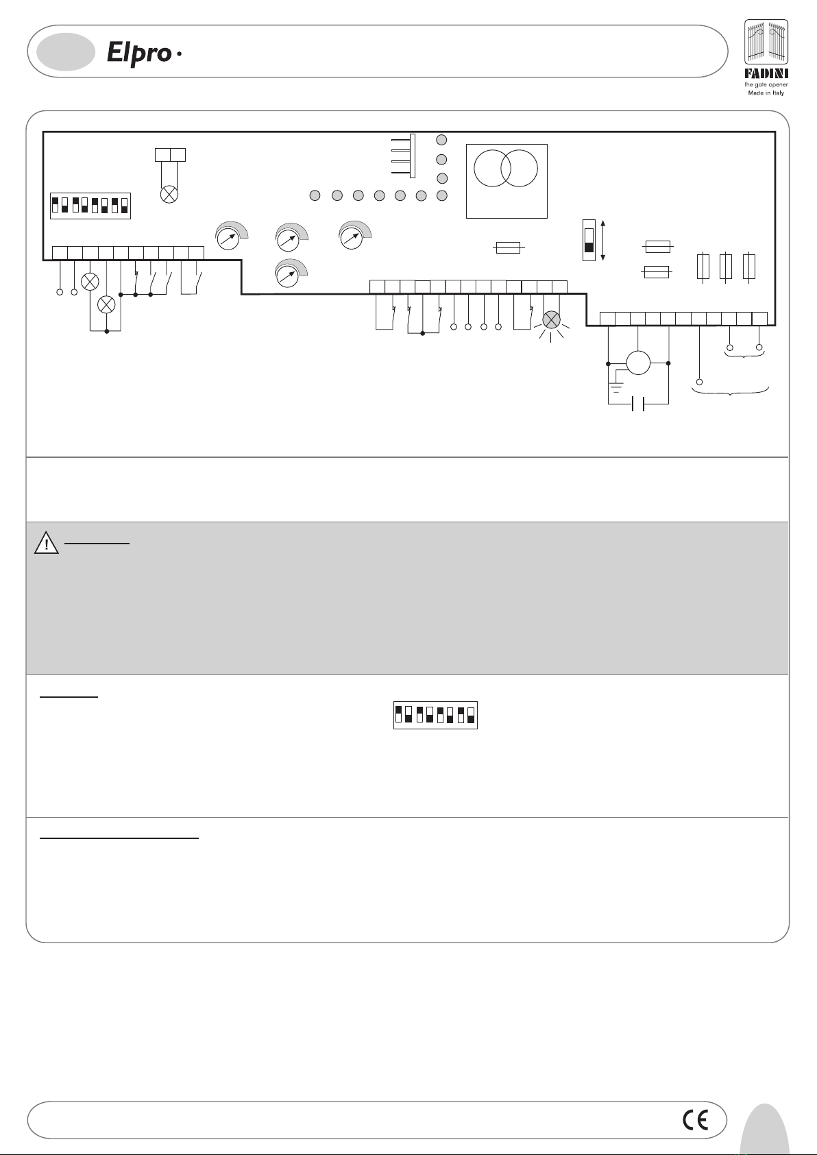
PLEASE NOTE:
- The control panel is fitted inside Mec 200.
- Make sure that the power supply to the electronic programmer is 230V ±10% or 400V ±10%.
- Make sure that the power supply to the Electric Motor is 230V ±10% or 400V ±10%.
- For distances of over 50 metres we recommend using electric cables with bigger sections.
- Fit the mains to the control panel with a 0.03A high performance circuit breaker.
- Use 1.5 mm2section wires for voltage supply, electric motor and flashing lamp. Maximum recommended distance 50 m.Use 1 mm2section wires for
limit switches, photocells, push-buttons/key-switch and accessories.
- Bridge terminals 11 and 12 if no photocells are required.
- Bridge terminals 5 and 6 if no key- or push-button switches are required.
N.W: To fit extra accessories such as lights, CCTV etc. use only solid state relays to prevent damages to the microprocessor.
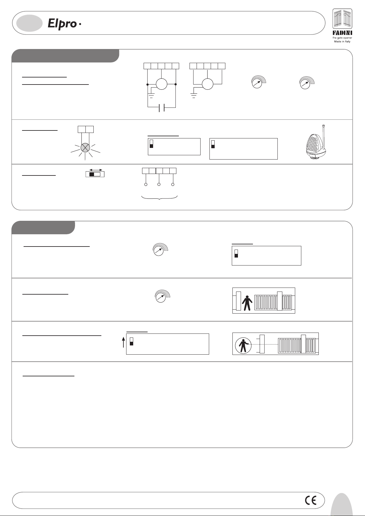
Dip-Switch:
1= ON Photocells. Stop on opening
2= ON Radio. No reversing on opening
3= ON Automatic closing
4= ON Preflashing activated
5= ON Radio.Step by step, stop in between
6= ON Deadman Control (Dip 4=OFF n Dip 3=OFF)
7= ON No light during dwell time
8= OFF. Blank
DIP-SWITCH
145678
2
ON
OFF
3
In case of failure of the panel:
- Make sure that the power supply to the electronic programmer is 230V ±10% or 400V ±10%
- Make sure that the power supply to the Electric Motor is 230V ±10% or 400 V ±10%
- For distances of over 50 metres we recommend using electric cables with bigger sections.
- Check fuses
- Check photocells if contacts are normally closed
- Check all NC contacts
- Check that no voltage drop has occurred from the control panel to the electric motor
DIP-SWITCH ON
OFF
145678
23
L2
L3 L4
L5 L6 L7
400V
F1=8A Mains
F2=8A Mains
F3=8A Mains
F5=1A Flashing
Lamp Protection
F4=630mA
Transformer
Protection
F6=630mA for 24V
protection
TRANSFORMER
MOTOR RUN TIME
from 5 to 150s
DWELL TIME
from 5 to 150s PEDESTRIAN TIME
from 3 to 30s
-
+
-
+
-
+
T3
T2
T1
T
NEUTRAL
S
LIVE
MOTOR
M
U
WV
16µF CAPACITOR for
single-phase application
1410
25
39
24V RADIO
POWER SUPPLY
INDICATION LAMP CLOSE
COMMON
78
6
STOP
CLOSE
OPEN
RADIO CONTACT
FLASHING LAMP
230V 25W max
191816 17 2322
11 12
PHOTOCELL CONTACT
13 1514
LIMIT SWITCH CLOSE
LIMIT SWITCH OPEN
COMMON
24V PHOTOCELL
SUPPLY
20 21
SAFETY SWITCH
25 2624 292827
230V
±10%
50Hz
SINGLE-PHASE
POWER SUPPLY
L9
L8
L1
L10
R
LIVE
230/400V
±10%
50Hz
THREE-PHASE
POWER SUPPLY
INDICATION
LIGHT
24V max 3W
230V
COM.
+24 SPIA
ELECTRIC LOCK
OR 12V AC RELAY FOR 230V
COURTESY LIGHT
-
+
T4
EXT TIME (Electric lock &
Courtesy Light) from 2 to 255s
INDICATION LAMP OPEN
RADIO
PLUG-IN
CARD CONNECTOR

64138
Drwg. No.
LOW VOLTAGE ELECTRICAL CONNECTIONS
®
GB
SINGLE-/THREE-PHASE FOR SLIDING GATE OPERATORS MEC 200
PLUS
70/3
11 12
20 22
21
Safety SwitchRadio Power Supply 12
16 17
Push Button Switch:
Photocell:
18 19
PHOTOCELL
CONTACT POWER SUPPLY 24V
LIGHT
+24V
16 17
1
DIP-SWITCH 1:
ON: Photocells stop gate while opening,
reverse it on closing once obstacle is
removed
OFF: Photocells do not stop gate while
opening, reverse it on closing in
case of an obstacle
Limit switch: 15
COMMON
13 14
LIMIT SWITCH
CLOSE
LIMIT SWITCH
OPEN
Radio Contact: 10
9
COMMON
RADIO
CONTACT
- Open/Close (Standard)
- Travel reversing on pulsing
- Step by step 25
ON: Step by step. Stop in between
OFF: Standard operating mode
ON: Gate is not reversed while opening
OFF: Any pulse reverses the gate
DIP-SWITCH 2 and 5 (NEVER set BOTH of them to ON at the same time):
STOP
COMMON
OPEN
CLOSE
345
INDICATION
LAMP OPEN
48V max 3A
INDICATION
LAMP CLOSE
48V max 3A
78
6
24V 3W Indication Light:
Light ON = Open gate
Light OFF = Closed gate
Flashing (fast) 0.5s = Closing gate
Flashing (normally) 1s = Opening gate
Flashing (slowly) 2s = gate is stopped
Electric lock:
Set the T4 Trimmer Time to the lowest value
The electric lock is excited for 2 seconds Connect a 24VAC Modular Relay
(T4 Trimmer Time from 2s to 255s)
to operate a 230V lamp
Courtesy light:
POWER SUPPLY 24V

7
4138
Drwg. No.
GB
SINGLE-/THREE-PHASE FOR SLIDING GATE OPERATORS MEC 200
PLUS
70/3
®
22 23
230V MAX 25W
230V 400V
Dwell Time
from 5 to 128s
T2
-
+
-
+
-
+
27 22
RT
S
LIVE
2928
230V ±10% 50Hz
SINGLE-PHASE
NEUTRAL
LIVE
400V ±10% 50Hz THREE-PHASE
230/400V ±10% 50Hz
THREE-PHASE MOTOR
M
U
WV
25 2624
230V ±10% 50Hz
SINGLE-PHASE
MOTOR
M
U
WV
25 2624
16µF CAPACITOR
Led Status Indication:
L1 = 230V 50Hz power supply. Alight
L2 = Photocells, if obstructed light goes off
L3 = Open. Alight whenever an Open pulse is given
L4 = Close. Alight whenever a Close pulse is given
L5 = Stop. It goes off on pulsing Stop
L6 = Radio. It goes on by pressing a transmitter button
L7 = Gate Status; it flashes on gate moving
L8 = Limit switch Close; off when gate is closed
L9 = Limit switch Open; off when gate is open
L10= It stays on for a time equal to the time set on T4 Trimmer
Single- (230V) and
Three-phase (400V) Motors:
T1 MOTOR RUN TIME
OPEN / CLOSE
from 5 to 150s
Flashing lamp:
47
DIP-SWITCH 4 and 7:
ON: Pre-flashing
OFF: No pre-flashing
ON: Lamp is not operating during
Dwell Time. Automatic Mode.
OFF: It flashes during Dwell Time .
Automatic Mode.
Power supply:
FADINI
l'apricancello
T2 DWELL TIME
from 5 to 150s
Hold on switched (Deadman) control: DIP-SWITCH 6
6
ON= Deadman Control. Dip-switch 4=OFF
and Dip-switch 3=OFF
OFF= Standard Operations
3
DIP-SWITCH 3
ON= Automatic Closing
OFF= No Automatic. Semi-automatic
closing by pulse
Automatic / Semiautomatic:
Pedestrian Opening:
Trimmer T3 from 3 to 30s.
It can be activated by any pulse (eg. by remote control) superior to 2s
COMMON
ELECTRICAL POWER CONNECTIONS
OPERATING MODES
-
+
Trimmer
T3

La ditta costruttrice si riserva di apportare modifiche al presente libretto senza preavviso
200
182
260 280
110
Via Mantova, 177/A - 37053 Cerea (Verona) Italy - Tel. +39 0442 330422 r.a. - Fax +39 0442 331054
®
s.n.c.
Prima dell'installazione da parte di personale tecnico qualificato, si consiglia di prendere visione del
Libretto Normative di Sicurezza che la Meccanica Fadini mette a disposizione.
Please note that installation must be carried out by qualified technicians following Meccanica Fadini's
Safety Norms Manual.
L'installation doit être effectuée par un technicien qualifié suivant le manuel des Normes de Sécurité
de Meccanica Fadini.
Vor der Montage durch einen Fachmann, wird es empfohlen die Anleitung zur Sicherheitsnormen, die
Meccanica Fadini zur Verfügung stellt, nachzulesen.
Antes de la instalación por el personal técnico calificado, se recomienda leer detenidamente el Folleto
de la Reglamentación de Seguridad que la empresa Meccanica Fadini pone a su disposición.
Voordat de installatie door gekwalificeerd technisch personeel wordt uitgevoerd, wordt geadviseerd
om het boekje met veiligheidsvoorschriften dat Meccanica Fadini ter beschikking stelt door te lezen.
I -
GB -
F -
D -
E -
NL -
VIETATO GETTARE NEI RIFIUTI
MATERIALI NOCIVI PER L’AMBIENTE
Direttiva 2003/108/CE
Smaltimento dei materiali
elettrici ed elettronici
I
DISPOSE OF PROPERLY
ENVIRONMENT-NOXIOUS MATERIALS
2003/108/CE Directive
for waste electrical and
electronic equipments
GB
04-2009
Table of contents
Other fadini Controllers manuals
Popular Controllers manuals by other brands

Savant
Savant SmartLighting SSL-P018 Quick reference guide

Waters
Waters CN6 Operator's guide

Rockwell Automation
Rockwell Automation Allen-Bradley 1756-L72EROMS installation instructions

SOMFY
SOMFY animeo IB 9011809 installation guide

Panasonic
Panasonic FP0H Series Operation manual

Eaton
Eaton COOPER POWER SERIES Installation, operation and maintenance instructions

Vantage Hearth
Vantage Hearth InFusion Controller II Installation

Festo
Festo SEC-ST-48-6-P01 Fitting and installation instructions

CIMCON Lighting
CIMCON Lighting iSLC3100-7P-C-E Installation and commissioning instruction manual

Muchmore
Muchmore Fleta Pro user manual

Wheelock
Wheelock SP-SVC installation instructions

Zamel
Zamel RNK-02 quick guide