fakro ZWMP Parts list manual

Programming and usage instructions
ZWMP weather module
Contents
1 Safety rules ......................................................................................................................................................................2
2 Description of ZWMP weather module ...........................................................................................................................3
3 Installation of ZWMP module ..........................................................................................................................................4
4 Module pro rammin .....................................................................................................................................................5
4.1 Associatin weather module to the Z-Wave network (LEARN MODE function)....................................................6
4.2 Associatin device with ZWMP module (ASSOCIATE function)..........................................................................7
4.2.1 Device operatin by means of “OPEN” and “CLOSE” buttons .......................................................................7
4.3 Device deletin from ZWMP weather module (DELETE function) ........................................................................8
4.4 Return to default settin s of the ZWMP weather module (DEFAULT function)......................................................9
4.5 Removin the ZWMP weather module from the network.........................................................................................9
4.6 Additional functions................................................................................................................................................10
4.6.1 Confi urin the Z-Wave network usin the ZWMP weather module (INCLUDE function)..........................10
4.6.2 Excludin a device from the Z-Wave network usin the ZWMP weather module (EXCLUDE function) ....11
5 Technical parameters......................................................................................................................................................11
6 LED si nallin of di ital inputs and 12V DC power.....................................................................................................12
7 WARRANTY.................................................................................................................................................................12
11.09.21 NC815 1/16 ©2011, FAKRO
GB

1 Safety rules
Read the instructions below carefully before proceeding to device installation so as to
avoid electric shock, injury etc.
CAUTI N!!!
The ZWMP weather module is powered by 230V alternating current. Electric shock
hazard.
When installin the ZWMP module it is crucial to pay close attention to the followin
recommendations:
●Installation should be performed by a qualified individual followin manufacturer's
instructions.
●Connectin the module should be performed with power supply disconnected at all times.
●After unpackin , check module elements for any si ns of mechanical dama e.
●Before connectin the module, make sure that the power supply volta e corresponds with
that provided on the data plate.
●Plastic containers used for packin should be kept out of children's reach as thy may be a
potential source of hazard.
●The ZWMP module should be used for its intended purpose in a reement with its desi n.
The FAKRO Company shall not be held responsible for any consequences resultin from
improper module use.
●Any activities relatin to cleanin , adjustment or disassembly of the module should be
preceded with its disconnection from the mains.
●The module should not be cleaned usin any solvent substances or open stream of water
(do not immerse in water).
●Any module repairs should be carried out by the manufacturer authorised service.
●Electric cables supplyin electricity to the source of power must have suitable area
(2x1mm2). The permissible cable len th for the area specified above is 30 rm.
●The permissible len th of cables plu ed into di ital inputs is 5rm.
●The ZWMP weather module is intended for indoor installation.
11.09.21 NC815 2/16 ©2011, FAKRO

2 Description of ZWMP weather module
The ZWMP weather module (performin the controllin function similarly to the ZWP15 remote
control and ZWK15 keyboard) enables remote control of electronic accessories compatible with the Z-Wave
system, e. . ZWS12 or ZWS30 motors for operatin FAKRO roof windows. This module is equipped with
three di ital inputs (No. 7, 8 and 9 in Figure 1) into which si nals from various external devices can be
plu ed, e. . rain or wind sensors, thermostat, timer switch, EIB system, etc. This module can operate up to 231
devices simultaneously or in roups. The sin le “SEL” button (No. 4 – Figure 1) allows selectin one out of
three channels (No. 2 – Figure 1, channel 1 is inactive) with which controlled devices such as ZWS12 or
ZWS30 motors can be associated. The channels are associated with di ital inputs (No. 7, 8 and 9 – Figure 1)
throu h which devices are operated. Devices associated with:
•channel 2 are operated from di ital input No.2,
•channel 3 are operated from di ital input No.3, etc.
The devices associated with one of the channels can only OPEN or CLOSE after sendin a si nal to its di ital
input. The ZWMP weather module is equipped with two-way ”Z - Wave” communication system. For
communication, the Z-Wave system utilises radio wave frequency of 868,43 Mhz. In Figure 1, there is
presented a eneral view of the ZWMP weather module with description of available buttons and si nals.
11.09.21 NC815 3/16 ©2011, FAKRO
Figure 1: ZWMP weather module
6. Digital input and 12V DC power signaling
(see chapter 6).
7.Z D rain sensor input: COM$-$white,
„-”$-$brown, „+”$-$green.
8. ZWD wind sensor input.
9. Universal digital input, e.g. for thermostat.
10. Screw fixing electronic plate to casing.
11. “CLOSE” button.
1. Fuse 0,315A
2. Active channel signalling.
2.1. Channel 1 signalling
2.2. Channel 2 signalling
2.3. Channel 3 signalling
2.4. Channel 4 signalling
3. “In/Ex” functional button
4. “SELECT” button for changing active
channel.
5. “OPEN” button
10 7
11
12
5
4
3
230VAC
T ANSFO ME
1
In/Ex SEL
OC
234
2 3 4 12V
+
-
8
9
COM
6

3 nstallation of ZWMP module
The ZWMP module should be mounted onto a wall or other permanent element of the buildin by
means of screws driven into cylindrical plu s inserted into openin s drilled in the wall. In order to install the
ZWMP module, it is necessary to:
1. Take off the upper section of the casin .
2. Take out the screws fixin electronic plate to the casin (see Figure 1).
3. Take electronic plate out of the casin .
4. Screw the lower section of the casin to the wall.
5. Screw electronic plate to the lower section of the casin .
6. Make all the necessary electric connections.
7. Remount the upper section of the casin .
11.09.21 NC815 4/16 ©2011, FAKRO
Figure 2: ZWMP weather module casing
12cm
8 cm
5cm
Upper part of module casin
Lower part of module casin

4 Module programming
In order to operate electric FAKRO accessories equipped with the Z-WAVE system by means of
the ZWMP weather module, it is necessary to:
1. Add the device to be operated by means of the module to the “Z-Wave” system – see ZWP15 remote
control and ZWK15, ZWK1 keyboards manuals, chapter “Addin device to the network (INCLUDE
function)” or other controller workin in the Z-Wave system. If the device is already operated with one
of the controllers, proceed to section 2.
2. Add the weather module to the Z-Wave network as a SECONDARY controller, chapter 4.1 (LEARN
MODE function).
and
3. Associate the device with a selected channel in the module (No. 2, Figure 1) specifyin the task to be
performed by it (chapter 4.2, ASSOCIATE function): “O” - open, raise blind, “C” - close, lower blind.
Caution!!!
Every device physically removed from the network (e. . in case of dama ed) needs to be deleted
from the network (Sec. 4.6.2) so as to ensure the optimum communication between devices. Disconnectin a
device without deletin it from the controllers' memory will result in prolon ed reaction time to the commands
sent and accelerated runnin down the batteries of the controller. If it becomes necessary to remove a dama ed
device whose deletin from the memory is impossible, it is advisable to reconfi ure the whole network (all
devices). When relocatin a device within the network (e. . socket module) it is recommended to delete it first
from the network and then, after installin it in a new work place, repeat addin procedure.
11.09.21 NC815 5/16 ©2011, FAKRO

4.1 Associating weather module to the Z-Wave network (LEARN ODE function)
Associatin the weather module (controller) results in its bein cate orized as SECONDARY.
Associatin the module with the network consists in sendin data to it from PRIMARY controller. The
procedure of associatin the module with the network is presented in Fi ure 3. In order to assure the best
possible communication within the network and after each its modification (includin or removin a device):
•associatin another controller with the network should be performed after associatin all devices with
the first controller (“PRIMARY”),
•or performin LEARN MODE a ain on the “SECONDARY” controller already associated with the
network.
*) Pro rammin error results from failure to receive any reply from the device which can be caused by:
•failure to enter LEARN MODE in the ZWMP weather module by pressin the “In/Ex” button three
times until the PRIMARY controller is si nallin its readiness for addin a new device to the network:
•lon distance between the controller and ZWMP module;
•the module is associated with another network and it is necessary to carry out the DEFAULT procedure
first.
11.09.21 NC815 6/16 ©2011, FAKRO
Figure 3: Associating ZWMP module with Z-Wave network
3. Module is si nalin start of
associatin with the network (two
LEDs on as presented in the
drawin for app. 10 sec.).
1.Press “In/Ex” button once on
the PRIMARY controller, e. .
ZWK15 keyboard.
2. Press “In/Ex” button three times in
ZWMP module which is to be added
to the network.
4. After few seconds, the module
is si nalin that associatin with
the network is complete (LEDs on
as presented in the drawin for
app. 2-3 sec.).
5*. Pro rammin error – two LEDs
flashin for app. 2-3 sec.
Primary Secondary Secondary
Secondary Secondary Secondary
6. Associate the device with a
selected pair of buttons on the
controller with which user wishes to
operate the device (ASSOCIATE
function) – see section 4.2.
x1
OC
SelIn/Ex
4321
x3
OC
SelIn/Ex
4321
OC
SelIn/Ex
4321
OC
SelIn/Ex
4321
OC
SelIn/Ex
4321

4.2 Associating device with ZW P module (ASSOCIATE function)
Associatin a device with the ZWMP module which has been already added to the Z-Wave network
enables operatin that device by means of a si nal sent to the di ital input in the module. The procedure of
device associatin is presented in Figure 4.
*) Pro rammin error results from failure to receive any reply form the device and may be caused by:
•failure to press pro rammin button within 10 seconds from the moment module is si nallin its readiness for associatin
a new device with a selected channel;
•lon distance between the module and device bein added;
•the device already belon in to the network other the module with which it is associated. It is necessary to associate the
module with the same network in which the device operates.
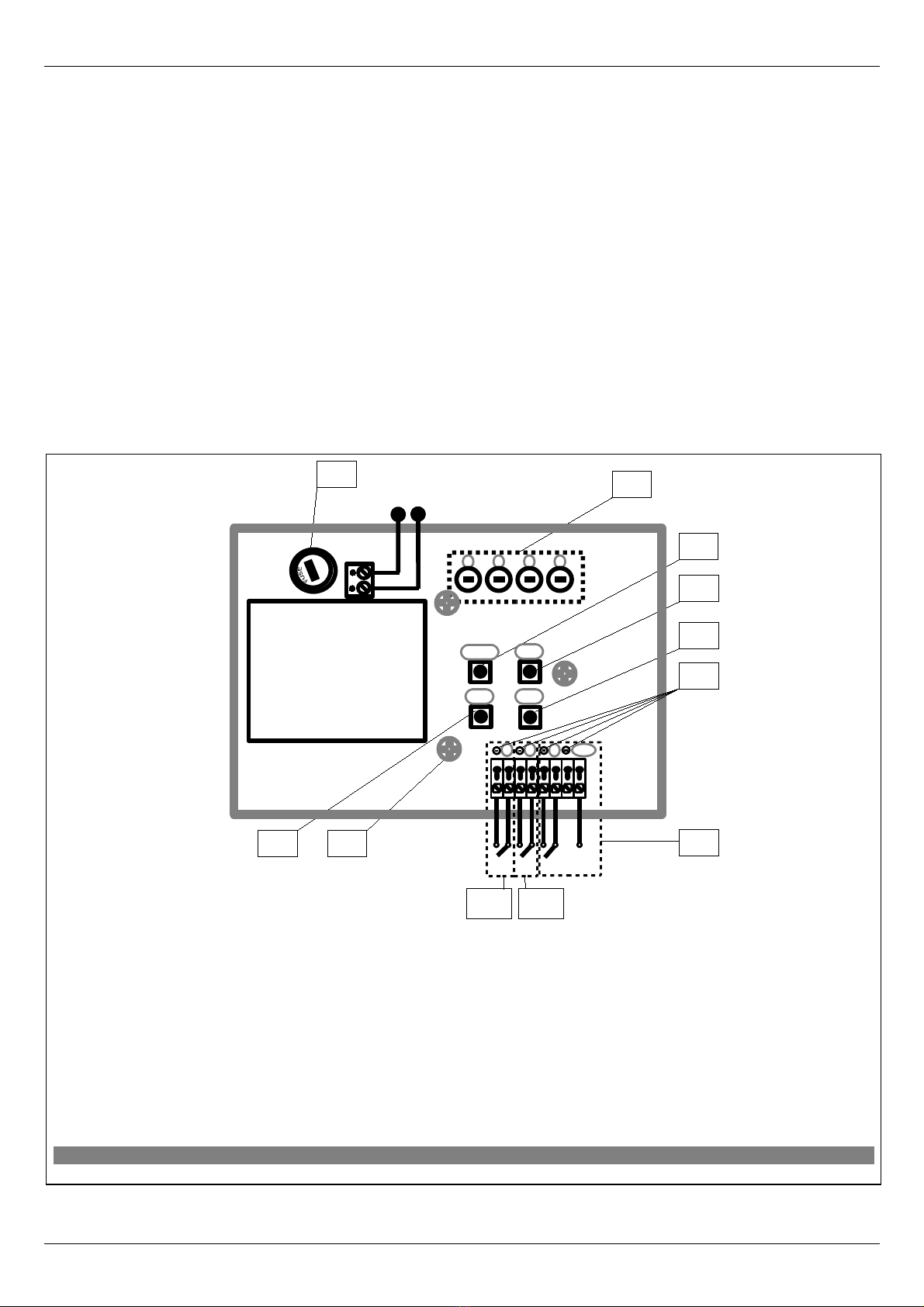
4.2.1 Device operating by means of “ PEN” and “CL SE” buttons
After successful associatin the device with a selected channel, it is necessary to verify its operatin with the use of “O”
or “C” button (No. 5, & 11, Figure 1) Keepin “O” or “C” button pressed:
–lon er (more than 1 sec.) - runs the device for the time the button is pressed;
–momentarily (app. 0.3sec.) – runs the device until it reaches its extreme position, i.e. motor chain or blind folded or unfolded
completely. In order to stop the device, it is necessary to keep the button pressed for lon er than 1 second.
CAUTI N: The ZWMP module does not provide a possibility to operate the device “both ways” (e. . blind lowerin and raisin
from the same di ital input (channel).
11.09.21 NC815 7/16 ©2011, FAKRO
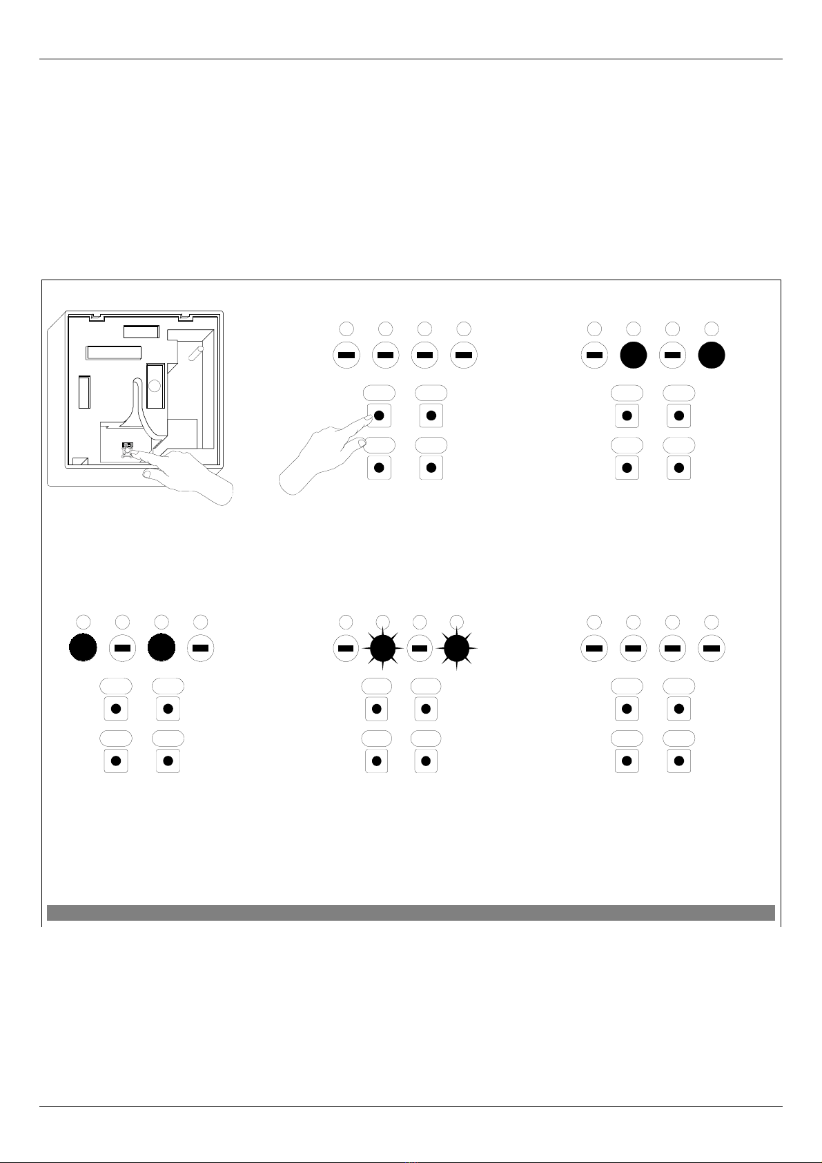
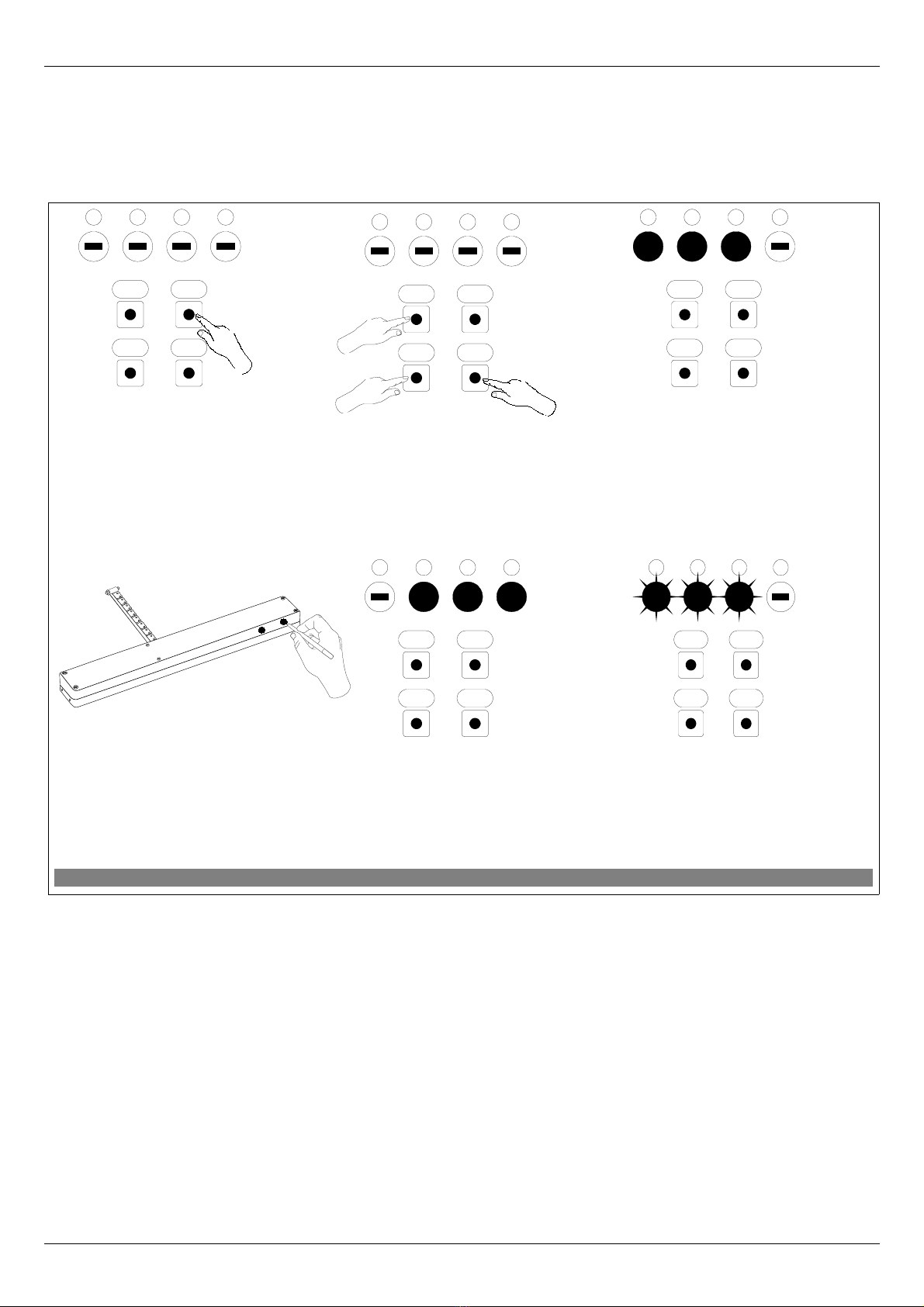
Figure 4: evice associating with selected input In ZWMP module
3. Module is si nallin its
readiness for associatin the
device with a selected channel
(three diodes on for 10 sec.).
5. The module is si nalin that the device
has been associate successfully (three
diodes on for app. 2-3 sec.) In order to
check the correctness of device
operatin proceed to section 4.2.1.
1.Usin SEL button choose a
channel throu h which the device
is to be operated.
6*. Pro rammin error –
LEDs flashin for app. 2-3
sec.
2. Within 1 sec., press:
- “In/Ex” button once and then
- “ ” or “C” buttons, dependin on
how the device is to be operated
after receivin si nal in input reserved
for a selected channel.
4. Press “P” button on the device and
hold it for 0.5 sec. (see Device
Pro rammin Manual).
OC
SelIn/Ex
4321
OC
SelIn/Ex
4321
1
x1
2x1
2
x1 lub
OC
SelIn/Ex
4321
OC
SelIn/Ex
4321
OC
SelIn/Ex
4321
x1

4.3 Device deleting from ZW P weather module (DELETE function)
This function removes from the module's memory the device which has been associated with a
selected channel. It does not remove the device from the “Z-Wave” network. The procedure of deletin the
device from a iven channel is presented in Figure 5.
*) Pro rammin error results from failure to receive any reply from the device and may be caused by:
•failure to press the pro rammin button within 10 seconds from the module si nallin its readiness to
delete the device;
•lon distance between the module and device bein deleted;
•the device belon in to network other than module.
11.09.21 NC815 8/16 ©2011, FAKRO
Figure 5: evice deleting from ZWMP module channel
4. Press “P” button on the device and hold
it for 0.5 sec. (see Device Pro rammin
Manual)
2. Within 1.5 sec., press:
- “In/Ex” button twice and
- “C” or “ ” button, dependin on
how the device has been associated.
6*. Pro rammin error –
LEDs flashin for app. 2-3
sec.).
1. Usin SEL button choose a
channel in the ZWMP module,
throu h which the device to be
deleted is operated.
5. The module is si nalin that the
device has been deleted
successfully (three LEDs on for
app. 2-3 sec.).
3. The module is si nallin
readiness for device deletin
(three LEDs on for 10 sec.).
OC
SelIn/Ex
4321
OC
SelIn/Ex
4321
1
x2
2x1
2
x1 lub
OC
SelIn/Ex
4321
OC
SelIn/Ex
4321
OC
SelIn/Ex
4321
x1

4.4 Return to default settings of the ZW P weather module (DEFAULT function)
Restorin default settin s of the controller leads to the followin information bein deleted from its
memory:
•network, to which the module has been added;
•devices associated with the ZWMP module.
The procedure of restorin default settin s is described in Figure 6.
4.5 Removing the ZW P weather module from the network
Removin the ZWMP module from the network consists in restorin default settin s in this module.
11.09.21 NC815 9/16 ©2011, FAKRO
Figure 6: Restoring default settings in ZWMP controller
1. Within 1.5 sec., press:
- “In/Ex” button twice and then
- SEL button once.
2. The controller is si nalllin that default settin s
have been restored – alternate flashin of internal
and external LEDs for app. 2-3 sec.
OC
SelIn/Ex
4321
1
x2 2x1
OC
SelIn/Ex
4321
OC
SelIn/Ex
4321

4.6 Additional functions
4.6.1 Configuring the Z-Wave network using the ZW P weather module (INCLUDE function).
Addin a device to the “Z-Wave” network is possibly only with the use of PRIMARY controller
(e. . keyboard ZWK15, ZWK1, ZWP15, ZWPTV). The ZWMP module should be associated with the network
as SECONDARY. However, there is a possibility of pro rammin the module for the network as PRIMARY.
The procedure of device addin to the network with the use of the ZWMP module is presented in Figure 7.
*) Pro rammin error results from the fact of not receivin any response from the device and may be caused
by:
•failure to press the pro rammin button within 10 seconds from the module si nallin its readiness for
addin the device to the network;
•lon distance between the module and the device bein added;
•the module has been earlier associated with the network as SECONDARY – it is necessary to perform
DEFAULT procedure.
11.09.21 NC815 10/16 ©2011, FAKRO
Figure 7: Removing device from the Z-Wave network using ZWMP weather module
4. The controller is si nalin that the
device has been successfully
associated with the network (two
LEDs on for app. 2-3 sec.). For
operatin accessories with the use of
the module, proceed to section 4.2.
5*. Pro rammin error – LEDs
flashin for app. 2-3 sec.
2. The controller is si nalin its
readiness for addin a new device
to the network (two external
LEDs on for 10 sec.).
3. Press “P” button on the device and
hold it for 0.5 sec. (see Device
Pro rammin Manual).
1. Press “In/Ex” button once.
OC
SelIn/Ex
4321
x1
OC
SelIn/Ex
4321
OC
SelIn/Ex
4321
OC
SelIn/Ex
4321
x1

4.6.2 Excluding a device from the Z-Wave network using the ZW P weather module (EXCLUDE
function)
Excludin a device from the “Z-Wave” network is possible only with the use of a PRIMARY
controller (e. . keyboard ZWK15, ZWK1, ZWP15, ZWPTV). If the ZWMP module in the Z-Wave network is
marked as PRIMARY (network confi uration as per section 4.6.1), then devices can be excluded only usin
that module. The procedure of device excludin from the network with the use of the ZWMP module is
presented in Figure 8.
*) Pro rammin error results from the fact of not receivin any response from the device and may be caused
by:
•failure to press the pro rammin button within 10 seconds from the module si nallin its readiness to
delete the device;
•the device belon in to network other than module.
5 Technical parameters
Technical parameters
Power 230VAC
Working temperature (+5OC) to (40OC)
Working range to 40 [m]
Working frequency 868,43 MHz
Maximum cable length of the device plugged
into digital or analogue input 5 rm
11.09.21 NC815 11/16 ©2011, FAKRO
Figure 8: Excluding device from the Z-Wave network with the use of ZWMP weather module.
4. The controller is si nalin that the
device has been successfully excluded
form the network (two external LEDs
on for app. 2-3 sec.).
5*. Pro rammin error – two
middle LEDs flashin for app. 2-3
sec.
2. The controller is si nalin
readiness for excludin the device
from the network (two middle
LEDs on for 10 sec.).
3. Press “P” button on the device and
hold it for 0.5 sec. (see Device
Pro rammin Manual).
1. Within 1 sec, press “In/Ex”
button twice.
OC
SelIn/Ex
4321
OC
SelIn/Ex
4321
x2
OC
SelIn/Ex
4321
OC
SelIn/Ex
4321
x1

6 LED signalling of digital inputs and 12V DC power
The LEDs (Figure 1, No. 6) by di ital inputs inform about activation of the connected sensors.
LED by input:
–No. 2 (Figure 1, No. 9) is on when short across input contacts occurs;
–No. 3 (Figure 1, No. 8) is on when wind speed exceeds the value activatin the input (default 30km/h );
–No. 4 (Figure 1, No. 7) is on when short across input contacts occurs.
–12VDC (Figure 1, No. 7) is off if the connected rain sensor is faulty (short circuit).
7 WARRANTY
The manufacturer uarantees correct device functionin . It also undertakes to repair
or replace the device if its defects result from material or structural faults. The warranty period
is 24 months from the purchase date, fulfillin the followin conditions:
●Installation has been performed by an authorised individual, as per manufacturer
recommendations.
●Seals remain intact and no unauthorised structural chan es have been made.
●The device has been used in accordance with its intended use as per user manual.
●Dama e is not a result of improperly made electrical system or atmospheric phenomena.
●The manufacturer is not liable for dama e which occurred as a result of improper use or
mechanical dama e.
In case of failure, the device must be submitted for repair with a Warranty Card. Defects
revealed within the warranty period will be removed free of char e no lon er than 14 days after
acceptin the product for repair. Warranty and post-warranty repairs are performed by the
manufacturer i.e. FAKRO PP. Sp. z o.o..
Quality certificate:
Device
Model............................................................................................................................................
Serial number...............................................................................................................................
Seller.............................................................................................................................................
Address...........................................................................................................................................
Date of purchase.............................................................................................................................
...............................................................................................................
Si nature (stamp) of installin person
11.09.21 NC815 12/16 ©2011, FAKRO

11.09.21 NC815 13/16 ©2011, FAKRO

11.09.21 NC815 14/16 ©2011, FAKRO

11.09.21 NC815 15/16 ©2011, FAKRO
Table of contents
Other fakro Control Unit manuals
Popular Control Unit manuals by other brands

Bodine
Bodine PACESETTER 2999 Instructions for installation and operation

Samson
Samson EB 8061 EN TRANSLATION OF ORIGINAL INSTRUCTIONS

Asco
Asco 8003P Series Installation & maintenance instructions

Galvin
Galvin Safe-Cell 50101C Product installation guideline

ChemValve-Schmid
ChemValve-Schmid SwissValve CST-K Maintenance Instruction

Crestron
Crestron CWD6671 Operation guide