Falcon T Series User manual

H
V
B
Q
S
T
R
T Series Service Manual
Extra Heavy Duty, Grade 1 Cylindrical Lever Lock

T-Series Service Manual ii
Table of Contents
Table of Contents
Introduction ............................................................... iii
Lock Assembly Index................................................. 1
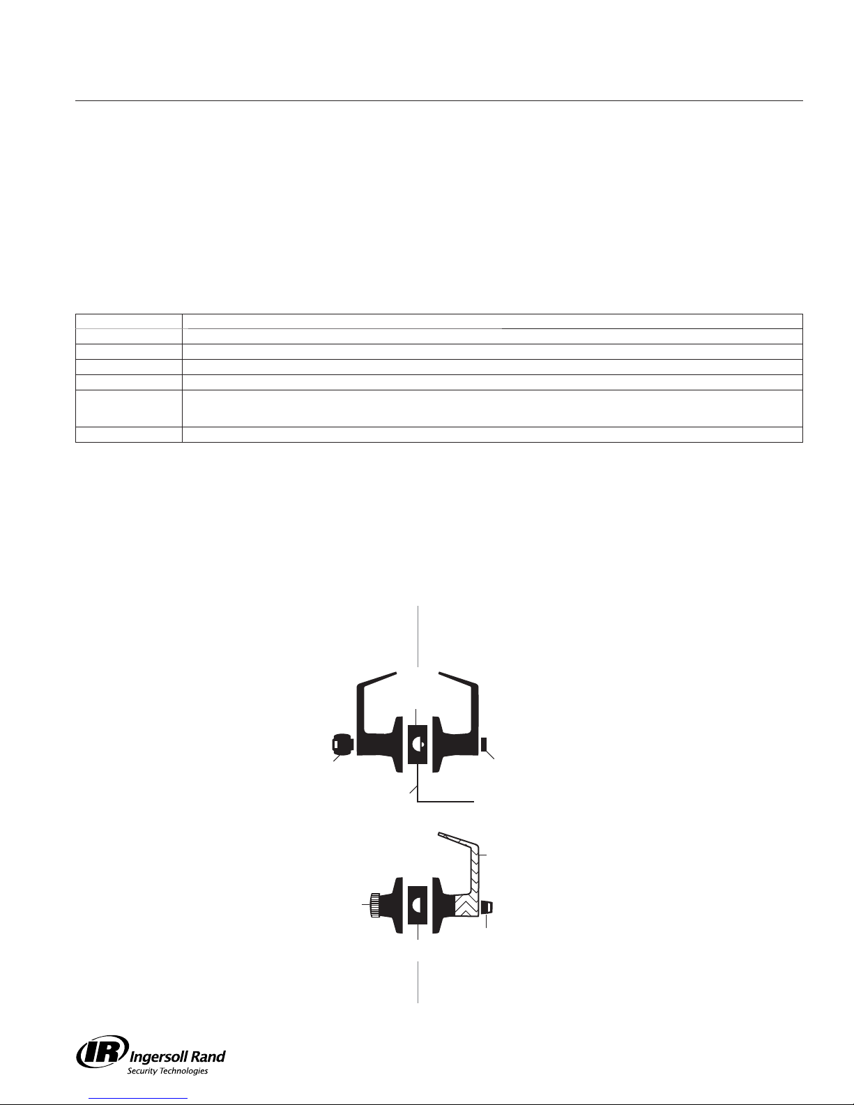
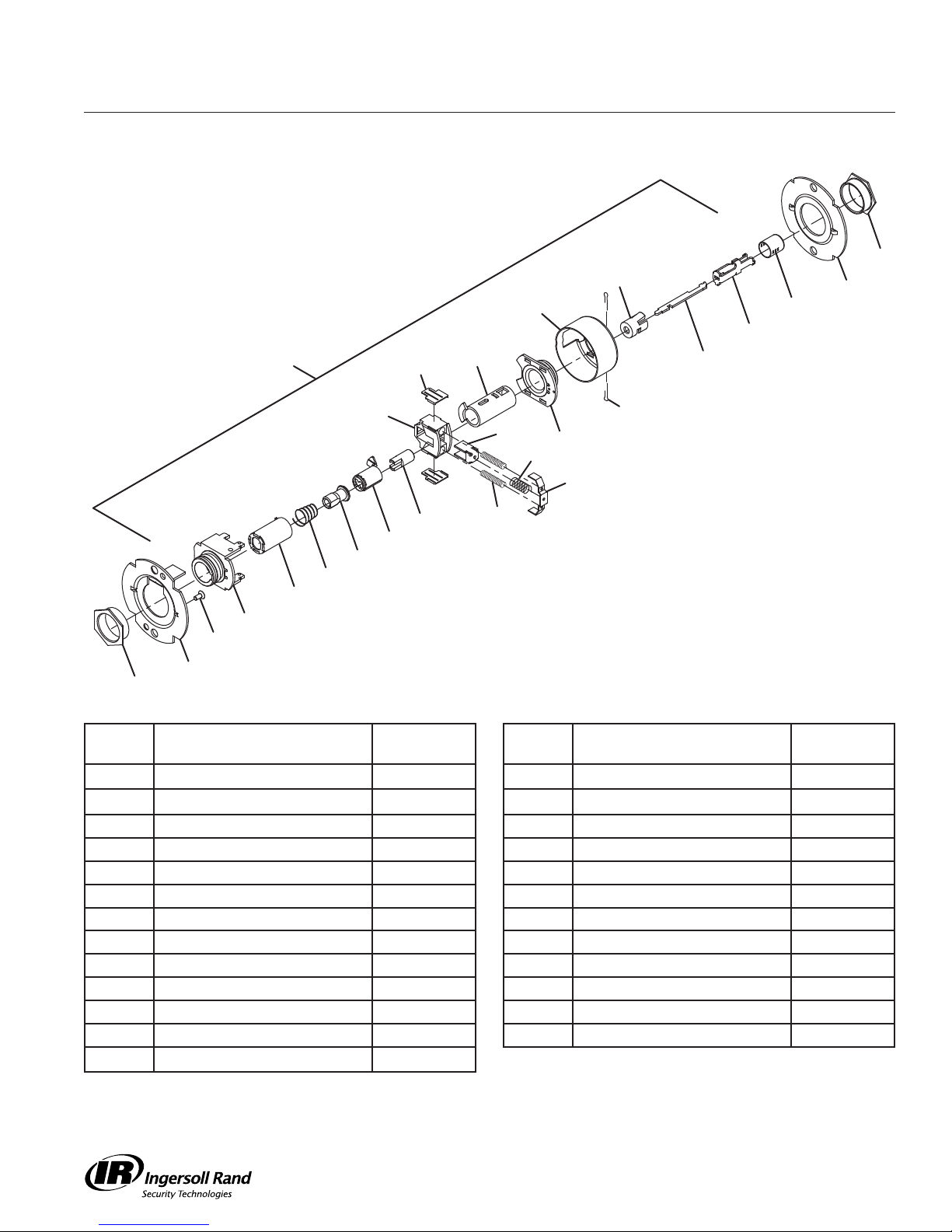
Chassis Assemblies................................................... 3
Trim Assemblies....................................................... 27
Standard Cylinders .................................................. 41
Falcon Complete Standard Cylinders ..................... 41
Standard Cylinder Options...................................... 41
Standard Cylinder Tailpieces................................... 41
Cylinders................................................................... 41
Competitor Keyway Compatibility............................ 42
IC Cylinders .............................................................. 42
Falcon Complete IC Cylinders ................................ 42
IC Cylinder Options................................................. 43
IC Cylinder Tailpieces.............................................. 43
Competitor IC Compatibility .................................... 43
Inserts and Spindles ................................................ 44
Inside Inserts and Spindles..................................... 44
Outside Inserts and Spindles.................................. 45
Levers........................................................................ 46
Closed Levers ......................................................... 46
Open Levers............................................................ 46
SFIC/IC Levers........................................................ 47
Spring Cage Replacement Kits............................... 47
Latches and Accessories ........................................ 48
Levers........................................................................ 48
Grade 1 Latches...................................................... 48
Grade 2 Latches...................................................... 48
Accessories............................................................. 49
Strikes and Dust Boxes ........................................... 50
Strikes ..................................................................... 50
Dust Boxes.............................................................. 50
Preparation and Installation.................................... 51
Installation Template ............................................... 51
Tailpiece Installation................................................ 51
Installation Instructions ........................................... 52
Spring Cage Replacement Installation.................... 58
Warranty.................................................................... 59

iii T-Series Service Manual
Introduction
Introduction
This manual contains a complete listing of T-Series (Grade 1) cylindrical lock parts and assemblies manufactured by
the Falcon Lock Company. This edition lists components of T-Series locks manufactured after July 2007.
Exploded views of each lock chassis and trim assemblies are provided with an accompanying chart to identify parts
for replacement purposes. In addition, this manual provides general cylinder information, many auxiliary components
of the T-Series cylindrical locks and installation instructions.
Standard Features*
Certifications ANSI A156 .2, Series 4000, Grade 1, UL Listed for 3-hour fire door.
Latch 156” x 256M”, Square corner faceplate, 1” housing diameter, 56O” throw.
Strike 56M” x 4(6”, ANSI, Square corner, no box.
Backset 26M”
Cylinder 6-Pin solid brass, keyed 5-pin, Falcon G keyway, keyed different (KD)
Door Range 16M” – 256” standard
Keys Two nickel silver cut keys per lock, keyed 5-pin, Falcon G keyway
* Locks are furnished with standard features unless otherwise specified.
Lock Assembly Drawing Index
The Lock Assembly Drawing Index provides visual representations and textual descriptions of available functions.
Page numbers for full trim and chassis drawings are referenced.
Outside Inside
Key Push button
Electrified
Deadlatch
Springlatch
Turn/push button
Knurled Knob
Fixed Lever

T-Series Service Manual 1
Lock Assembly Index
Function ANSI A156.2, 1996, Series 4000, Grade 1 Trim Chassis
FALCON ANSI DESCRIPTION OUTSIDE FUNCTION INSIDE FUNCTION
T101 F75 Passage/Closet
Latch
Lever is always unlocked. Lever is always unlocked
and is always free for
immediate egress.
27 3
T291 Privacy Hospital
Lock
Unlocked from outside
by turning emergency
turn-button.
Push-button locks
outside lever. Turning
inside lever or closing
door releases button.
Inside lever is always
free for immediate egress.
28 4
T301 F76 Privacy Lock Can be opened from
outside with small
screwdriver or
emergency release tool.
Push-button locks
outside lever. Turning
inside lever or closing
door releases button.
Inside lever is always
free for immediate egress.
29 4
T351 Closet Lock Can be locked with key. Knurled knob free for
immediate egress unless
outside lever locked with
key.
30 5
6 (IC)
T381 F88 Classroom
Security Lock
Outside lever locked or
unlocked by key in either
lever.
Key locks or unlocks
outside lever. Inside lever
is always unlocked and is
always free for
immediate egress.
31 7
8 (IC)
T411 F87 Asylum Lock Lever is fixed. Entrance
by key only.
Lever is fixed. Exit by
key only.
32 9
10 (IC)
T501 F82 Entry Lock Lever is
unlocked with key
when push-button
is pushed.
Push-button locks
outside lever. Turning
inside lever releases
button. Inside lever is
always free for immediate
egress.
33 11
12 (IC)
T511 F109 Entry/Office Lock Key retracts latch when
button pushed and
turned. Lever is
unlocked with key
when push-button
is pushed.
Turn/push-button: pushing
and turning button locks
outside lever until manually
unlocked. Push-button:
pushing button locks
outside lever until unlocked
by turning inside lever.
Inside always free for
immediate egress.
34 13
14 (IC)
NOTE: Any function with deadlatch locks latchbolt when door is closed.
Lock Assembly Index

2T-Series Service Manual
Lock Assembly Index
Function ANSI A156.2, 1996, Series 4000, Grade 1 Trim Chassis
FALCON ANSI DESCRIPTION OUTSIDE FUNCTION INSIDE FUNCTION
T521 F81 Office Lock Key retracts latch when
button turned.
Turning button locks
outside lever until manually
unlocked. Inside always
free for immediate
egress.
35 15
16 (IC)
T561 F84 Classroom Lock Outside lever locked or
unlocked by key.
Inside lever is always
unlocked and always
free for immediate
egress.
36 17
18 (IC)
T571 F90 Dormitory Lock Locked or unlocked
by key. When locked
by key it can only be
unlocked by key.
Push-button locks
outside lever. Turning
lever or closing door
releases button.
Inside lever is always
unlocked and is always
free for immediate
egress.
37 19
20 (IC)
T581 F86 Storeroom Lock Lever is fixed. Entrance
by key only.
Inside lever is always
unlocked and is always
free for immediate
egress.
38 21
22 (IC)
T851 Storeroom Lock
(Electrified – Fail
Safe)
Lever is continuously
locked electrically.
Unlocked by switch or
power failure. When
locked, key retracts latch.
Inside lever is always
unlocked and is always
free for immediate
egress.
39 23
24 (IC)
T881 Storeroom Lock
(Electrified – Fail
Secure)
Lever is continuously
locked mechanically until
unlocked by electric
current. When locked,
key retracts latch.
Inside lever is always
unlocked and is always
free for immediate
egress.
40 25
26 (IC)
NOTE: Any function with deadlatch locks latchbolt when door is closed.

T-Series Service Manual 3
Chassis Assemblies
T101
Passage Latchset
6
6
8 (2)
7
9 (2)
10
13 (2)
12
2
14
11
2
1
3
5
4
Call Out
Number Description Part Number
Call Out
Number Description Part Number
1 Chassis Assembly, T101 A30761-000-00 8 Retractor Insert (2) 022986-001-50
2 Flanged Nut (2) 030726-000-30 9 Retractor Spring (2) 022108-001-60
3 Outer Mounting Plate 030712-001-30 10 Retractor Spring Retainer 022112-000-30
4#8-32 x 6” Self Tap Screw 031533-006-30 11 Hub and Plate Assembly A30747-000-00
5 Hub and Housing Assembly A30746-000-00 12 Housing Case 022114-000-30
6 Spindle 030733-000-55 13 Cotter Pin (2) 002893-000-60
7 Retractor 022106-002-55 14 Inner Mounting Plate 030712-000-30

4T-Series Service Manual
Chassis Assemblies
T291/T301
Privacy Hospital Lock
8 (2)
7
11
623
13 (2)
1
2
15
17
18
19
16
3
5
22
24
25
2
14
12
10
9 (2)
21
20
4
Call Out
Number Description Part Number
Call Out
Number Description Part Number
1 Chassis Assembly, T291/T301 A30765-000-00 14 Inner Mounting Plate 030712-000-30
2 Flanged Nut (2) 030726-000-30 15 Spindle, 1 Ear, Outer 030732-005-30
3 Outer Mounting Plate 030712-001-30 16 Clutch Spring 030709-000-60
4#8-32 x 6” Self Tap Screw 031533-006-30 17 Clutch Driver 030716-001-30
5 Hub and Housing Assembly A30746-000-00 18 Key Spindle STD 030718-000-30
6 Spindle 030733-000-55 19 Push Actuator 030711-000-30
7 Retractor 022106-002-55 20 Slide Catch 022105-000-30
8 Retractor Insert (2) 022986-001-50 21 Slide Catch Spring 012107-001-60
9 Retractor Spring (2) 022108-001-60 22 Push Button Sleeve 022134-000-50
10 Retractor Spring Retainer 022112-000-30 23 Dogging Bar 030722-000-30
11 Hub and Plate Assembly A30747-000-00 24 Push/Turn Button Mount 030731-000-30
12 Housing Case 022114-000-30 25 Push Button Cap 030728-000*
13 Cotter Pin (2) 002893-000-60

T-Series Service Manual 5
Chassis Assemblies
T351
Closet Lock
26
6
8 (2)
7
9 (2)
10
13 (2)
12
2
14
11
2
3
5
1
4
Call Out
Number Description Part Number
Call Out
Number Description Part Number
1 Chassis Assembly, T351/T561 A30758-000-00 9 Retractor Spring (2) 022108-001-60
2 Flanged Nut (2) 030726-000-30 10 Retractor Spring Retainer 022112-000-30
3 Outer Mounting Plate 030712-001-30 11 Hub and Plate Assembly A30747-000-00
4#8-32 x 6” Self Tap Screw 031533-006-30 12 Housing Case 022114-000-30
5 Hub and Housing Assembly A30746-000-00 13 Cotter Pin (2) 002893-000-60
6 Spindle 030733-000-55 14 Inner Mounting Plate 030712-000-30
7 Retractor 022106-002-55 26 Key Spindle Assembly, STD A30780-000-30
8 Retractor Insert (2) 022986-001-50

6T-Series Service Manual
Chassis Assemblies
T351
Closet Lock – IC
27
6
8 (2)
7
9 (2)
10
13 (2)
12
2
14
11
2
3
5
1
4
Call Out
Number Description Part Number
Call Out
Number Description Part Number
1 Chassis Assembly, T351/T561-
IC
A30758-001-00 9 Retractor Spring (2) 022108-001-60
2 Flanged Nut (2) 030726-000-30 10 Retractor Spring Retainer 022112-000-30
3 Outer Mounting Plate 030712-001-30 11 Hub and Plate Assembly A30747-000-00
4#8-32 x 6” Self Tap Screw 031533-006-30 12 Housing Case 022114-000-30
5 Hub and Housing Assembly A30746-000-00 13 Cotter Pin (2) 002893-000-60
6 Spindle 030733-000-55 14 Inner Mounting Plate 030712-000-30
7 Retractor 022106-002-55 27 Key Spindle Assembly, IC A30780-001-30
8 Retractor Insert (2) 022986-001-50

T-Series Service Manual 7
Chassis Assemblies
T381
Classroom Security Lock
30
23
5
15
17
18
19
16
8 (2)
7
9 (2)
10
2
14
13 (2)
12
11
28
1
4
Call Out
Number Description Part Number
Call Out
Number Description Part Number
1 Chassis Assembly, T381 A30767-000-00 12 Housing Case 022114-000-30
2 Flanged Nut (2) 030726-000-30 13 Cotter Pin (2) 002893-000-60
3 Outer Mounting Plate 030712-001-30 14 Inner Mounting Plate 030712-000-30
4#8-32 x 6” Self Tap Screw 031533-006-30 15 Spindle, 1 Ear, Outer 030732-005-30
5 Hub and Housing Assembly A30746-000-00 16 Clutch Spring 030709-000-60
7 Retractor 022106-002-55 17 Clutch Driver 030716-001-30
8 Retractor Insert (2) 022986-001-50 18 Key Spindle STD 030718-000-30
9 Retractor Spring (2) 022108-001-60 19 Push Actuator 030711-000-30
10 Retractor Spring Retainer 022112-000-30 28 IS Key Spindle Assembly, STD A30913-000-00
11 Hub and Plate Assembly A30747-000-00 30 Connecting Rod 030734-000-30

8T-Series Service Manual
Chassis Assemblies
T381
Classroom Security Lock – IC
30
23
5
15
17
31
19
16
8 (2)
7
9 (2)
10
2
14
13 (2)
12
11
29
1
4
Call Out
Number Description Part Number
Call Out
Number Description Part Number
1 Chassis Assembly, T381 A30767-001-00 12 Housing Case 022114-000-30
2 Flanged Nut (2) 030726-000-30 13 Cotter Pin (2) 002893-000-60
3 Outer Mounting Plate 030712-001-30 14 Inner Mounting Plate 030712-000-30
4#8-32 x 6” Self Tap Screw 031533-006-30 15 Spindle, 1 Ear, Outer 030732-005-30
5 Hub and Housing Assembly A30746-000-00 16 Clutch Spring 030709-000-60
7 Retractor 022106-002-55 17 Clutch Driver 030716-001-30
8 Retractor Insert (2) 022986-001-50 19 Push Actuator 030711-000-30
9 Retractor Spring (2) 022108-001-60 29 IS Key Spindle Assembly, IC A30913-001-00
10 Retractor Spring Retainer 022112-000-30 30 Connecting Rod 030734-000-30
11 Hub and Plate Assembly A30747-000-00 31 Key Spindle, IC 030718-001-30

T-Series Service Manual 9
Chassis Assemblies
T411
Asylum Lock
32
32
8 (2)
7
9 (2)
10
13 (2)
2
14
11
2
3
5
12
1
4
Call Out
Number Description Part Number
Call Out
Number Description Part Number
1 Chassis Assembly, T411 A30769-000-00 9 Retractor Spring (2) 022108-001-60
2 Flanged Nut (2) 030726-000-30 10 Retractor Spring Retainer 022112-000-30
3 Outer Mounting Plate 030712-001-30 11 Hub and Plate Assembly A30747-000-00
4#8-32 x 6” Self Tap Screw 031533-006-30 12 Housing Case 022114-000-30
5 Hub and Housing Assembly A30746-000-00 13 Cotter Pin (2) 002893-000-60
7 Retractor 022106-002-55 14 Inner Mounting Plate 030712-000-30
8 Retractor Insert (2) 022986-001-50 32 Spindle, 2 Ear, STD 030732-000-30

10 T-Series Service Manual
Chassis Assemblies
T411
Asylum Lock – IC
33
33
8 (2)
7
9 (2)
10
13 (2)
2
14
11
2
3
5
12
1
4
Call Out
Number Description Part Number
Call Out
Number Description Part Number
1 Chassis Assembly, T411-IC A30769-001-00 9 Retractor Spring (2) 022108-001-60
2 Flanged Nut (2) 030726-000-30 10 Retractor Spring Retainer 022112-000-30
3 Outer Mounting Plate 030712-001-30 11 Hub and Plate Assembly A30747-000-00
4#8-32 x 6” Self Tap Screw 031533-006-30 12 Housing Case 022114-000-30
5 Hub and Housing Assembly A30746-000-00 13 Cotter Pin (2) 002893-000-60
7 Retractor 022106-002-55 14 Inner Mounting Plate 030712-000-30
8 Retractor Insert (2) 022986-001-50 33 Spindle, 2 Ear, IC 030732-001-30

T-Series Service Manual 11
Chassis Assemblies
T501
Entry Lock
8 (2)
7
11
623
13 (2)
1
2
15
17
18
19
16
3
5
22
24
25
2
14
12
10
9 (2)
21
34
4
Call Out
Number Description Part Number
Call Out
Number Description Part Number
1 Chassis Assembly, T501 A30773-000-00 14 Inner Mounting Plate 030712-000-30
2 Flanged Nut (2) 030726-000-30 15 Spindle, 1 Ear, Outer 030732-005-30
3 Outer Mounting Plate 030712-001-30 16 Clutch Spring 030709-000-60
4#8-32 x 6” Self Tap Screw 031533-006-30 17 Clutch Driver 030716-001-30
5 Hub and Housing Assembly A30746-000-00 18 Key Spindle STD 030718-000-30
6 Spindle 030733-000-55 19 Push Actuator 030711-000-30
7 Retractor 022106-002-55 21 Slide Catch Spring 012107-001-60
8 Retractor Insert (2) 022986-001-50 22 Push Button Sleeve 022134-000-50
9 Retractor Spring (2) 022108-001-60 23 Dogging Bar 030722-000-30
10 Retractor Spring Retainer 022112-000-30 24 Push/Turn Button Mount 030731-000-30
11 Hub and Plate Assembly A30747-000-00 25 Push Button Cap 030728-000*
12 Housing Case 022114-000-30 34 Short Slide Catch 022104-000-30
13 Cotter Pin (2) 002893-000-60

12 T-Series Service Manual
Chassis Assemblies
T501
Entry Lock – IC
8 (2)
7
11
623
13 (2)
1
2
15
17
31
19
16
3
5
22
24
25
2
14
12
10
9 (2)
21
34
4
Call Out
Number Description Part Number
Call Out
Number Description Part Number
1 Chassis Assembly, T501-IC A30773-001-00 14 Inner Mounting Plate 030712-000-30
2 Flanged Nut (2) 030726-000-30 15 Spindle, 1 Ear, Outer 030732-005-30
3 Outer Mounting Plate 030712-001-30 16 Clutch Spring 030709-000-60
4#8-32 x 6” Self Tap Screw 031533-006-30 17 Clutch Driver 030716-001-30
5 Hub and Housing Assembly A30746-000-00 19 Push Actuator 030711-000-30
6 Spindle 030733-000-55 21 Slide Catch Spring 012107-001-60
7 Retractor 022106-002-55 22 Push Button Sleeve 022134-000-50
8 Retractor Insert (2) 022986-001-50 23 Dogging Bar 030722-000-30
9 Retractor Spring (2) 022108-001-60 24 Push/Turn Button Mount 030731-000-30
10 Retractor Spring Retainer 022112-000-30 25 Push Button Cap 030728-000*
11 Hub and Plate Assembly A30747-000-00 31 Key Spindle, IC 030718-001-30
12 Housing Case 022114-000-30 34 Short Slide Catch 022104-000-30
13 Cotter Pin (2) 002893-000-60

T-Series Service Manual 13
Chassis Assemblies
T511
Entry/Office Lock
36
8 (2)
7
11
623
13 (2)
1
2
15
17
18
19
16
3
5
35
24
2
14
12
10
9 (2)
21
34
4
Call Out
Number Description Part Number
Call Out
Number Description Part Number
1 Chassis Assembly, T511 A30756-000-00 14 Inner Mounting Plate 030712-000-30
2 Flanged Nut (2) 030726-000-30 15 Spindle, 1 Ear, Outer 030732-005-30
3 Outer Mounting Plate 030712-001-30 16 Clutch Spring 030709-000-60
4#8-32 x 6” Self Tap Screw 031533-006-30 17 Clutch Driver 030716-001-30
5 Hub and Housing Assembly A30746-000-00 18 Key Spindle STD 030718-000-30
6 Spindle 030733-000-55 19 Push Actuator 030711-000-30
7 Retractor 022106-002-55 21 Slide Catch Spring 012107-001-60
8 Retractor Insert (2) 022986-001-50 23 Dogging Bar 030722-000-30
9 Retractor Spring (2) 022108-001-60 24 Push/Turn Button Mount 030731-000-30
10 Retractor Spring Retainer 022112-000-30 34 Short Slide Catch 022104-000-30
11 Hub and Plate Assembly A30747-000-00 35 Turn Button Sleeve 022133-000-50
12 Housing Case 022114-000-30 36 Turn Button Cap 030727-000*
13 Cotter Pin (2) 002893-000-60

14 T-Series Service Manual
Chassis Assemblies
T511
Entry/Office Lock – IC
36
8 (2)
7
11
623
13 (2)
1
2
15
17
31
19
16
3
5
35
24
2
14
12
10
9 (2)
21
34
4
Call Out
Number Description Part Number
Call Out
Number Description Part Number
1 Chassis Assembly, T511-IC A30756-001-00 14 Inner Mounting Plate 030712-000-30
2 Flanged Nut (2) 030726-000-30 15 Spindle, 1 Ear, Outer 030732-005-30
3 Outer Mounting Plate 030712-001-30 16 Clutch Spring 030709-000-60
4#8-32 x 6” Self Tap Screw 031533-006-30 17 Clutch Driver 030716-001-30
5 Hub and Housing Assembly A30746-000-00 19 Push Actuator 030711-000-30
6 Spindle 030733-000-55 21 Slide Catch Spring 012107-001-60
7 Retractor 022106-002-55 23 Dogging Bar 030722-000-30
8 Retractor Insert (2) 022986-001-50 24 Push/Turn Button Mount 030731-000-30
9 Retractor Spring (2) 022108-001-60 31 Key Spindle, IC 030718-001-30
10 Retractor Spring Retainer 022112-000-30 34 Short Slide Catch 022104-000-30
11 Hub and Plate Assembly A30747-000-00 35 Turn Button Sleeve 022133-000-50
12 Housing Case 022114-000-30 36 Turn Button Cap 030727-000*
13 Cotter Pin (2) 002893-000-60

T-Series Service Manual 15
Chassis Assemblies
T521
Office Lock
8 (2)
7
9 (2)
10
36
11
623
13 (2)
1
2
15
17
18
19
16
3
5
35
24
2
14
12
4
Call Out
Number Description Part Number
Call Out
Number Description Part Number
1 Chassis Assembly, T521 A30748-000-00 13 Cotter Pin (2) 002893-000-60
2 Flanged Nut (2) 030726-000-30 14 Inner Mounting Plate 030712-000-30
3 Outer Mounting Plate 030712-001-30 15 Spindle, 1 Ear, Outer 030732-005-30
4#8-32 x 6” Self Tap Screw 031533-006-30 16 Clutch Spring 030709-000-60
5 Hub and Housing Assembly A30746-000-00 17 Clutch Driver 030716-001-30
6 Spindle 030733-000-55 18 Key Spindle, STD 030718-000-30
7 Retractor 022106-002-55 19 Push Actuator 030711-000-30
8 Retractor Insert (2) 022986-001-50 23 Dogging Bar 030722-000-30
9 Retractor Spring (2) 022108-001-60 24 Push/Turn Button Mount 030731-000-30
10 Retractor Spring Retainer 022112-000-30 35 Turn Button Sleeve 022133-000-50
11 Hub and Plate Assembly A30747-000-00 36 Turn Button Cap 030727-000*
12 Housing Case 022114-000-30

16 T-Series Service Manual
Chassis Assemblies
T521
Office Lock – IC
8 (2)
7
9 (2)
10
36
11
623
13 (2)
1
2
15
17
31
19
16
3
5
35
24
2
14
12
4
Call Out
Number Description Part Number
Call Out
Number Description Part Number
1 Chassis Assembly, T521-IC A30748-001-00 13 Cotter Pin (2) 002893-000-60
2 Flanged Nut (2) 030726-000-30 14 Inner Mounting Plate 030712-000-30
3 Outer Mounting Plate 030712-001-30 15 Spindle, 1 Ear, Outer 030732-005-30
4#8-32 x 6” Self Tap Screw 031533-006-30 16 Clutch Spring 030709-000-60
5 Hub and Housing Assembly A30746-000-00 17 Clutch Driver 030716-001-30
6 Spindle 030733-000-55 19 Push Actuator 030711-000-30
7 Retractor 022106-002-55 23 Dogging Bar 030722-000-30
8 Retractor Insert (2) 022986-001-50 24 Push/Turn Button Mount 030731-000-30
9 Retractor Spring (2) 022108-001-60 31 Key Spindle, IC 030718-001-30
10 Retractor Spring Retainer 022112-000-30 35 Turn Button Sleeve 022133-000-50
11 Hub and Plate Assembly A30747-000-00 36 Turn Button Cap 030727-000*
12 Housing Case 022114-000-30

T-Series Service Manual 17
Chassis Assemblies
T561
Classroom Lock
6
8 (2)
7
9 (2)
10
13 (2)
12
2
14
11
2
1
26
3
5
4
Call Out
Number Description Part Number
Call Out
Number Description Part Number
1 Chassis Assembly, T351/T561 A30758-000-00 9 Retractor Spring (2) 022108-001-60
2 Flanged Nut (2) 030726-000-30 10 Retractor Spring Retainer 022112-000-30
3 Outer Mounting Plate 030712-001-30 11 Hub and Plate Assembly A30747-000-00
4#8-32 x 6” Self Tap Screw 031533-006-30 12 Housing Case 022114-000-30
5 Hub and Housing Assembly A30746-000-00 13 Cotter Pin (2) 002893-000-60
6 Spindle 030733-000-55 14 Inner Mounting Plate 030712-000-30
7 Retractor 022106-002-55 26 Key Spindle Assembly, STD A30780-000-30
8 Retractor Insert (2) 022986-001-50
Other manuals for T Series
1
Table of contents
Other Falcon Door Lock manuals
Popular Door Lock manuals by other brands

Samsung
Samsung SHS-3420 user guide

SFS intec
SFS intec Just 3D Fitting and adjustment instructions

danalock
danalock Circle BT V2 Silver FITTING INSTRUCTION

Assa Abloy
Assa Abloy Sargent Signature Series Information and Field Service Guide

Turbolock
Turbolock TL114 manual

Von Duprin
Von Duprin 98 Series installation instructions