4
CONTENTS
CONTENTS
CONTENTS
CONTENTS
1. INTRODUCTION
..........................................................................................................................
5
2. FEATURES
...................................................................................................................................
5
3. OPERATION
.................................................................................................................................
6
3.1. PARTS ILLUSTRATION
...................................................................................................
6
3.1.1. FRONT PANEL
........................................................................................................
6
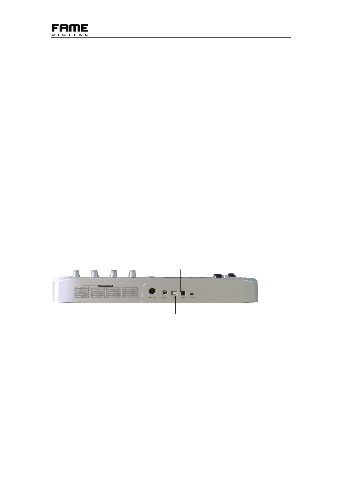
3.1.2. REAR PANEL
........................................................................................................
7
3.2. CONNECTION/POWER/CONTROL
................................................................................
8
3.3. ASSIGN CONTROLLERS
.................................................................................................
8
3.4. PEDAL RESISTANCE CURVE
.........................................................................................
8
3.5. TEMPO
................................................................................................................................
9
3.6. PROGRAM
..........................................................................................................................
9
3.7. MIDI CHANNEL
.................................................................................................................
9
3.8. TRANSPOSE
.....................................................................................................................
10
3.9. OCTAVE
............................................................................................................................
10
3.10. DUAL
...............................................................................................................................
10
3.11. SPLIT
...............................................................................................................................
10
3.12. SPLIT POINT
..................................................................................................................
11
3.13. MTC
.................................................................................................................................
11
3.14. ACTIVE SENSING
.........................................................................................................
11
3.15. LOCK
...............................................................................................................................
11
3.16. MUTE
...............................................................................................................................
11
3.17. SNAP SHOT
....................................................................................................................
11
3.18. UPLOAD/DOWNLOAD
.................................................................................................
12
3.19. PEDAL POLARITY
........................................................................................................
13
3.20. SWITCH DIAL FUNCTION GROUPS
.........................................................................
13
3.21. ALL NOTE OFF
..............................................................................................................
13
3.22. ALL SOUND OFF
...........................................................................................................
14
3.23. RESET ALL CONTROLLERS
.......................................................................................
14
3.24. GM/GS/XG ON
...............................................................................................................
14
3.25. GM ON
.............................................................................................................................
14
3.26. GM2 ON
...........................................................................................................................
14
3.27. GS ON
..............................................................................................................................
14
3.28. XG ON
.............................................................................................................................
15
3.29. PRESET
...........................................................................................................................
15
3.30. CLEAN
.............................................................................................................................
15
3.31. RESET
..............................................................................................................................
15
4. APPENDIX
..................................................................................................................................
16
4.1. APPENDIX 1 ASSIGNABLE CONTROLLER LIST
.......................................................
16
4.2. APPENDIX 2 ASSIGNABLE CONTROLLER PARAMETER LIST
..............................
16
4.3. APPENDIX 3 LED
STATUS
LIST
....................................................................................
19
4.4. APPENDIX 4 TECHNICAL SPECIFICATIONS
.............................................................
20