Phonic DFX256 User manual


This triangle on your component alerts you
toimportantoperatingandmaintenancein-
structions in this accompanying literature.
SAFETYPRECAUTIONS!
WARNING - TO REDUCE THE RISK OF FIRE OR ELECTRIC SHOCK, DO NOT
EXPOSE THIS UNIT TO RAIN OR MOISTURE.
Do not allow water or liquids to be spilled into this unit. If the unit has been exposed to rain or liquids, please
unplug the power cord immediately from the outlet (with DRY HANDS) and get a qualified service technician
to check it. Keep this unit away from heat sources such as radiators, heat registers, stoves, etc.
This unit contains no user-serviceable parts. Refer all service needs to a
qualified service engineer through a Phonic dealer.
CAUTION:
TO REDUCE THE RISK OF ELECTRIC SHOCK, DO NOT REMOVE COVERS (OR
BACK). NO USER-SERVICEABLE PARTS ARE INSIDE. REFERALL SERVICING TO
A QUALIFIED SERVICE PERSONNEL.
Keep this unit clean by using a soft dry brush and occasionally wiping it with a damp cloth. Do not use
any other solvents, which may damage the paint or plastic parts. Regular care and inspection will be
rewarded by a long product life and maximum reliability.
This unit was carefully packed at the manufacturing site and the packing box was designed to protect the
unit from rough handling. We recommend that you carefully examine the packaging and its contents for any
signs of physical damage which may have occurred during transportation.
If the unit is damaged: Notify your dealer and the shipping company immediately.
Claims for damage or replacement may not be granted if not reported properly or in a timely manner.
This triangle on your component alerts you
to the presence of uninsulated “ danger-
ous voltage” inside the enclosure that may
be sufficient to constitute a risk of shock.
SAFTY PRECAUTIONS
PHONIC CORPORATIONPage 2 DFX256 USER’S MANUAL

INTRODUCTION...................................................4
FEATURES...........................................................4
GETTING STARTED.............................................4
FRONT-PANEL DESCRIPTION.............................5
INPUTLEVELCONTROL
PEAK(L/R) INDICATORS
MIX(DRY/WET)CONTROL
LEDDISPLAY
EFFECTMODES CHART
EFFECT MODE, KEYS
PATTERNSELECTOR
OUTPUTCONTROL
POWERSWITCH
REAR-PANEL DESCRIPTION...............................5
AC 10V IN INLET
FOOTSWITCH
OUTPUT(LEFT&RIGHT)
INPUT(LEFT/MONO&RIGHT)
PRESET PROGRAMS.........................................6
EFFECT 1: ROOM...........................................6
EFFECT 2: HALL..............................................6
EFFECT 3: PLATE............................................7
PHONIC CORPORATION Page 3
DFX256 USER’S MANUAL
EFFECT 4: CHAMBER....................................7
EFFECT 5: GATED REVERB...........................8
EFFECT 6: REVERSE REVERB......................8
EFFECT 7: MONO DELAY..............................9
EFFECT 8: OFFSET DELAY...........................9
EFFECT 9: MONO TAPPEDDELAY...............10
EFFECT 10: MULTI-TAP &DUALDELAY.........10
EFFECT 11: ST CHORUS...............................11
EFFECT 12: ST FLANGE................................11
EFFECT 13: CHORUS+DELAY.....................12
EFFECT 14: FLANGE + REVERB..................12
EFFECT 15: CHORUS + REVERB..................13
EFFECT 16: DELAY + REVERB....................13
CONTENTS
SAMPLE CONNECTIONS................................14
One mono cord in, one mono cord out
One mono cord in, two mono cords out
Two mono cords in and out
SPECIFICATIONS.............................................15

INTRINTR
INTRINTR
INTRODUCTIONODUCTION
ODUCTIONODUCTION
ODUCTION
CongratulationsonyourpurchaseofthePhonicDFX256
digital reverberator. The DFX256 is a high quality and
easy-to-use stereo digital reverberator. To take full ad-
vantage of the DFX256’s functions, and enjoy a long
and trouble-free use, please read this user’s manual
carefully and keep it for future reference.
FEATURES
255 effect programs available
Programs include reverb, delay, echo, flanger,
chorus, panner effects and combinations
24 bit digital signal processing plus 20 bit AD/DA
conversions
True stereo reverb
Easy-to-read 2-digit LED display
Compact “1U” rack mount dimensions
Foot SW Jacks allow the user of a footswitch to
mute the effect
Auto-bypass when power is off.
Bi-color Peak LEDs enable easy setup of the opti-
mum input level
A professional quality digital reverb designed for
musical instruments,recording, and sound reinforce-
ment
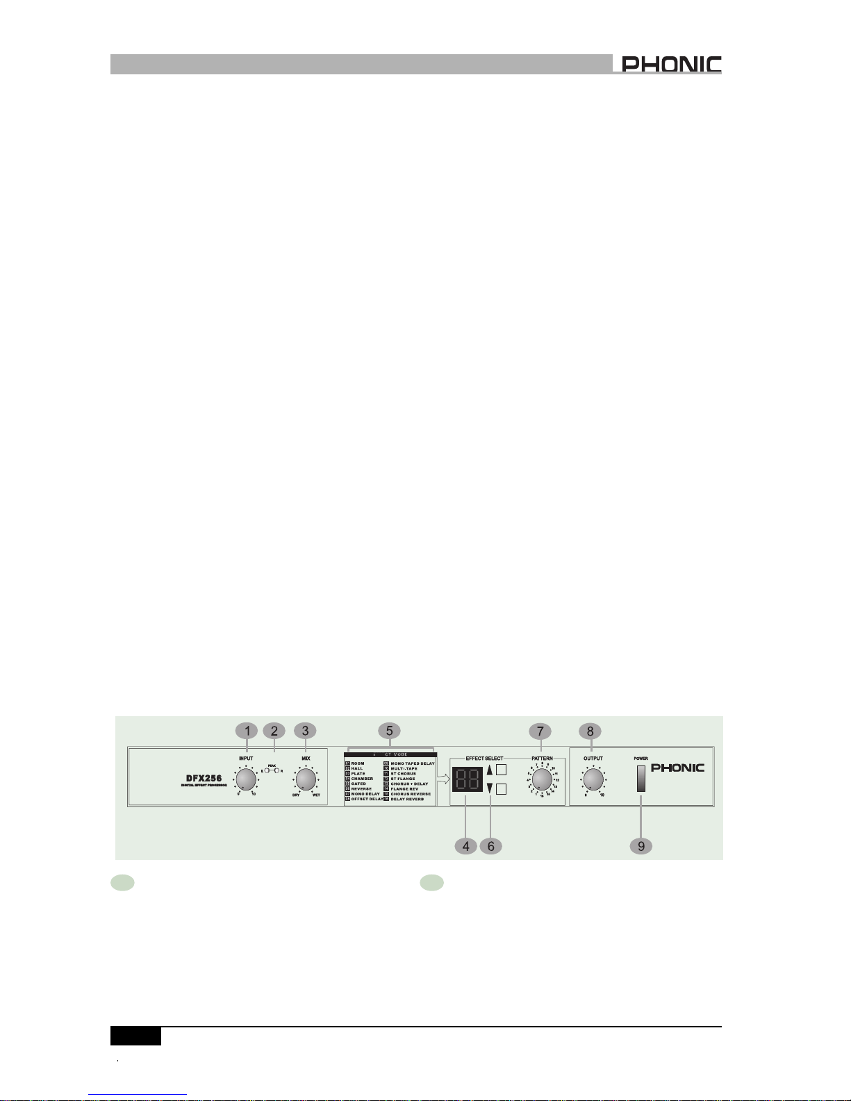
1 INPUT LEVEL CONTROL
The input level control sets the level going into the
DFX256. You should set the level so that Peak (2)
indicators only flash RED occasionally.
PHONIC CORPORATIONPage 4
INTRODUCTION / FEATURES / GETTINGSTARTED / FRONT-PANELDESCRIPTION
DFX256 USER’S MANUAL
FRFR
FRFR
FRONTONT
ONTONT
ONT-P-P
-P-P
-PANEL DESCRIPTIONANEL DESCRIPTION
ANEL DESCRIPTIONANEL DESCRIPTION
ANEL DESCRIPTION
1. Check the AC voltage before connecting
the plug. Choose the main supply for the
sound system with care. Do not share
sockets or earthing with light dimmers.
2. Run audio cables separately from dimmer
wiring, using balanced lines wherever
possible. If necessary, cross audio and
lighting cables at 90oright angles to mini-
mize the possibility of interference. Keep
unbalanced cabling as short as possible.
3. Check your cables regularly and label each
end for easy identification.
4. Before switching on the main power, keep
all output rotary faders all the way down to
prevent damage or excessive noise
caused by bad level adjustment, wrong
wiring, defective cables,or bad
connections.
5. Always turn on the DFX256 before the
power amplifier; turn off the DFX256 after
turning off the amplifier.
6. Always turn off the unit before connecting
or disconnecting the unit to the power
source.
7. Never use any solvents to clean the unit.
Clean it with a soft, dry cloth.
GETTING STGETTING ST
GETTING STARAR
ARAR
ARTEDTED
TEDTED
TED
2 PEAK (L/R) INDICATORS
They are bi-color LEDs. In most cases, they light up
green as “signal” LEDs, and will turn red when the
DFX256 is receiving a peak level signal. In general, a
few red flashes every now and then will not be a
problem. If the LEDs flash red very often or remain on
red, then reduce the input level control (1).

3 MIX (DRY / WET) CONTROL
This control sets the balance between the unaf-
fected signal coming through the inputs and the
effects being generated by the DFX256 i.e. the
balance of wet (effect) and dry (no effect)
sounds. By keeping the Mix somewhere in the
center, a blend of dry and wet signal can be
achieved.
4 LED DISPLAY
This 7-segment display indicates the current ef-
fect program in Program mode.
5 EFFECT MODES CHART
This chart shows you what 16 effect modes are
in the DFX256.
PHONIC CORPORATION Page 5
DFX256 USER’S MANUAL
REAR-PANELDESCRIPTION
10 AC 10V IN INLET
The supplied AC Adapter is plugged into this
connector.
11 FOOTSWITCH
This is a 1/4” stereo phone jack. If a foot switch
is connected to this jack, you can use your foot
to switch the effect program on/off (bypass).
REAR-PANEL DESCRIPTION
12 OUTPUT (LEFT & RIGHT)
There are 1/4” phone jacks which connect to
devices such as the effects returns on a mixing
console or power amplifier inputs. For mono
applications, use the “Left” output.
13 INPUT (LEFT/MONO & RIGHT)
There are 1/4” phone jacks which connect to
sources such as the effects sends of mixing
consoles. For mono applications, use the “Left/
Mono” input.
6 EFFECT MODE ¡µ¡µ
¡µ¡µ
¡µ
,,
,,
,
¡¾¡¾
¡¾¡¾
¡¾KEYS
These keys allow you to select the various effect mode.
7 PATTERN SELECTOR
This rotary Selector allows you to set one of 16 pa
tterns of the current effects.
8 OUTPUT CONTROL
This rotary control sets the level going to the amplifier or
mixer from the output of the DFX256.
9 POWER SWITCH
This switch turns the powerof the DFX256 on/off.When
power is off, the DFX256 will be in signal bypass
position automatically i.e. this feature allows the
direct signal to pass through the DFX256 even
when the power is not switched on.

PRESETPROGRAMS
EEFFECT 1: ROOM
EEFFECT 2: HALL
PHONIC CORPORATIONPage 6 DFX 256 USER’S MANUAL
PRESET PROGRAMSPRESET PROGRAMS
PRESET PROGRAMS

PHONIC CORPORATION Page 7
DFX 256 USER’S MANUAL
PRESET PROGRAMS
EFFECT 3: PLATE
EFFECT 4: CHAMBER

PRESET PROGRAMS
PHONIC CORPORATIONPage 8 DFX 256 USER’S MANUAL
EFFECT 5: GATED REVERB
EFFECT 6: REVERSE REVERB

PRESET PROGRAMS
PHONICCORPORATION Page 9DFX 256 USER’SMANUAL
EFFECT 7: MONO DELAY
EFFECT 8: OFFSET DELAY

PRESET PROGRAMS
PHONIC CORPORATION
Page 10 DFX 256 USER’S MANUAL
EFFECT 9: MONO TAPPED DELAY
EFFECT 10: MULTI-TAPE & DUAL DELAY

PRESET PROGRAMS
PHONIC CORPORATION Page 11
DFX 256 USER’S MANUAL
EFFECT 11: ST CHORUS
EFFECT 12: ST FLANGE

PRESET PROGRAMS
PHONIC CORPORATION
Page 12 DFX 256 USER’S MANUAL
EFFECT 13: CHORUS + DELAY
EFFECT 14: FLANGE + REVERB

PRESET PROGRAMS
PHONIC CORPORATION Page 13
DFX 256 USER’S MANUAL
EFFECT 16: DELAY + REVERB
EFFECT 15: CHORUS + REVERB

SAMPLE CONNECTIONSSAMPLE CONNECTIONS
SAMPLE CONNECTIONS
ONE MONO CORD IN, ONE MONO CORD OUT (to an amplification system or mixer input)
ONE MONO CORD IN, TWO MONO CORDS OUT (to a stereo amplifier or two mixer inputs)
TWO MONO CORDS IN AND OUT (to a stereo amplifier or two mixer inputs)
This can be stereo signal in/out or mono signal in/out.
PHONIC CORPORATION
Page 14 DFX 256 USER’S MANUAL
SAMPLECONNECTIONS
INSTRUMENT OF
EFFECTS SEND
TO MIXING CONSOLE OR AMPLIFIER
INSTRUMENT OF
EFFECTS SEND
TO MIXING CONSOLE OR AMPLIFIER
INSTRUMENT OF
EFFECTS SEND
TO MIXING CONSOLE OR AMPLIFIER

PHONIC CORPORATION Page 15
DFX 256 USER’S MANUAL
SPECIFICATIONS
SEPCIFICASEPCIFICA
SEPCIFICASEPCIFICA
SEPCIFICATIONSTIONS
TIONSTIONS
TIONS
The specifications are subject to change without notice.

PHONIC CORPORATION
Page 16 DFX 256 USER’S MANUAL
Other manuals for DFX256
2
Table of contents
Other Phonic Recording Equipment manuals

Phonic
Phonic A6600B User manual

Phonic
Phonic i2600 User manual

Phonic
Phonic MQ3300 User manual

Phonic
Phonic i7300 ReverbMaster User manual

Phonic
Phonic MQ 3229 User manual

Phonic
Phonic MM1705a User manual

Phonic
Phonic MQ3300 User manual

Phonic
Phonic DFX256 User manual

Phonic
Phonic i7300 ReverbMaster User manual

Phonic
Phonic MICRO VI User manual