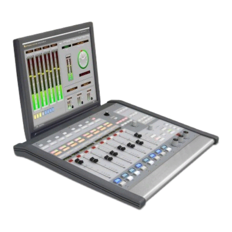
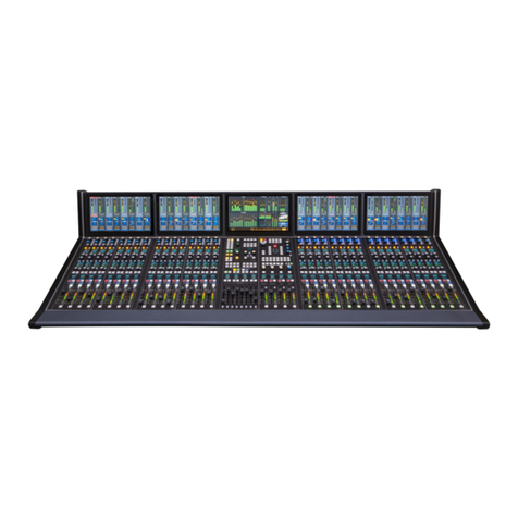
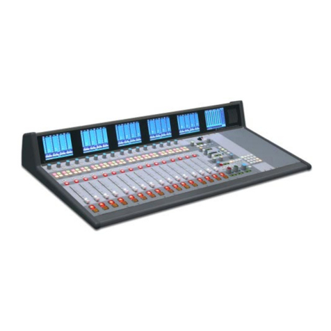
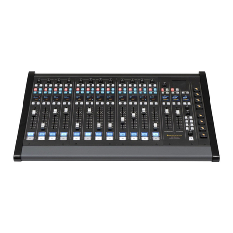
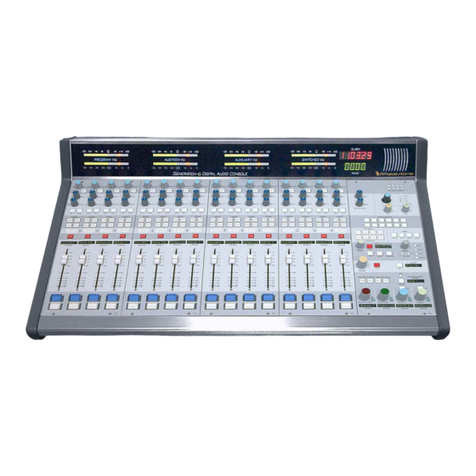
Wheatstone A-6000 User manual

A-6000 Audio Console
TECHNICAL MANUAL
May 1998
600 Industrial Drive, New Bern, NC. 28562
(tel 252-638-7000 / fax 252-637-1285)

WHEATSTONE CORPORATION
600 Industrial Drive
New Bern, NC. 28562
(tel 252-638-7000/fax 252-637-1285)
A-6000 Radio On-Air Console Technical Manual - 2nd Edition (revised)A-6000 Radio On-Air Console Technical Manual - 2nd Edition (revised)
A-6000 Radio On-Air Console Technical Manual - 2nd Edition (revised)
©1998 Wheatstone Corporation
A-6000 / May 98

Addenda
A-6000 / Nov 00
IMPORTANT:
Please note the following updates
to this technical manual:
GLOBAL CHANGE – ALL MODULE SCHEMATICS & LOAD SHEETS
Delete type 7818 & 7918 regulators.
METERBRIDGE:
A DB-9 connector has been added, on the back side of the meterbridge, for the
optional studio turret unit. It is the connector closest to the inside.
MONO AND STEREO INPUT MODULES:
The IFB Ouputs listed on I/O connector pinout pages 3-4, 3-5, 3-9 and 3-10 refer to the
Bus Minus option outputs discussed in "Overview Chapter" (pages 1-2 and 1-5).
OUTPUT MASTER MODULE LOAD SHEET:
Resistors R68 & R74 are now 11kΩ1%.
METER OUTPUT MODULE SCHEMATIC AND LOAD SHEET:
The optocoupler, U8 has been changed to a 4N32.
TM-6 TIMER CONTROL PCB LOAD SHEET:
Page 6-16 has been deleted. The timer control has been incorporated into the
MO-6000 module. (see schematic page 5-17).
SPN-6000 SUPERPHONE INPUT MODULE SCHEMATIC & LOAD SHEET:
U1 has been changed to an SL1X-6000 PCB assembly.
U2 has been changed to an SPH2X-6000 PCB assembly.
Schematic and PCB load sheet for this assembly is included immediately
following this page.
ICM-6000 INTERCOM MODULE:
Resistors R36 thru R39 & R58 thru R61 are now .4A polyswitch fuses.
CONTROL ROOM MODULE SCHEMATIC AND LOAD SHEET:
Resistors R204-R207 (24Ω) have been changed to polyswitches F2 and F3 (.17A).
!
Addenda - Page 1

CT1
20
19
18
17
16
1
15
14
13
12
11
10
9
8
7
6
5
4
3
2
GND
GND
GND
GND
GND
VCC
GND
GND
VCC
GND
13 12
U3
74AC14
11 10
U3
74AC14
98
U3
74AC14
12
U3
74AC14
43
U3
74AC14
56
U3
74AC14
GND
VCC
19
18
17
16
15
14
13
12
9
8
7
6
5
4
3
2
1
11
16V8
U4
I9/OE F0
F1
F2
F3
F4
F5
F6
F7
I8
I7
I6
I5
I4
I3
I2
I1
I0/CLK
U1
1
2
3
4
5
6
8
11
12
74HC30
VCC
GND
GND
GND
GND
GND
GND GND
21
U2
74AC14
1213
U2
74AC14
1011
U2
74AC14
89
U2
74AC14
34
U2
74AC14
65
U2
74AC14
GND
GND GND
GND
VCC
VIEWED FROM ABOVE
(COMPONENT SIDE)
74HC14
IC PINOUT
VCC
Od
Ob
Oa
14
13
12
11
10
9
87
6
5
4
3
2
1
VSS
O2c
Oe
Ie
Ic
Ia
Ib
Id
Of
If
VIEWED FROM ABOVE
(COMPONENT SIDE)
74HC30
IC PINOUT
VCC 14
13
12
11
10
9
87
6
5
4
3
2
1
VSS
I1
I2
I3
I4
I5
I6
N/C
N/C
N/C
I7
I8
OUT
220
R9
220
R10
220
R11
220
R12
220
R13
R1
4.99K
1.00K
R2
1.00K
R3
1.00K
R4
1.00K
R5
1.00K
R6
R7
4.99K
220
R14
220
R15
1.00K
R8
0.1uF
C10
0.1uF
C8
600 Industrial Drive
New Bern, NC 28562
Page 1-1
1 OF 1
SA
_
SL1X-6000
SL1X-6000 PCB
13S0039
W# 700230
Stereo Line Input Module Fix Card
Schematic - Sheet 1 of 1
A-6000/Dec 2000
12-6-00
REVSIZE
SCALE
FSCM NO. DWG. NO.
SHEET
CONTRACT NO.
APPROVALS DATE
DRAWN
CHECKED
ISSUED C
1234
4321
A
C
DD
C
B
A
B
C1
.22uF
C2
.22uF
C3
.22uF
C4
.22uF
C5
.22uF
C6
.22uF
C7
.22uF
1uF
C9
ON/MXD
STEREO/REC
LEFT
RIGHT/MXA
MONO/MXB
PRE/MXC
A/1
A/1SW
B/2SW
MODE/RECSW
PRE/MXASW
ON/MXBSW
MXDSW
B/2
MXCSW


GND
GND
GND
GND
GND
GND
GND
GND
1213
U4
74AC14
1011
U4
74AC14
89
U4
74AC14
21
U4
74AC14
34
U4
74AC14
65
U4
74AC14
GND
74HC30
12
11
8
6
5
4
3
2
1
U3
GND
GND
GND
GND
GND
GND GND
12
U1
74AC14
13 12
U1
74AC14
11 10
U1
74AC14
98
U1
74AC14
43
U1
74AC14
56
U1
74AC14
GND
GND GND
GND
22
21
20
19
18
17
16
15
14
1
2
3
4
5
6
7
8
9
10
11
13
23
U2
F0
F1
F2
F3
F4
F5
F6
F7
I11/OE
I13
I12
I10
I9
I8
I7
I6
I5
I4
I3
I2
I1
I0/CLK
P20V8
GND GND
GND GND
GND
74HC14
IC PINOUT
VIEWED FROM ABOVE
(COMPONENT SIDE)
VCC
Od
Ob
Oa
14
13
12
11
10
9
87
6
5
4
3
2
1
VSS
O2c
Oe
Ie
Ic
Ia
Ib
Id
Of
If
74HC30
IC PINOUT
VIEWED FROM ABOVE
(COMPONENT SIDE)
VCC 14
13
12
11
10
9
87
6
5
4
3
2
1
VSS
I1
I2
I3
I4
I5
I6
N/C
N/C
N/C
I7
I8
OUT
0.1uF
C1
0.1uF
C12
0.1uF
C13
220
R12
220
R13
220
R14
220
R15
220
R16
220
R17
220
R18
220
R19
220
R11
4.99K
R10
R2
1.00K
R3
1.00K
R4
1.00K
R5
1.00K
R6
1.00K
R7
1.00K
R8
1.00K
1.00K
R9
1.00K
R1
CT1
24
21
22
23
20
19
18
17
16
1
15
14
13
12
11
10
9
8
7
6
5
4
3
2
4148
D1
4148
D2
600 Industrial Drive
New Bern, NC 28562
SPN-6000 Super Phone Module Fix Card
Schematic - Sheet 1 of 1
_
SA
1 OF 1
Page 1-1
W# 700233 SPH2X-6000 PCB
13S0041
SPH2X-6000
A-6000/Dec 2000
12-6-00
REVSIZE
SCALE
FSCM NO. DWG. NO.
SHEET
CONTRACT NO.
APPROVALS DATE
DRAWN
CHECKED
ISSUED C
1234
4321
A
C
DD
C
B
A
B
1uF
C11
C3
.22uF
C4
.22uF
C5
.22uF
C6
.22uF
C7
.22uF
C8
.22uF
C9
.22uF
C10
.22uF
C2
.22uF
VCC
VCC VCC VCC VCC
VCC
CUE
OFF
AUX
UTL
ARM
SOLO
AUD
AUDSW
AUXSW
UTLSW
ARMSW
SOLOSW
ONSW
PGM
CUESW
OFFSW
SOLODROP
CUEDROP
PGMSW


Module Removal Tools
Your Wheatstone audio console is equipped with two "module
extractor tools" which are mounted in the front panel of the
console mainframe.
All modules are held into the console mainframe by two mounting
screws (top and bottom) which, whenremoved,leavespecially threaded
holes that accept the two extractor tools.
To remove a module faceplate from the mainframe:
Remove the top and bottom module mounting screws, unscrew the
extractor tools from the mainframe, and screw each tool into a module
mountinghole.Use onlyfour orfive turns (donot over-insert!).Using the
extractor tools as handles, pull the module straight up out of the
mainframe.

Contents - 1
A-6000 / May 94
TABLE OF CONTENTS
Table of Contents
OVERVIEW AND APPLICATIONS
Overview.......................................................................................................1-2
Functions................................................................................................................ 1-2
Features .................................................................................................................. 1-2
Internal Technology ............................................................................................... 1-2
Stereo Input Modules (SL-6000)
Digital Source Control ........................................................................................... 1-3
A/B Source Control ............................................................................................... 1-3
Auxiliary Send ....................................................................................................... 1-3
Channel Monitor .................................................................................................... 1-3
Electronic Bus Assign............................................................................................ 1-3
Send Options.......................................................................................................... 1-4
Electronic Mode Selector....................................................................................... 1-4
Balance Control ..................................................................................................... 1-4
Machine Sequence ................................................................................................. 1-4
Command Logic (automatic muting, tallys & machine control) ........................... 1-4
Microphone Modules (ML-6000)
Low-Noise Mic Preamp......................................................................................... 1-5
IFB Bus-Minus® ................................................................................................... 1-5
The Fader ............................................................................................................... 1-5
The Hidden Console (internal signal routing) ....................................................... 1-5
Equalization ........................................................................................................... 1-6
Audio Taper Controls ............................................................................................ 1-6
Hidden Value (internal electronics) ....................................................................... 1-6
Outputs and Metering (OM-6000/MO-6000)
Master Output Modules ......................................................................................... 1-7
Gain Trim............................................................................................................... 1-7
Mono Sum.............................................................................................................. 1-7
I/O Ports ................................................................................................................. 1-7
The Event Timer .................................................................................................... 1-7
Total Metering ....................................................................................................... 1-7
Monitor Modules (CR-6000/SC-6000)
General ................................................................................................................... 1-8
Stereo Cue System ................................................................................................. 1-8
Headphone Monitor ............................................................................................... 1-8
Studio Monitor ....................................................................................................... 1-8
Control Room Monitor .......................................................................................... 1-8
Tallys ..................................................................................................................... 1-8
AccessoryModules/Mainframe/Meterbridge
Telephones ............................................................................................................. 1-9
Superphone (SPN-6000) ........................................................................................ 1-9
Intercom (ICM-6000) ............................................................................................ 1-9
Stereo Line Preselector (LS-6000)....................................................................... 1-10
Tape Remote (TR-6000) ...................................................................................... 1-10
The Console Mainframe ...................................................................................... 1-10
The Console Meterbridge .................................................................................... 1-10
The I/O Connector System .................................................................................. 1-10
Contents - 2
A-6000 / May 94
TABLE OF CONTENTS
MAINFRAME INSTALLATION
UNPACKING THE CONSOLE.................................................................................... 2-1
MAINFRAME INSTALLATION ................................................................................. 2-1
SYSTEM GROUND...................................................................................................... 2-2
Typical Grounding Scheme (dwg) ............................................................................. 2-3
Further Grounding Details ......................................................................................... 2-3
THE CONSOLE POWER SUPPLY ............................................................................. 2-4
Power Supply Functions............................................................................................. 2-4
Dual Redundant Fail-safe Supply .............................................................................. 2-5
ENERGIZING THE CONSOLE ................................................................................... 2-5
CONSOLE I/O CONNECTIONS
General ................................................................................................................
3-2
The Insulation Displacement Connector System .......................................................3-2
Connection Procedures...............................................................................................3-3
Balanced vs Unbalanced I/O Connections .................................................................3-3
Mono Mic/Line Input Module (ML-6000)
I/O Pinout Diagram ....................................................................................................3-4
Audio Connections .....................................................................................................3-5
Control Ports ..............................................................................................................3-5
Dipswitch Controlled Functions.................................................................................3-7
Stereo Line Input Module (SL-6000)
I/O Pinout Diagram ....................................................................................................3-9
Audio Connections .....................................................................................................3-10
Control Ports ..............................................................................................................3-11
Dipswitch Controlled Functions.................................................................................3-11
Output Master Module (OM-6000)
I/O Pinout Diagram (Output #1) ................................................................................3-14
Audio Connections (Output #1) .................................................................................3-15
Dipswitch Controlled Functions (Output #1).............................................................3-16
I/O Pinout Diagram (Output #2) ................................................................................3-17
Audio Connections (Output #2) .................................................................................3-18
Dipswitch Controlled Functions (Output #2).............................................................3-19
Control Room Monitor Module (CR-6000)
I/O Pinout Diagram ....................................................................................................3-20
Audio & Control Connections....................................................................................3-21
Dipswitch Controlled Functions.................................................................................3-22
Studio Monitor Module (optional) (SC-6000)
I/O Pinout Diagram ....................................................................................................3-23
Audio & Control Connections....................................................................................3-24
Dipswitch Controlled Functions.................................................................................3-25
Meter Output Module (MO-6000)
I/O Pinout Diagram ....................................................................................................3-26
Audio Connections .....................................................................................................3-27
Intercom Module (optional) (ICM-6000)
I/O Pinout Diagram ....................................................................................................3-28
Audio & Control Connections....................................................................................3-29
Stereo Line Selector Module (optional) (LS-6000)
I/O Pinout Diagram ....................................................................................................3-30
Audio Connections .....................................................................................................3-31
A-6000 / Aug 99

Contents - 3
A-6000 / May 94
TABLE OF CONTENTS
A-6000 / Jul 02
Superphone Module (optional) (SPN-6000)
I/O Pinout Diagram ....................................................................................................3-32
Audio Connections .....................................................................................................3-33
Control Connections...................................................................................................3-34
Dipswitch Controlled Functions.................................................................................3-34
Tape Remote Module (optional) (TR-6000)
I/O Pinout Diagram ....................................................................................................3-36
Audio Connections .....................................................................................................3-37
CONSOLE MODULES
Mono Mic/Line Input ...................................................................................................4-2
Stereo Line Input..........................................................................................................4-6
Output Masters .............................................................................................................4-10
Meter Output ................................................................................................................4-11
Timer Control...............................................................................................................4-12
Clock Control ...............................................................................................................4-12a
Control Room Monitor.................................................................................................4-13
Studio Control (optional) .............................................................................................4-15
Intercom (optional) ......................................................................................................4-16
Stereo Line Selector (optional) ....................................................................................4-17
Superphone (optional) ..................................................................................................4-18
Tape Remote (optional) ...............................................................................................4-20
SCHEMATIC DRAWINGS
A-6000 Performance Specifications ............................................................................5-2
Console Bus Chart .......................................................................................................5-3
Mono Mic/Line Input
bus chart .......................................................................................................................5-4
schematic (5 pages) ......................................................................................................5-5
schematic (IPS-6000A) ................................................................................................5-6
schematic (w/optional EQ)...........................................................................................5-6a
Stereo Line Input
bus chart .......................................................................................................................5-7
schematic (5 pages) ......................................................................................................5-8
schematic (IPS-6000A) ................................................................................................5-9
schematic (w/optional EQ)...........................................................................................5-10
Output Master
bus chart .......................................................................................................................5-12
schematic (2 pages) ......................................................................................................5-13
Meter Output
bus chart .......................................................................................................................5-15
schematic (2 pages) ......................................................................................................5-16
Timer schematic ..................................................................................................5-18
Control Room
bus chart .......................................................................................................................5-19
schematic (5 pages) ......................................................................................................5-20
Switch Card schematic (CR, SC & SPN-6000 modules) ...................................5-21
Source Select schematic (CR & SC-6000 modules) ...........................................5-22

Contents - 4
A-6000 / May 94
TABLE OF CONTENTS
Studio Control
bus chart .......................................................................................................................5-23
schematic (2 pages) ......................................................................................................5-24
Intercom
bus chart .......................................................................................................................5-26
schematic......................................................................................................................5-27
Line Selector schematic (2 pages) ......................................................................5-28
Superphone
bus chart .......................................................................................................................5-30
schematic (2 pages) ......................................................................................................5-31
Tape Remote schematic ......................................................................................5-33
Clock schematic ...................................................................................................5-34
Power Supply schematic .....................................................................................5-35
Power Supply Relay Card schematic ................................................................5-36
LOAD SHEETS
Mono Mic/Line Input ...................................................................................................6-2
Mono Mic/Line Input (w/EQ)......................................................................................6-2a
Stereo Line Input..........................................................................................................6-3
Stereo Line Input (w/EQ).............................................................................................6-4
Output Master ..............................................................................................................6-5
Meter Output ................................................................................................................6-6
Control Room Monitor.................................................................................................6-7
Studio Control ..............................................................................................................6-8
Source Select PCB (CR & SC monitor modules) ........................................................6-9
Intercom .......................................................................................................................6-10
Line Selector ................................................................................................................6-11
Superphone...................................................................................................................6-12
Tape Remote ................................................................................................................6-13
Main Interface Board ...................................................................................................6-14
Timer ............................................................................................................................6-15
Clock ............................................................................................................................6-17
Clock Control ...............................................................................................................6-18
Power Supply ...............................................................................................................6-19
Power Supply Relay Card ............................................................................................6-20
APPENDIX
BALANCED vs UNBALANCED I/O CONNECTIONS ...........................................A-1
Typical Unbalanced Connections (dwg) ................................................................A-2
NOTES ON LEVEL MEASUREMENT .....................................................................A-3
TROUBLESHOOTING...............................................................................................A-3
Basic Procedures.....................................................................................................A-3
Testing a “Live” Console – Precautions .................................................................A-3
Integrated Circuits ..................................................................................................A-4
OTHER DETAILS.......................................................................................................A-5
EXTERNAL SOURCE MACHINE INTERFACES ...................................................A-6
A-6000 / Jul 02

Contents - 5
A-6000 / May 94
TABLE OF CONTENTS
A-6000 / Apr 99
GENERAL ...................................................................................................................A-6
Start/Stop Control from Channel ON/OFF Switches .............................................A-6
Tallyback "READY" Functions .............................................................................A-7
Remote Control of Channel ON/OFF.....................................................................A-8
INDIVIDUAL SOURCE MACHINES .......................................................................A-9
DENON 951A CD Player.......................................................................................A-9
DENON 995R MD Player ......................................................................................A-11
Fidelipac DCR 1000 Floppy Cart Player................................................................A-13
Sony MDS-B3 Player .............................................................................................A-15
ADDITIONAL INFORMATION................................................................................A-16
SL-6000 OFF Circuit Modification .............................................................................A-16
Double Connection to One Pin Wiring Procedure.......................................................A-17

Page 1 - 1
A-6000 / Nov 93
CONSOLE I/O CONNECTIONS
Overview and Applications
CHAPTER CONTENTS
Overview.......................................................................................................1-2
Functions ................................................................................... 1-2
Features ..................................................................................... 1-2
Internal Technology .................................................................... 1-2
Stereo Input Modules (SL-6000)
Digital Source Control ................................................................ 1-3
A/B Source Control .................................................................... 1-3
Auxiliary Send ............................................................................ 1-3
Channel Monitor......................................................................... 1-3
Electronic Bus Assign ................................................................. 1-3
Send Options .............................................................................. 1-4
Electronic Mode Selector ............................................................. 1-4
Balance Control .......................................................................... 1-4
Machine Sequence ...................................................................... 1-4
Command Logic (automatic muting, tallys & machine control) .... 1-4
Microphone Modules (ML-6000)
Low-Noise Mic Preamp ................................................................ 1-5
IFB Bus-Minus® ......................................................................... 1-5
The Fader ................................................................................... 1-5
The Hidden Console (internal signal routing)............................... 1-5
Equalization ............................................................................... 1-6
Audio Taper Controls .................................................................. 1-6
Hidden Value (internal electronics) ............................................. 1-6
Outputs and Metering (OM-6000/MO-6000)
Master Output Modules .............................................................. 1-7
Gain Trim ................................................................................... 1-7
Mono Sum .................................................................................. 1-7
I/O Ports .................................................................................... 1-7
The Event Timer ......................................................................... 1-7
Total Metering ............................................................................ 1-7
Monitor Modules (CR-6000/SC-6000)
General ...................................................................................... 1-8
Stereo Cue System...................................................................... 1-8
Headphone Monitor .................................................................... 1-8
Studio Monitor ........................................................................... 1-8
Control Room Monitor ................................................................ 1-8
Tallys ......................................................................................... 1-8
AccessoryModules/Mainframe/Meterbridge
Telephones ................................................................................. 1-9
Superphone (SPN-6000).............................................................. 1-9
Intercom (ICM-6000) ................................................................... 1-9
Stereo Line Preselector (LS-6000) ...............................................1-10
Tape Remote (TR-6000)..............................................................1-10
The Console Mainframe .............................................................1-10
The Console Meterbridge ...........................................................1-10
The I/O Connector System ........................................................1-10

A-6000 / Nov 93 Page 1 - 2
O
VERVIEW
The A-6000 has been engineered spe-
cifically for major market stations that
demand a lot of function and need to lead
with technical excellence. This series
begins with an open architecture main-
frame that allows clients to place any of
the modules anywhere in any combina-
tion within the console frame, giving lay-
out top priority, and allowing easy recon-
figuration as format needs change. Main-
frames are available in sizes dictated by
your specific needs, with either six or
eight VU meters and a choice of mono or
stereo cue speakers.
Input modules are offered as a rather
large array of feature combinations, and
while this brochure depicts only twelve
inputs, it is possible to order these mod-
ules with feature combinations or dele-
tions exactly as your requirements de-
mand.
F
UNCTIONS
The A-6000 is loaded with capability.
The input modules can be equipped with
a station router input function that allows
each channel to select its source through
individual UP, DOWN and TAKE buttons
and display or preview this source on an
alpha-numeric display above each fader.
Wheatstone’s exclusive Bus-Minus®
system allows every input channel to pro-
duce its own mix-minus—a powerful
feature for news, sports and complex
telephone formats. The modules can
have two, three or four stereo program
assign buttons. You can have a stereo
send or a pair of mono send knobs, a
mode selector, or even Wheatstone’s
auto sequence function, which allows
you to trigger a bank of carts or CD
players with a stroke of a single start
button.
The monitor modules let you select
the four stereo program busses and
four external inputs, as well as each of
the four mix-minus buses and two
auxiliary send buses so that program
set-up is fast. We even provide a
headphone polarity switch so the an-
nouncer can phase his headphones for
maximum clarity relative to his own in-
ternal auditory path.
Wheatstone’s exclusive superphone
module allows complete phone seg-
ment operation directly from one mod-
ule. No need to tie up or operate other
line modules for your hybrids. You can
select any one of the four mix-minus
buses to feed the callers; you can cue
the callers without monitor interruption;
feed a multitrack recorder separate
caller, announcer and program tracks.
You can have on-air or off-air operation,
and individually adjust caller level. This
module greatly simplifies phone
segments and reduces operator
confusion and error in program control.
The technology inside is different. We
utilize all differentially-balanced active com-
bining networks to achieve super crosstalk
and separation performance, and to reject
electrostatic and magnetic interference from
the buses. Absolutely all switching (not just
critical paths) is accomplished electronically
in series shunt configuration (not just a simple
element) to give superior on/off isolation
over lesser common approaches. Our input
stage is laser-trimmed to achieve an out-
standing common mode rejection ratio ex-
ceeding 100dB, eliminating the trimpot drift
and high frequency CMRR limitations asso-
ciated with the older discrete instrumenta-
tion concept. Our output stage utilizes a
precision laser-trimmed servo output tech-
nology that can produce a stable drive to
balanced and unbalanced loads and can
even operate with a high or low side
grounded.
Internal switches allow you to select pre
or post fader or pre-channel on/off taps for
each of the four mix-minus busses. You can
have effects send knobs work independently
or in conjunction with channel ON/OFF sta-
tus, allowing you to change function as for-
mat requires. You can even program Aux
and Utility switches to operate indepen-
dently of channel on/off. All machine
control is opto-isolated with separate A
and B logic ports and mute, tally and timer
presets; automatic cue drop-out and op-
tional solo functions are provided, plus
automatic cue metering to facilitate quick
level checks and calibration procedures.
Any engineer would be quick to point
out that surface controls are the limiting
factor in longevity. That’s why we’ve cho-
sen all sealed audio control switches rated
at five million operations. All rotary and
linear controls are conductive plastic and
connectorized for quick and easy replace-
ment; all switches are internally LED illu-
minated—no light bulbs or barndoor dis-
plays to repair. You can reprogram mod-
ules by simple switch selection—no sol-
dering or jumpers required. You can even
change module locations with no restric-
tions.
The A-6000 provides the engineer with
complete internal switch-selectable flex-
ibility of function that gives this console
more power than ever before.
T
HE
T
ECHNOLOGY
I
NSIDE
The A-6000 On-Air Broadcast Console
• low-noise differential busing
• electronic series shunt switching
• two effects sends
• four stereo program assigns
• four internal mix-minus buses
• mix-minus pre/post selector
• electronic mode select w/LED status
indicators
• precision center detent balance
control
• individual channel on-air indicators
• automatic cue
• automatic solo
• cart and CD sequence
• individual channel router control
• alpha-numeric channel source
display
• opto-isolated machine ports
• A and B machine logic follow
• A and B mute/tally logic follow
• production equalizer
• send pre/post selector
• send on selector
• superphone module
• sixteen source monitor modules
• headphone EQ
• headphone polarity switch
• two or four studio monitors
• six or eight VU meters
• automatic cue metering
• clock
• timer
• eight station intercom
• tape recorder controls
• gold contact DB I/O connectors
• ultra-fast I/O tooling
• stereo cue speakers
• laser-trimmed balanced input and
output circuitry
• Long-throw (104mm) precision
conductive plastic faders
• all LED illuminated switches; no
bulbs
• connectorized conductive plastic
potentiometers
• Sifam Model A32AF VU meters
• internal switch programmed logic
and audio flow
• sealed audio control switches
• monitor mode selector
• exclusive
Wheatstone
Bus-Minus
system
F
EATURES

A-6000 / Nov 93 Page 1 - 3
C
HANNEL
M
ONITOR
Choices exist here as well. The
module can be provided with a
single CUE button or a combina-
tion of CUE and SOLO buttons.
The CUE button provides a pre-
fader monitor that may be inter-
nally switch-selected to act as a
simple alternate action function
or to automatically drop out when
the channel’s START button is
depressed. Alternatively you can
have a FADER CUE SWITCH
that places the channel into CUE
mode when the fader is over-
pressed down.
The SOLO switch is ideal for
the production environment,
where it is desired to monitor a
module post-fader amongst a
group of active channels. This,
too, can operate either as an
alternate-action logic system, or
have an automatic drop-out when
the channel START button is
pressed. This CUE/SOLO sys-
tem goes beyond the traditional
on-air format. It is a stereo sys-
tem (strappable mono) that can
feed stereo cue speakers or ste-
reo solo to your control room
monitors and headphones
(switched automatically, of
course).
Another nice feature is auto-
matic SOLO/CUE METERING.
The console’s switched meter pair
are automatically transferred to
the cue bus—a real help in cali-
bration and monitor checking.
D
IGITAL
S
OURCE
C
ONTROL
Wheatstone’s exclusive Smart
Select™ system option provides
channel source indication with an
alpha-numeric display right above
the fader. You can easily scroll
through available sources with the
UP/DOWN buttons. A flashing
display indicates PREVIEW and
awaits your TAKE command, or
reverts to the original source.
This system can operate as
stand-alone individual channel se-
lectors or may even be integrated
into a larger program event sched-
ule for automated or live assist
applications. Wheatstone’s Smart
Select™ eliminates the need for
patch bays and provides the type
of computer controlled switching
that can take advantage of emerg-
ing digital control technology.
A
UXILIARY
S
END
This control is just the
feature when you want to
provide a special effect in
your production environ-
ment or a unique monitor
mix to your studio guests
or hosts. It includes a PRE/
POST selector button, al-
lowing it to operate either
pre or post fader.
Additionally, an internal
logic selector switch allows
you to turn it on and off
independently or in con-
junction with the channel’s
ON/OFF status—a truly
unique option. There is
even an internal switch to
allow stereo or mono op-
eration as desired. The
illuminated front panel con-
trols allow selection of the
send’s pre/post and on
status.
A/B S
OURCE
C
ONTROL
This dual input version of the
module can select between
separate A and B stereo input
sources; each is provided with
an individual internal gain trim
control. The A or the B button
is LED illuminated to give it a
clear, legible indication. These
buttons also trigger separate A
and B fully opto-isolated ma-
chine control ports. Separate A
and B internal MUTE, TALLY
and TIMER functions are also
provided.
UP
DN
TAKE
MODE
SEQUENCE
ANDY
8
0 10 9
7
6
5
4
3
2
1
•
L R •
•
•
C
•
•
•
•
I
F
B
BUS-MINUS
MONITOR
BALANCE
STEREO INPUT
LT
RT
STEREO
MONO
SOURCE
0
5
15
20
30
40
50
60
70
0
0
10
START
ARM
CUE
SOLO
PGM
AUD
AUX
UTL
ASSIGN
ON AIR
8
0 10 9
7
6
5
4
3
2
1
SEND
S
E
N
D
STEREO
PRE
ON
A B
A
B
MONITOR
STEREO INPUT
SOURCE
0
5
15
20
30
40
50
60
70
0
0
10
START
MODE
LT
RT
STEREO
MONO
SEQUENCE
•
L R •
•
•
C
•
•
•
•
BALANCE
ARM
PGM
AUD
AUX
UTL
ASSIGN
ON AIR
CUE
8
0 10 9
7
6
5
4
3
2
1
SEND
S
E
N
D
STEREO
PRE
ON
Bus assignment switches (in
fact, ALL audio switches on the
console) are fully sealed and rated
at five million operations; on the
A-6000 even seldom used
switches remain tarnish free and
ready when you need them. Be-
cause they’re sealed we’ve elimi-
nated the one of the most com-
mon maintenance problems:
switch spill damage.
Four program busses assure
you plenty of capability for on-air
and production signal paths. Se-
ries shunt electronic switching and
differential bussing frees you from
the worry of signal leakage and
externally induced interference.
Additionally both PROGRAM and
AUDITION busses provide sepa-
rate music and speech process-
ing paths (internally switch se-
lected for ease of programming)—
a Wheatstone first, introduced with
our earlier A-500 console. Sepa-
O
N
-A
IR
LED
The ON-AIR LED is one of
those nice touches; it illuminates
only when the PROGRAM button
and the channel START button
are both activated, to improve
operational accuracy. The con-
sole operator is instantly aware
of active channels. The finishing
touch is these buttons are full-
surface illuminated with internal
color-coded LEDs that give a clear
and pleasant view of the assign-
ments.
rate patch loops mean you only
need one set of processing gear
for all your microphones, and only
one additional set for music mate-
rial. (Each input module does,
however, have its own electroni-
cally balanced insert point should
individual per channel process-
ing or signal split be required).
E
LECTRONIC
B
US
A
SSIGN
STEREO INPUT MODULES
A-6000 Audio Console

A-6000 / Nov 93 Page 1 - 4
MONITOR
A
B
SOURCE
MODE
LT
RT
STEREO
MONO
SEQUENCE
•
L R •
•
•
C
•
•
•
•
BALANCE
ARM
PGM
AUD
AUX
UTL
ASSIGN
ON AIR
CUE
8
0 10 9
7
6
5
4
3
2
1
I
F
B
BUS-MINUS
8
0 10 9
7
6
5
4
3
2
1
SEND
S
E
N
D
STEREO
PRE
ON
PRE
ON
8
0 10 9
7
6
5
4
3
2
1
8
0 10 9
7
6
5
4
3
2
1
SEND
MONITOR
A
B
MONO
MONO
S
E
N
D
S
E
N
D
SOURCE
STEREO INPUT
1
2
MODE
LT
RT
STEREO
MONO
SEQUENCE
•
L R •
•
•
C
•
•
•
•
BALANCE
ARM
PGM
AUD
AUX
UTL
ASSIGN
ON AIR
CUE
STEREO INPUT MODULES
This is where the control really happens.
These START/STOP buttons command your
machines, mutes, and tallys and can interact
with the console timer and module cue functions.
They control separate A and B fully opto-isolated
control ports: START, STOP, and SEQUENCE
OUT. Of course the module’s input commands
are opto-isolated as well: ON, OFF, READY
LAMP, and SEQUENCE IN. You have the
convenience of onboard dipswitch selected logic
modes for both the A and the B ports.
You can select pulse or European style steady-
state START commands, automatic CUE drop-
out, SOLO dropout, local or external READY
indication (“off” lamp), START independent or
dependent SEND ON button, START indepen-
dent or dependent AUX ASSIGN button,
START independent or dependent UTILITY
ASSIGN button, MIX-MINUS follow ON/OFF,
TIMER restart, control room MUTE, studio
MUTE 1, 2 and 3, on-air TALLY 1, and TALLY
2, 3 and 4.
If you choose break-away AUX and UTIL-
ITY you can assign the module to these
busses without having to activate the START
button; for instance, to create a front panel
controlled mix-minus. Likewise, a break-away
SEND control allows operation independent
of the module’s other functions. Internally the
module has a bank of 4 mix-minus assign
switches; you can logic-select this bank to
follow or break away from the channel START
button. All this versatility is
provided with the ease of inter-
nal switching (no jumpers) and
because of its opto-isolation
and universal configurability it
avoids the often hidden ex-
pense and wiring complexity
of external adaptor boxes.
This module, by means of
simple internal switch selec-
tions, lets you custom-tailor not
only machine control, but your
effects section, your bus as-
sign section, your cue section
and the mix-minus section. It’s
like pre-engineered customi-
zation.
C
OMMAND
L
OGIC
T
HE
S
END
M
ENU
You have a lot of choice
here, too. You can pick
from Bus-Minus® or a
combination of single or
dual mono sends, a ste-
reo send, a Bus-Minus®
and concentric dual mo-
nos, a single mono or ste-
reo send, or no send at all.
Internal switches let you
select mono or stereo for-
mat and pre or post fader
Bus-Minus® control.
Of course you have a
front panel send pre/post
switch and send on/off
switch, and an internal
send on/off break-away
option. Like everything
else on this console, you
can have send configured
precisely to meet your re-
quirements.
E
A-6000 Audio Console
E
LECTRONIC
M
ODE
S
ELECTOR
The mode button illu-
minates red when set to
STEREO, and can also
select LEFT ONLY,
RIGHT ONLY, or MONO
operation. Because it is
electronic, it is lossless,
optimizing signal-to-
noise ratio, and is of
course click-free. When
it is placed in mono posi-
tion, it electronically gain-
compensates for mono
summation. Because
there are individual LED
indicators, accuracy of
setting is more readily
assured.
This feature provides real convenience
to the operator and improves station pro-
ductivity by arming a series of line mod-
ules (press the ARM button to illuminate
it). A bank of CD players or cart machines
may then be played in sequence at the
push of the leftmost START button. As
each machine starts its channel is acti-
vated; as it completes play the next ma-
chine is triggered along with its input
M
ACHINE
S
EQUENCE
module, and the previous module is then
muted. This feature allows the operator to
run, for example, a top-of-the-hour se-
quence, leaving him with time to select
other materials, make transfers, or to record
phone-ins. Sequence control ports are
opto-isolated to prevent ground loops and
may be configured to trigger one machine
after the next, or to overlap the next ma-
chine as format dictates.
ASSIGN
A
B
MONITOR
STEREO INPUT
SOURCE
0
5
15
20
30
40
50
60
70
0
0
10
START
CUE
•
L R •
•
•
C
•
•
•
•
BALANCE
PGM
AUD
ON AIR
B
ALANCE
This control, in combina-
tion with the separate left
and right A and B internal
multi-turn gain trim controls,
assures precise balance
when clicked to its center-
detent position. Because of
its precision it eliminates the
need for and often the error
of a traditional pan on switch.
This control, like the send
controls, is conductive plas-
tic for long life, and connec-
torized for rapid replace-
ment, should it become nec-
essary.
C D

A-6000 / Nov 93 Page 1 - 5
8
0 10 9
7
6
5
4
3
2
1
8
0 10 9
7
6
5
4
3
2
1
I
F
B
BUS-MINUS
S
E
N
D
MONO
CUE
SEND
MONITOR
PAN
SOURCE
PGM
AUD
AUX
UTL
•
L R •
•
•
C
•
•
•
•
ASSIGN
PAN
ON AIR
A
B
PRE
ON
T
HE
L
OW
-N
OISE
M
ICROPHONE
P
REAMP
We’re using the latest elec-
tronically balanced RF bead pro-
tected technology available.
Multi-turn trim controls (two are
provided; one for the A and one
for the B input preamp) allow
you to match gain to virtually
any microphone—even to a line
level source; great for outboard
mic processor installations.
Internal dipswitches allow you
to independently select phan-
tom power for both A and B
inputs. Electronically balanced
insert output and input points
allow you to individually process
your microphone source and
take full advantage of the
console’s ultra high performance
mic preamp.
UP
DN
TAKE
SOURCE
8
0 10 9
7
6
5
4
3
2
1
8
0 10 9
7
6
5
4
3
2
1
I
F
B
BUS-MINUS
S
E
N
D
MONO
CUE
SEND
MONITOR
ANDY
MONO INPUT
PAN
0
5
15
20
30
40
50
60
70
0
0
10
PGM
AUD
AUX
UTL
•
L R •
•
•
C
•
•
•
•
ASSIGN
PAN
ON AIR
PRE
ON
ON
IFB
This control provides
another Wheatstone ex-
clusive: Bus-Minus®.
Bus-Minus® brings real
power to news and sports
segments. With it you
can provide an individual
mix-minus signal from
every input module in the
console! Each anchor,
each announcer, each
host, each guest can
have a dedicated mix-
minus feed. It can even
be used to feed a large
array of telephone hy-
brids. Any engineer
who’s been in the heat of
an election, a disaster or
major news event will
appreciate the value of
this feature.
F G
5
PGM
AUD
AUX
UTL
PRE
ON
SEND
•
L R •
•
•
C
•
•
•
•
ASSIGN
PAN
A
B
MONO
8
0 10 9
7
6
5
4
3
2
1
S
E
N
D
1
8
0 10 9
7
64
3
2
1
MONO
S
E
N
D
2
ON AIR
PAN
SOURCE
H
There’s a whole additional
layer inside this console. There
are four mix-minus busses, so
you won’t run out of gas with talk
and news formats. Each of these
four busses has its own ON/OFF
switch as well as a fader PRE/
POST switch, so you have the
choice of the mix-minus behavior
you want. You even have a choice
of mix-minus follow or break-away
from the channel’s ON/OFF logic.
With this kind of power and flex-
ibility, programming and engi-
neering people can custom-tailor
functions just the way they want
them. You also have a PRE/
POST fader preset for the Bus-
Minus® IFB knob. You even
have a choice of mono or stereo
mode for the SEND controls. In
addition to the front panel con-
trolled Bus-Minus® talent/hybrid
feed knob, there is also a bal-
anced STEREO DIRECT OUT-
PUT, letting you use the channel
as a stand-alone loop-through
controller, or split its signal for
other external bus-independent
destinations.
Input channels have indepen-
dent A and B input buffers (so
your source equipment will have
constant loading independent of
input selectors), separate A and
B gain trims (giving you precise
channel balance and optimal
fader settings), and laser trimmed
differential balancing, yielding
precise, stable and trimmer free
CMRR—even at high frequen-
cies, where the older discrete
instrumentation types fail to per-
form.
These modules even include
laser-trimmed BALANCED IN-
SERT POINTS, so you have the
option of individual channel pro-
cessing or use of the insert out
point as a pre-fader signal split,
for outboard signal distribution.
We’ve even included an internal
insert bypass switch so you don’t
have to wire through inserts that
you never intend to use.
This module is more sophisti-
cated than anything before it. Yet
we keep the sophistication in-
side, so you can have the func-
tions you need and change them
when you need, yet leave the
console operator with a clean,
uncomplicated control panel.
T
HE
H
IDDEN
C
ONSOLE
T
HE
F
ADER
The A-6000 uses only
conductive plastic long-
throw linear audio taper
controls. VCAs have
been avoided (see next
page). Only precision
audio taper controls can
preserve the sound, feel
and technical perfor-
mance we have
achieved.
MICROPHONE MODULES
A-6000 Audio Console

A-6000 / Nov 93 Page 1 - 6
CUE
8
0 10 9
7
6
5
4
3
2
1
SEND
MONITOR
S
E
N
D
STEREO
PAN
SOURCE
PGM
AUD
AUX
UTL
•
L R •
•
•
C
•
•
•
•
ASSIGN
PAN
ON AIR
PRE
ON
A
B
MODE
SOURCE
PGM
AUD
AUX
UTL
ASSIGN
ON AIR
A
B
MICROPHONE MODULES
H
IDDEN
V
ALUE
popular elsewhere, just can’t
make the grade at high fre-
quencies, and can even have
trouble keeping turned off at
high signal levels. Our
configuration eliminates
these problems. Each mod-
ule is even individually fused,
so a simple module failure
can’t crash an entire power
supply. Machine start/stop
buttons use T1-3/4 LED as-
semblies to eliminate chronic
lamp failure, and are con-
nectorized to make replace-
ment easy. Even the front
panel switchcard is connec-
torized, so you can exact
repairs efficiently.
We’ve taken the very best
of today’s technology, com-
ponents and infield engineer-
ing input to make this con-
sole the finest available.
It’s the myriad of small
details that add up to a big
difference. RF beads, for
instance: they’re designed
right into the input leads, so
you don’t have to worry about
RF infiltration, but without
costing you audio bandwidth
and preserving transient re-
sponse. Differential bal-
anced bussing: this is the
only effective way to make
the active combining net-
works themselves highly im-
mune to RF and magnetic
induced interference. Lots
of ground contacts: this is
the way to control channel-
to-channel ground induced
interaction—we dedicate 34
low-resistance gold contact
pins to ground distribution—
not just 3 or 4. Series shunt
electronic switching: a simple
series configuration, so
K L
A-6000 Audio Console
PRE
ON
EQ
IN
B
A
ARM
CUE
SOLO
8
010 9
7
6
5
4
3
2
1
11
-16 +1615K
10K
3
0
3
4K
11
1K
dB
7K
16K800 3.5K
11
-16 +16 7K
5K
3
0
3
2K
11
500 dB 8K
400
11
-16 +16900
600
3
0
3
250
11
60
dB
450
1K40
H
I
G
H
M
I
D
L
O
W
A / B
SEND
MONITOR
STEREO
MONO INPUT
0
5
15
20
30
40
50
60
70
0
0
10
PGM
AUD
AUX
UTL
•
L R •
•
•
C
•
•
•
•
ASSIGN
PAN
ON AIR
ON
Wheatstone got its start as an
equalizer company, and we have
applied the best of our well-known,
smooth-sounding technology to
this console. You won’t be at a
loss for control; you have three
bands of continuously sweepable
boost and cut, plus continuously
sweepable frequency, so you can
dial in just the effect you need. EQ
is switched in and out electroni-
cally and silently, so you can in-
sert it right at the moment you
need it. Our reciprocal boost/cut
curves, which we pioneered in the
early seventies, provide smooth
effects and correction to your pro-
gram material. With them you can
dial in on hum, buzz, and reso-
nance and create an infinite variety
of special effects and musical en-
hancement. This is the equaliza-
tion that creative production
people need to achieve a major
market sound. It’s the ideal option
for production environments or Eu-
ropean engineer-operated for-
mats.
E
QUALIZATION
J
THE CASE FOR
AUDIO TAPER CONTROLS
VCAs have been avoided due
to their sonic, technical and reli-
ability limitations. While there has
been some debate on this issue, it
is an issue that has long been
settled by the recording industry,
and any careful comparison of
noise, distortion or sonic perfor-
mance will reveal this fact. The
real truth is that VCAs, with simple
linear taper controls, are less ex-
pensive to produce, and they carry
with them the baggage of an array
of trim controls that can drift, sig-
nal dependent performance and
the loss of total control in the event
of fader contamination.
A-6000 / Sept 97

A-6000 / Nov 93 Page 1 - 7
PGM
AUX
MONO SUM
MASTER A
S1
M1
A
B
MXM
LT
RT
PGM
LT
RT
AUX
GAIN TRIM
AUD
UTL
MONO SUM
MASTER B
S2
M2
C
D
MXM
LT
RT
AUD
LT
RT
UTL
GAIN TRIM
E
VENT
T
IMER
The console timer is
provided with an AUTO-
RESTART function so
programmed input mod-
ules (with their own in-
ternal dipswitch A and B
preselects) can auto-
matically reset the timer
display to zero and start
a new count, allowing the
announcer to easily track
his own pace.
The timer includes a
display that is separated
from the console clock,
for easier visibility and a
more error-free working
environment.
N
MP
M
ONO
S
UM
The console provides
two mono sum outputs;
one from each of the mod-
ules. You even have the
convenience of a front
panel switch to determine
which of the stereo out-
puts is used to derive the
mono sum. This is ideal
for AM simulcast, split pro-
gram and network opera-
tions.
T
HE
O
UTPUTS
Two virtually identical modules provide all pro-
gram, mix-minus, and send mastering, as well as
speech and music insert points for the console sys-
tem. Each module masters a pair of stereo busses,
two of the four mix-minus busses, one of the two send
busses, and generates a mono sum output. Internal
switches select bus assignment (no jumpers are
required) so you can execute field exchange with the
flip of a few switches.
I/O P
ORTS
These modules receive their input
signals differentially, to avoid bus-in-
duced interference. The output circuit
uses a precision laser-trimmed servo
output technology that can produce a
stable drive to balanced and unbalanced
loads, and can even operate with either
a high or low side grounded. Output
modules provide the I/O path for the
console's music and speech process-
ing loops. These ports, too, are laser-
trimmed. The outputs and the insert
points can easily handle +28dB levels,
assuring plenty of headroom.
The START/STOP button
halts the timer, holds the last
count, and then restarts and
accumulates the count when
depressed again—perfect for
compiling tapes of desired du-
ration.
RESET has a dual-mode
capability: If you depress it
while the timer is counting,
the display will instantly reset
to zero and start a fresh count.
If the timer is already stopped,
depressing this button will re-
set the timer to zero, where it
will hold until start is pressed.
HOLD: This momentary
action button allows you to
hold the display for a longer
viewing duration, while still
allowing the counter to con-
tinue in the background. Re-
leasing the button will then
display the current count.
T
OTAL
M
ETERING
Our design concept is
simple: if there’s a program
output from the console, it
should be metered. On
twenty-four input and larger
consoles, you have dedi-
cated meters for PROGRAM,
AUDITION and AUXILIARY,
with a fourth switched pair
controlled from this module.
This fourth VU pair can meter
the UTILITY bus (AUX bus
on smaller mainframes), both
MONO SUMs, all four MIX-
MINUS busses, both of the
SEND busses, and two EX-
TERNAL inputs. It also has
the extra convenience of au-
tomatically switching to any
cued input channel, so you
can know what’s going on
anywhere in the console and
calibrate in a hurry.
VU select switches are
full-surface illuminated with
color-coded LEDs, so you
can know what you’re me-
tering with a glance. As on
output modules, front panel
multi-turn trims permit easy
VU calibration and are pro-
vided with a concealment
cover (not shown) to keep
settings secure.
GAIN TRIM
Front panel multi-
turn gain trims allow
easy calibration.
They are provided
with a concealment
cover (not shown) to
keep settings secure.
OUTPUTS and METERING
A-6000 Audio Console
MXM
BD
A C
AUX
UTL
STEREO
CUE / SOLO
SWITCHED METERS
S1
S2
SENDS
1
2
MONO
METERS
TIMER
RESET
S / S
HOLD
AUTO
EXTERNAL
STEREO
1
2
LT
RT
AUD
LT
RT
AUX
LT
RT
SWT
VU TRIM
LT
RT
PGM
Table of contents
Other Wheatstone Recording Equipment manuals

Wheatstone
Wheatstone ARCUS User manual

Wheatstone
Wheatstone TV-80 User manual

Wheatstone
Wheatstone SP-8 User manual

Wheatstone
Wheatstone E-Series Guide

Wheatstone
Wheatstone G-5 User manual

Wheatstone
Wheatstone D-5000 User manual

Wheatstone
Wheatstone M-2 User manual

Wheatstone
Wheatstone D-8000 User manual

Wheatstone
Wheatstone ARCUS User manual

Wheatstone
Wheatstone TV-80 User manual