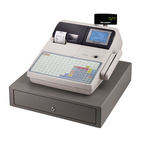
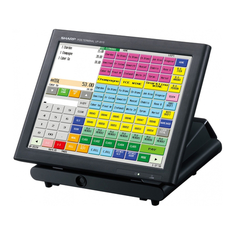
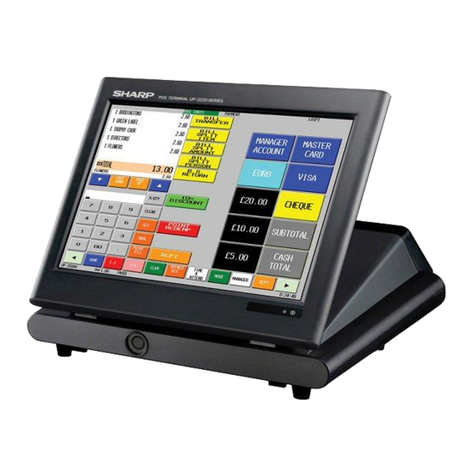
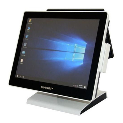
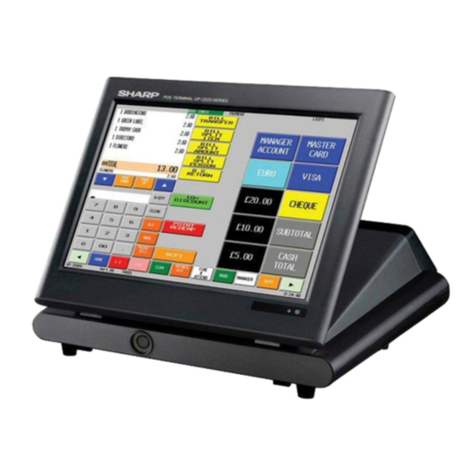
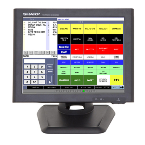
Sharp UP-600 Owner's manual

POS TERMINAL
MODEL UP-600
UP-700
(For "U" & "A" version)
CHAPTER 1. SRV. RESET AND MASTER RESET ........................................2
CHAPTER 2. READING OF SRV MODE PROGRAM .....................................3
CHAPTER 3. SRV MODE PROGRAMMING ("2 SETTING").........................10
CHAPTER 4. SRV MODE PROGRAMMING ("3 IRC SETTING")..................45
CHAPTER 5. SRV MODE PROGRAMMING ("4 DOWN LOAD")..................48
CHAPTER 6. SRV MODE PROGRAMMING ("5 DIAGNOSTICS")................49
For setting in PGM1 or PGM2 mode, refer to the Operation Manual.
CONTENTS
Parts marked with " " are important for maintaining the safety of the set. Be sure to replace these parts with specified
ones for maintaining the safety and performance of the set.
SHARP CORPORATION This document has been published to be used
for after sales service only.
The contents are subject to change without notice.
UP-600
UP-700

Major keys used in the SRV mode
The following major keys are used in the SRV mode.
FUNCTION KEY DESRIPTION
CURSOR UP Moves cursor up (1character)
CURSOR DOWN Moves cursor down (1character)
CURSOR RIGHT Moves cursor right (1character)
CURSOR LEFT Moves cursor left (1character)
PAGE UP PAGE UP Moves page up (1page)
PAGE DOWN PAGE DOWN Moves page up (1page)
CLEAR CL Clear numeric entry or error message
CANCEL CANCEL Operaation cancel & back to previouse menu.
ENTER ENTER Data entry
ALL ENTER TL All entry terminate.
TOGGLE SELECT Toggles between selections
SELECTABLE VALUE LIST ST Show selectable value
KYEBOARD LAYOUT
Key type
Number of keys
Key pitch
<Standard Key layout>
<Text Preset Key layout>
RECEIPT
JOURNAL
CANCEL
•
8
5
2
00
ENTER
CL
9
6
3
000
PAGE
DOWN
7
4
1
0
PAGE
UP
MISC
FUNC
100
86
99
85
98
84
97
83
70
96
82
69
95
81
68
47
37
27
94
80
67
57
46
36
26
17
93
79
66
56
45
35
25
16
8
92
78
65
55
44
34
24
15
7
91
77
64
53
43
33
23
14
6
90
76
63
53
CA/AT
Level
#
GLU
FINAL
(CANCEL)
(ENTER)
•CL
+
789
]
456
123
000 000
(PAGE
DOWN)
(Ins)
(PAGE
UP)
(BACK
SPACE)
RECEIPT
JOURNAL
}
[{
-
@/FOR
:
/
)
P
;
(
O
L
I
K
&
U
J
Y
H
%
T
G
$
R
F
#
E
D
.,
><
MNBVCXZ
( ) ( )
( )
( )
(DC)
(Del)
(NEXT
RECORD)
(PREV.
RECORD)
(Shift) (Space)
?
W
S
!
Q
A
’”
^=
Ñ¿
AUTO
1AUTO
2
TAX
SHIFT
RECEIPT
JOURNAL RCPT CASH# AMT
INQ
CANCEL
ENTER
•CL
510 15 20 FS
TEND
789
4 9 14 19
NS
456
381318
CHK# CH#
TAX 123
2 7 12 17
RFND
000
161116
CA/AT
AUTO
2
PRICE
CHANGE
PLU/UPC
PAGE
DOWN
PAGE
UP
MISC
FUNC
VOID
#/TM
TAX
SHIFT
CONV#
@/FOR
AUTO
1
FS
SHIFT
NEXT$
MDSE
SBTL
SBTL
(CANCEL)
CL
A
FK
P
U
X
BG
L
Q
V
Y
CH
M
R
W
Z
(ENTER)
DI
N
S
EJ
O
T
•
9
6
3
8
5
2
00
7
4
1
0
(SPACE)
( )
( ) ( )
(PAGE
DOWN)
(PAGE
UP)
RECEIPT
JOURNAL
( )
CA/AT
(DC)
@/FOR
SBTL
(SHIFT)
(RECALL)
(UPDATE)
(NEXT
RECORD)
(PREV
RECORD)
(DEL)
(INS)
(BACK
SPACE)
42
32
22
13
5
89
75
62
52
41
31
21
12
4
88
74
61
51
40
30
20
11
3
87
73
60
50
39
29
19
10
2
72
59
49
38
28
18
9
1
71
58
48
SERV#
RCPT VOID
@/
For
RFND CONV
#
P-SHIFT
#
SRVC
SBTL
PLU/
SUB
CR#
CHK#
CA/ATSBTL
(Recall)
(UPDATE)
(Space) (Space) (Space) (Space)
@
<Text Preset Key layout>
: Normal type
: STD 9key
: MAX 84key
: 19mm(w) x 19mm(h)
Key type
Number of keys
Key pitch
: Flat type
: STD 144key (16 x 9)
: MAX 144key
: 18mm(w) x 15mm(h)
>>>>> USE FONT <<<<<
Helvetica/ Helvetica-Condensed/ Century-Schoolbook/ Symbol & OriginalFonts: (RingWorld2/RingFont2/Pa
Symbol/PartsCod)
- - - - - - - - - - - - - - - - - - - - - - - - - - - - - - - - - - - - - - - - - - - - - - - - - - - - - - -

CHAPTER 1. SRV. RESET AND MASTER RESET
The SRV key is used for operating in the SRV mode.
1. SRV. RESET (Program Loop Reset)
Used to return the machine back to its operational state after a lock-
up has occurred.
Procedure
•Method 1
1) Turn off the AC switch.
2) Set the mode switch to (SRV’) position.
3) Turn on the AC switch.
4) Turn to (SRV) position from (SRV’) position.
•Method 2
1) Set the mode switch to PGM2 position.
2) Turn off the AC switch.
3) While holding down JOURNAL FEED key and RECEIPT FEED
key, turn on the AC switch.
Note: When disassembling and reassembling always power up us-
ing method 1 only. Method 2 will not reset the CKDC9.
Note: SRV programming job#926-B must be set to "4" to allow PGM
program loop reset.
PRG. RESET
2. MASTER RESET (All memory clear)
There are three possible methods to perform a master reset.
MRS-1 (Master resetting 1)
Used to clear all memory contents and return machine back to its
initial settings.
Return keyboard back to default. for default key-board layout.
Procedure
1) Turn off the AC switch.
2) Set the MODE switch to the (SRV’) position.
3) Turn on the AC switch.
4) While holding down JOURNAL FEED key, turn to (SRV) posi-
tion from (SRV’) position.
MRS-2 (Master resetting 2)
Used to clear all memory and keyboard contents.
This reset returns all programming back to defaults. The keyboard
must be entered by hand.
This reset is used if an application needs different keyboard layout
other than that supplied by a normal MRS-1.
Procedure
1) Turn off the AC switch.
2) Set the MODE switch to the (SRV’) position.
3) Turn on the AC switch.
4) While holding down JOURNAL FEED key and RECEIPT FEED
key, turn to (SRV) position from (SRV’) position.
5) Key position assignment:
After the execution of MRS-2, only the RECEIPT FEED and
JOURNAL FEED keys can remain effective on key assignment.
Any key can be assigned on any key position on the main key-
board.
[key setup procedure]
MASTER RESET
NOTES:
*1: When the 0 key is pressed, the key of the key number on
display is disabled.
*2: Push the key on the position to be assigned. With this, the key
of the key number on display is assigned to that key position.
*3: When relocating the keyboard, the PGM 1/2 mode use stand-
ard key layout.
Key
No. Key
name Key
No. Key
name Key
No. Key
name
001 011 021
002 012 022
003 013 023
004 014
005 015
006 016
007 017
008 018
009 019
010 020
MRS-2 executed Key position set Free key
Disable
Free key setup
complete.
*2
*1
0
0
MRS-3 (Master resetting 3)
Master resetting 3 requires the entry of Serial No. data in addition to
Master resetting 1.
After completion of the MRS-3, the following operations and program-
ming will be inhibited.
1. GT programming.
2. All memory download via RS-232.
3. GT resets with Z report. (Z report can be made, but GT will not be
reset.)
Procedure
1) Turn off the AC switch.
2) Set the reset switch to the "SRV" position.
3) Turn on the AC switch.
4) While holding down the JOURNAL FEED key and MRS-3 key,
turn to (SRV) position from (SRV’) position.
MRS-3 key : UP-600=[CANCEL] key
UP-700=[PLU70] key
5) The product serial No. input window is displayed as shown
below.
DISPLAY:
Enter the product serial No. of this POS and enter the [CA/AT]
key.
6) Key position assignment:
After the execution of MRS-2, only the RECEIPT FEED and
JOURNAL FEED keys can remain effective on key assignment.
Any key can be assigned on any key position on the main key-
board.
[key setup procedure]
MASTER RESET
NOTES:
*1: When the 0 key is pressed, the key of the key number on
display is disabled.
*2: Push the key on the position to be assigned. With this, the key
of the key number on display is assigned to that key position.
*3: When relocating the keyboard, the PGM 1/2 mode use stand-
ard key layout.
Key
No. Key
name Key
No. Key
name Key
No. Key
name
001 011 021
002 012 022
003 013 023
004 014
005 015
006 016
007 017
008 018
009 019
010 020
SERIAN No. 00000000
MRS-2 executed Key position set Free key
Disable
Free key setup
complete.
*2
*1
0
0
>>>>> USE FONT <<<<<
Helvetica/ Helvetica-Condensed/ Century-Schoolbook/ Symbol & OriginalFonts: (RingWorld2/RingFont2/Pa
Symbol/PartsCod)
- - - - - - - - - - - - - - - - - - - - - - - - - - - - - - - - - - - - - - - - - - - - - - - - - - - - - - -

CHAPTER 2. READING OF SRV MODE PROGRAM
The setting contents of the SRV mode can be checked with the
printer
DISPLAY: SRV mode screen
Select "1 READING " and press the Enter key.
DISPLAY: READING item selection screen
Select the desired item, press the Enter key.
The setting content is printed.
Sample of program reports
1. [1 SYSTEM PRESET]
•UP-600

•UP-700 2. [2 DEVICE CONFIG]
•UP-600
•UP-700
Report title
Device name / Not assigned
Report title
Device name / Not assigned

3. [3 FREE KEY]
•UP-600
Report title
Key No. / Key text /
Not assigned
Key No. / Key text /
Key position code

•UP-700
Report title
Key No. / Key text /
Not assigned
Key No. / Key text /
Key position code

4. [4 FILE]
•UP-600
Report title
File table No. / No. of records/
No. of used records
File table No. / No. of records /
No. of blocks / No. of used
records
File memory start address
Empty memory start address
Memory end address

•UP-700
Report title
File table No. / No. of records/
No. of used records
File table No. / No. of records /
No. of blocks / No. of used
records
File memory start address
Empty memory start address
Memory end address

5. [5 SSP]
•UP-600
•UP-700

CHAPTER 3. SRV MODE PROGRAMMING ( "2 SETTING")
DISPLAY: SRV mode screen
Select " 2 SETTING " and press the Enter key.
DISPLAY: SETTING item selection screen
Select the desired item, press the Enter key.
The item setting input screen is displayed.
1. [01 DEVICE CONFIG]
DISPLAY: DEVICE CONFIG select screen
Select the item to be changed and press the ENTER key.
The setting input screen is displayed.

[01 DEVICE CONFIG] - [01 R/J PRINTER] DISPLAY: Setting screen
[R/J PRINTER] (Built-in printer programming)
DISPLAY CONTENTS SELECT ITEM MRS NOTE
LIGHT&SHADE Light & shade of printing 00-99 50 00= 75% for standard
50= 100% <Standard>
99= 125% for standard
IMAGE FOOTER Footer Graphic LOGO print NOT PRINT NOT PRINT
PRINT
PRINT Buffering print BUFFERING BUFFERING BUFFERING :
The recipt prints the recapitulated data at the finalization
of transaction. The journal prints the non-recapitulated
data at the finalization of transaction.
REAL TIME REAL TIME :
Both receipt and journal print each data at same time
when each registration is operated.
TRAY ST FEED# Tray ST feed line 0-9 0 Only Receipt printer’s programming
[01 DEVICE CONFIG] - [02 BILL (SLIP)] DISPLAY: Setting screen
[BILL (SLIP)]
DISPLAY CONTENTS SELECT ITEM MRS NOTE
TERMINAL# Terminal No. 000-254 000 000 : Self terminal No.
This means local device.
1-254: Except self terminal No.
This means re-routed device.
Re-routing programming is only valid for printer.
CHANNEL# Channel No. 0-7 0 0: No RS232 channel is assigned.
1-7: RS232 channel is assigned.
PRINTER Connected printer name TM-295 TM-295
TM-T88/85
TM-U210
TM-T80
TM-T88 (2)
TM-300
AUTO CUTTER Auto cutter function No No This item is not valid only for TM-295.
Yes
INITIAL FEED# Initial SLIP feed line number 00-64 00
SLIP MAX LINE Slip print maximum line No. 00-99 99
>>>>> USE FONT <<<<<
Helvetica/ Helvetica-Condensed/ Century-Schoolbook/ Symbol & OriginalFonts: (RingWorld2/RingFont2/Pa
Symbol/PartsCod)
- - - - - - - - - - - - - - - - - - - - - - - - - - - - - - - - - - - - - - - - - - - - - - - - - - - - - - -

[01 DEVICE CONFIG] - [03 REPORT PRINTER] DISPLAY: Setting screen
[REPORT PRINTER]
DISPLAY CONTENTS SELECT ITEM MRS NOTE
TERMINAL# Terminal No. 000-254 000 000 : Self terminal No. This means local device.
1-254 : Except self terminal No. This means
re-routed device.
Re-routing programming is only valid for printer.
CHANNEL# Channel No. 0-7 0 0 : No RS232 channel is assigned.
1-7 : RS232 channel is assigned.
PRINTER Connected printer name BUILT-IN BUILT-IN In case of "BUILT-IN":
The printing method is according to "R/J
PRINTER" programming. (AUTO CUTTER and
LOGO are used the programming data of
"REPORT PRINTER)
TM-T80
TM-T88/85
TM-300
TM-U210
TM-T88 (2)
AUTO CUTTER Aito cutter function NO NO
YES
LOGO TEXT Logo text print PRINT PRINT
NOT PRINT
[01 DEVICE CONFIG] - [04 VALIDATION (VP)] DISPLAY: Setting screen
[VALIDATION (VP)]
DISPLAY CONTENTS SELECT ITEM MRS NOTE
TERMINAL# Terminal No. 000-254 000 000 : Self terminal No. This means local device.
1-254 : Except self terminal No. This means
re-routed device.
Re-routing programming is only valid for printer.
CHANNEL# Channel No. 0-7 0 0 : No RS232 channel is assigned.
1-7 : RS232 channel is assigned.
PRINTER Connected printer name BUILT-IN BUILT-IN
(UP-600) The UP-700 can not be selected "BUILT-IN".
(Fixed at "TM-295)
TM-295 TM-295
(UP-700)
VP TIMES No. of times of VP 0-9 1 This item is valid only for TM-295
YES

[01 DEVICE CONFIG] - [05 KP#1] / [06 KP#2] / [07 KP#3]
[08 KP#4] / [09 KP#5] / [10 KP#6]
[11 KP#7] / [12 KP#8] / [13 KP#9]
DISPLAY: Setting screen
[KITCHEN PRINTER] KP#1-KP#9
DISPLAY CONTENTS SELECT ITEM MRS NOTE
TERMINAL# Terminal No. 000-254 000 000 : Self terminal No.
This means local device.
1-254: Except self terminal No.
This means re-routed device.
The built-in printer cannot be re-routed.
Re-routing programming is only valid for printer.
CHANNEL# Channel No. 0-7 0 0: No RS232 channel is assigned.
1-7: RS232 channel is assigned.
PRINTER Connected printer name TM-T88/85 TM-T88/85 In case of "BUILT-IN" :
The printing method is according to "R/J
PRINTER" programming. (AUTO CUTTER and
LOGO are used the programming data of
"REPORT PRINTER)
TM-300
TM-U210
TM-T88 (2)
BUILT-IN
TM-T80
AUTO CUTTER Aito cutter function NO NO
YES
LOGO TEXT Logo text print PRINT PRINT Logo text and its format is same as Receipt.
If a printer is set as "TM-T88 (2) ", its STAMP
can be printed.
NOT PRINT

[01 DEVICE CONFIG] - [14 CAT#1]/[15 CAT#2] DISPLAY: Setting screen
[CAT#1,CAT#2]
DISPLAY CONTENTS SELECT ITEM MRS NOTE
TERMINAL# Terminal No. 000-254 000 000 :Self terminal No.
This means local device.
1-254 : Except self terminal No.
CHANNEL# Channel No. 0-7 0 0 : No RS232 channel is assigned.
1-7 : RS232 channel is assigned.
[01 DEVICE CONFIG] - [16 ITC] DISPLAY: Setting screen
[ITC]
DISPLAY CONTENTS SELECT ITEM MRS NOTE
CHANNEL# Channel No. 0-7 0 0 : No RS232 channel is assigned.
1-7 : RS232 channel is assigned.

[01 DEVICE CONFIG] - [17 BCR(SCANNER)] DISPLAY: Setting screen
[BCR (SCANNER)]
DISPLAY CONTENTS SELECT ITEM MRS NOTE
CHANNEL# Channel No. 0-7 0 0: No RS232 channel is assigned.
1-7: RS232 channel is assigned.
BAUD RATE Transmission speed 4800 bps 4800 bps
9600 bps
19200 bps
DATA BITS Data bit 7 Bits 7 Bits
8 Bits
PARITY Parity bit ODD ODD
EVEN
NON
STOP BIT Stop bit 1 Bits 1 Bit
2 Bit
ER-A6HS1 setting : "BAUD RATE = 4800 bps" , "DATA BITS = 7Bits", "PARITY = ODD", "STOP BIT = 1Bit"
NOTE: 1. Set the channel No. so that it does not conflict with other devices that are to be connected. If it does, the unit won’t operate normally.
2. Do not use channel No. 2 for the ER-A6HS1. Use other channel Nos.
3. If you want to change the channel No. of the BCR (Scanner), set a channel No. that is other than 0 and does not conflict with other
devices.
[01 DEVICE CONFIG] - [18 SCALE] DISPLAY: Setting screen
[SCALE]
DISPLAY CONTENTS SELECT ITEM MRS NOTE
CHANNEL# Channel No. 0-7 0 0: No RS232 channel is assigned.
1-7: RS232 channel is assigned.
NOTE: 1. Set the channel No. so that it does not conflict with other devices that are to be connected. If it does, the unit won’t operate normally.

[01 DEVICE CONFIG] - [19 COIN DISP.] DISPLAY: Setting screen
[COIN DISPENSER]
DISPLAY CONTENTS SELECT ITEM MRS NOTE
CHANNEL# Channel No. 0-7 0 0 : No RS232 channel is assigned.
1-7 : RS232 channel is assigned.
[01 DEVICE CONFIG] - [20 ONLINE] DISPLAY: Setting screen
[ONLINE]
DISPLAY CONTENTS SELECT ITEM MRS NOTE
CHANNEL# Channel No. 0-7 0 0: No RS232 channel is assigned.
1-7: RS232 channel is assigned.
NOTE: 1. Set the channel No. so that it does not conflict with other devices that are to be connected. If it does, the unit won’t operate normally.
2. Do not use channel No. 2 for the modem. Use other channel Nos.
[01 DEVICE CONFIG] - [21 CVM DATA I/F] DISPLAY: Setting screen
[CVM DATA I/F]
DISPLAY CONTENTS SELECT ITEM MRS NOTE
TERMINAL# Terminal No. 000-254 000 000 : Self terminal No.
This means local device.
1-254 : Except self terminal No.
CHANNEL# Channel No. 0-7 0 0 : No RS232 channel is assigned.
1-7 : RS232 channel is assigned.

2. [02 SYSTEM PRESET]
DISPLAY: Setting item select screen
Select "02 SYSTEM PRESET" and press the ENTER key.
DISPLAY: SYSTEM PRESET screen
Select the JOB# to be changed and enter the value.
The content of each JOB# is described below.

[JOB#901] : UP-600/700 MRS=0002
Note : ★... MRS for UP-600
✩ ... MRS for UP-700
901-A: Not used (Fixed at "0")
901-B: 1. Tax system
1. Tax system 901-B
Auto tax 1-4 & Manual tax 0 ★✩
CANADIAN TAX (Type1 to Type 10) 6
CANADIAN TAX (Type 11) 7
901-C: 1.Rounding system
1.Rounding system 901-C
Normal 0 ★✩
Singapole 8
901-D: 1.TAB setting
1.TAB setting 901-D
0 0
0.0 1
0.00 2 ★✩
0.000 3
[JOB#902] : UP-600 MRS=0050
UP-700 MRS=0000
902-A: 1.In-line system
1.In-line system 902-A
No 0 ★✩
Yes 1
902-B: Not used (Fixed at "0")
902-C: 1. Display format of operator display (LCD).
2. Clerk report format
1. Display format of
operator display (LCD). 2. Clerk report format 902-C
GLU mode Type 1 (SERVER) 0 ✩
Type 2 (CASHIER) 1
CHECK OUT mode Type 1 (SERVER) 4
Type 2 (CASHIER) 5 ★
[JOB#903] : UP-600 MRS=8003
UP-700 MRS=8000
903-A: 1. POS data copy baud rate
1. Baud rate 903-A
2400 2
4800 3
9600 4
19200 5
38400 6
57600 7
115200 8 ★✩
903-B: 1. Symbol of scale entry
1. Symbol of scale entry 903-B
"LB" 0 ★✩
"KG" 2
903-C: 1. Entry of tare
2. Unit of weight for the scale
1. Entry of tare 2. Unit of weight for the
scale 903-C
Disallowed 2id(3id)+2dd 0 ★✩
1id(2id)+3dd 1
Allowed 2id(3id)+2dd 2
1id(2id)+3dd 3
903-D: 1. Food stamp
1. Food stamp 903-D
No Food stamp 0 ✩
Tax not payable in Food stamp 1
Tax payable in Food stamp 2
Food stamp forgiveness 3 ★
[JOB#904] : UP-600/700 MRS=0000
904-A: 1. Printing of date
2. Fraction treatment at gasoline (OIL) q’ty calculation
1. Printing of date 2. Fraction treatment at
gasoline (OIL) q’ty
calculation 904-A
Yes Round off 0 ★✩
Round up 1
Round down 2
No Round off 4
Round up 5
Round down 6
904-B: 1. Printing of the consecutive No.
2. Decimal point position of gasoline (OIL) q’ty
1. Printing of the
consecutive No. 2. Decimal point position of
gasoline (OIL) q’ty 904-B
Yes
0 0 ★✩
0.0 1
0.00 2
0.000 3
No
0 4
0.0 5
0.00 6
0.000 7
Note : ★...MRS for UP-600 / ✩...MRS for UP-700
Other manuals for UP-600
9
This manual suits for next models
1
Table of contents
Other Sharp Touch Terminal manuals

Sharp
Sharp UP-5700 User manual

Sharp
Sharp ER-A770 User manual

Sharp
Sharp UP-5300 User manual

Sharp
Sharp UP-600 User manual

Sharp
Sharp UP-3500 User manual

Sharp
Sharp UP-3300 Owner's manual

Sharp
Sharp UP-X500 User manual

Sharp
Sharp UP-3300 Owner's manual

Sharp
Sharp ER-A770 User manual

Sharp
Sharp UP-3500 User manual

Sharp
Sharp ER-A771 User manual

Sharp
Sharp UP-600D Configuration guide

Sharp
Sharp UP-600 User manual

Sharp
Sharp UP-3500 User manual

Sharp
Sharp UP-X300 User manual

Sharp
Sharp UP-X300CF256 User manual

Sharp
Sharp ER-A850 User manual

Sharp
Sharp UP-3301 Owner's manual

Sharp
Sharp UP-5300 User manual

Sharp
Sharp UP-V5500 User manual