2113542 Revision date: 09.21.18
READ THIS DOCUMENT BEFORE YOU BEGIN
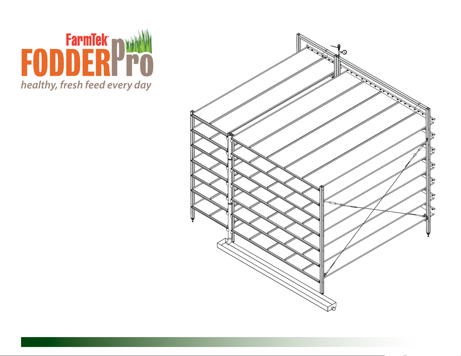
Thank you for purchasing the FodderPro 3.0 Commercial Feed Module. When properly assembled and maintained, this system will provide years of reliable
service. This guide includes information needed to safely assemble and maintain the system. Read these instructions before you begin.
Important Information
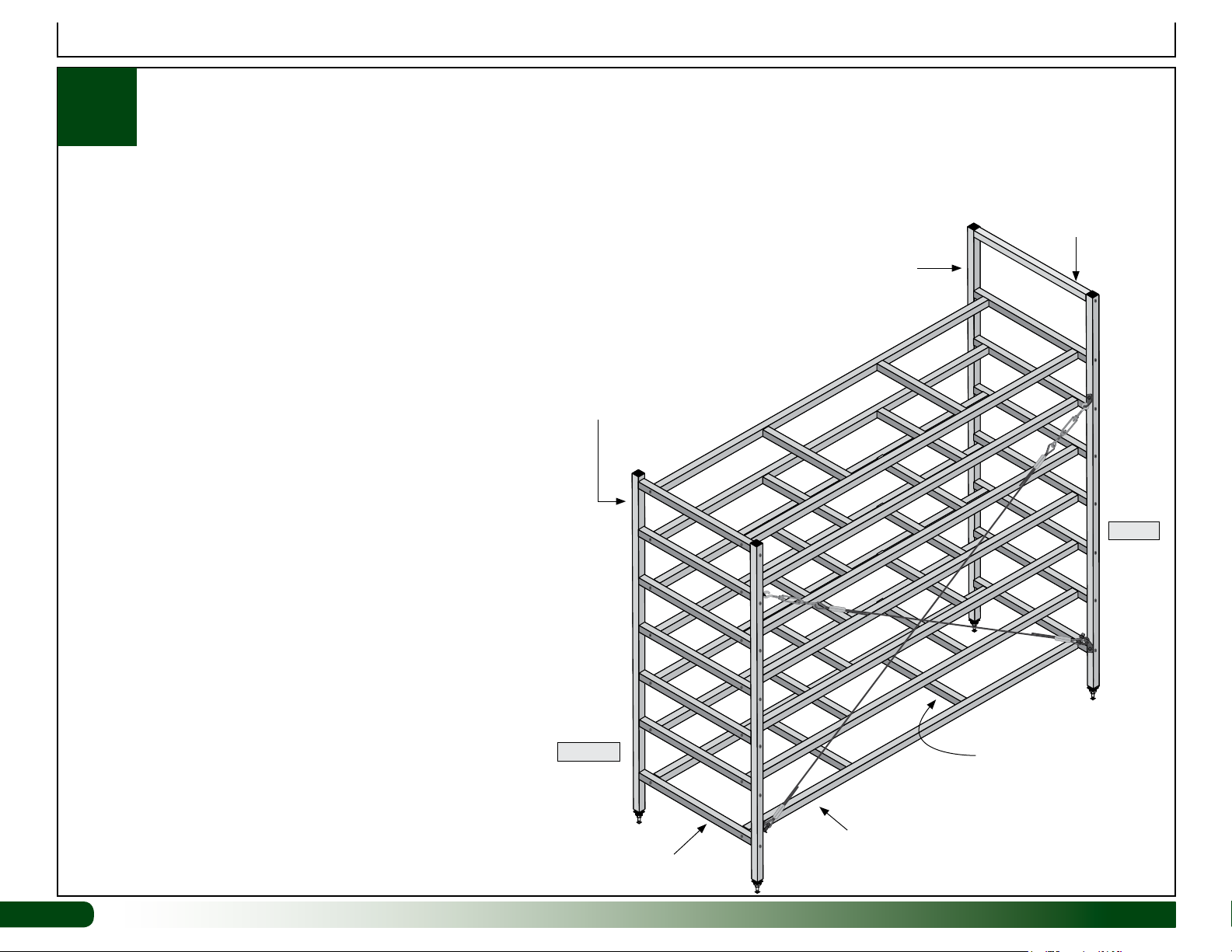
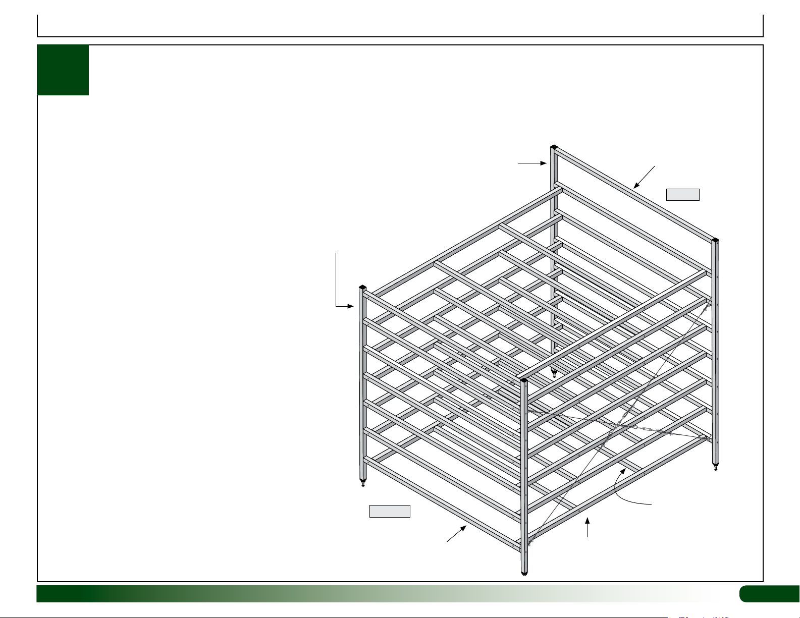
ASSEMBLY PROCEDURE
This manual describes how to assemble the
113542 FodderPro 3.0 system. The steps outlining
the assembly process are as follows:
1. Unpack the contents of the shipment and
place where you can easily inventory the
parts. Refer to the Bill of Materials/Spec
Sheets.
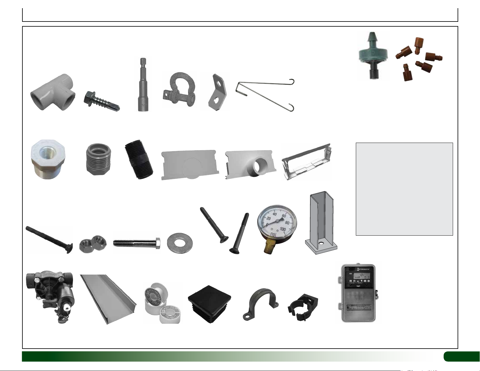
2. Verify that all parts listed on the Bill of
Materials/Spec Sheets are present. If anything
is missing or you have questions, consult
the Pictorial Parts Guide and all diagrams for
clarification, or contact Customer Service.
3. Read and understand these instructions and
all additional documentation included with the
shipment before you begin.
4. Gather the required tools.
5. For best results, assemble the components
in the order they are presented in these
instructions.
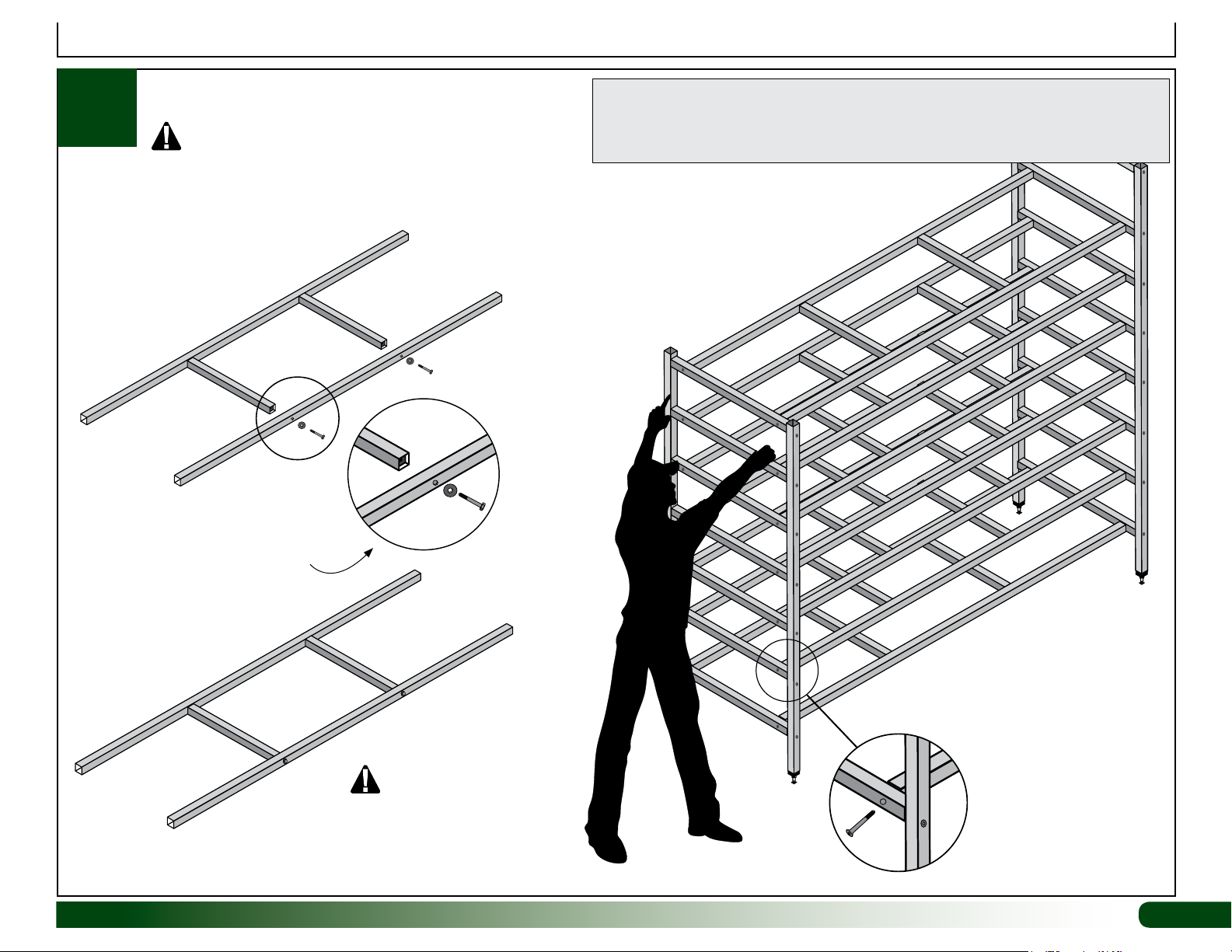
SAFETY PRECAUTIONS
• Wear eye protection.
• Wear gloves when handling metal tubes.
• Use a portable GFCI (Ground Fault Circuit
Interrupter) when working with electric power
tools and cords.
ELECTRICAL WARNING!
Fodder frame is metal and will conduct
electricity! Exercise caution if working around
or on the frame with electric power tools. Use
cordless, battery-power tools.
CONSULT THE SERVICES OF A QUALIFIED
ELECTRICAL TECHNICIAN WHEN
INSTALLING TIMERS, ARTIFICIAL LIGHTING,
OR OTHER ELECTRICALLY POWERED
ACCESSORIES.
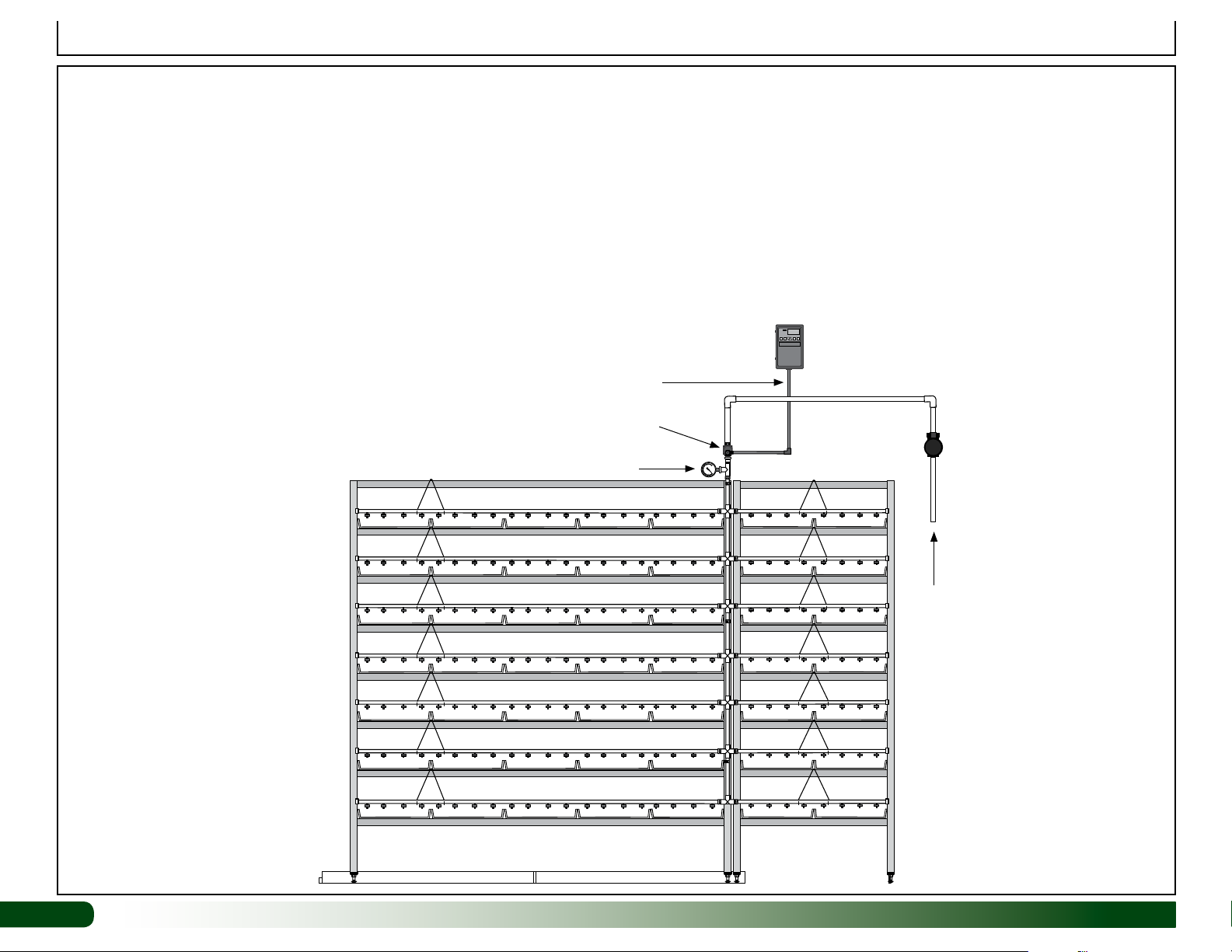
OPEN SYSTEM
The FodderPro 3.0 Commercial Feed System
is an open system; the water is not recycled
for use in the fodder system. The open system
requires a water source and a drain, or waste
water reservoir to accept the unused water.
This water can be recycled for use in other
applications such as watering other plants.
However, to promote healthy fodder growth,
it is not recommended for reuse in the fodder
system.
IMPORTANT: Have the water tested before
feeding it to any livestock.
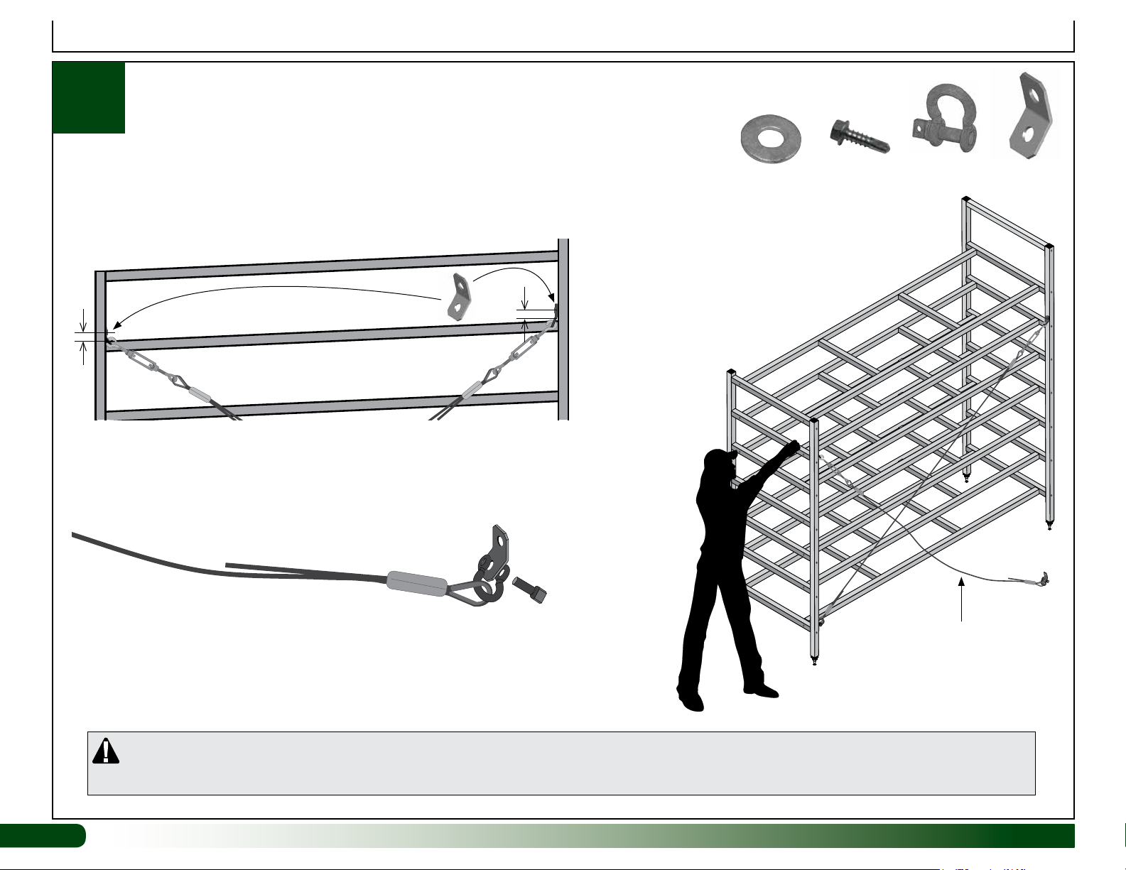
CAUTION!
DO NOT CLIMB ON FRAME!
TO PREVENT INJURY AND POSSIBLE
DAMAGE TO THE FODDER SYSTEM AND
RELATED COMPONENTS, NEVER CLIMB
ON THE ASSEMBLED OR PARTIALLY
ASSEMBLED FRAME.
NEVER USE THE FRAME ENDS AS A
LADDER TO REACH THE UPPER LEVEL OF
THE FODDER FRAME!
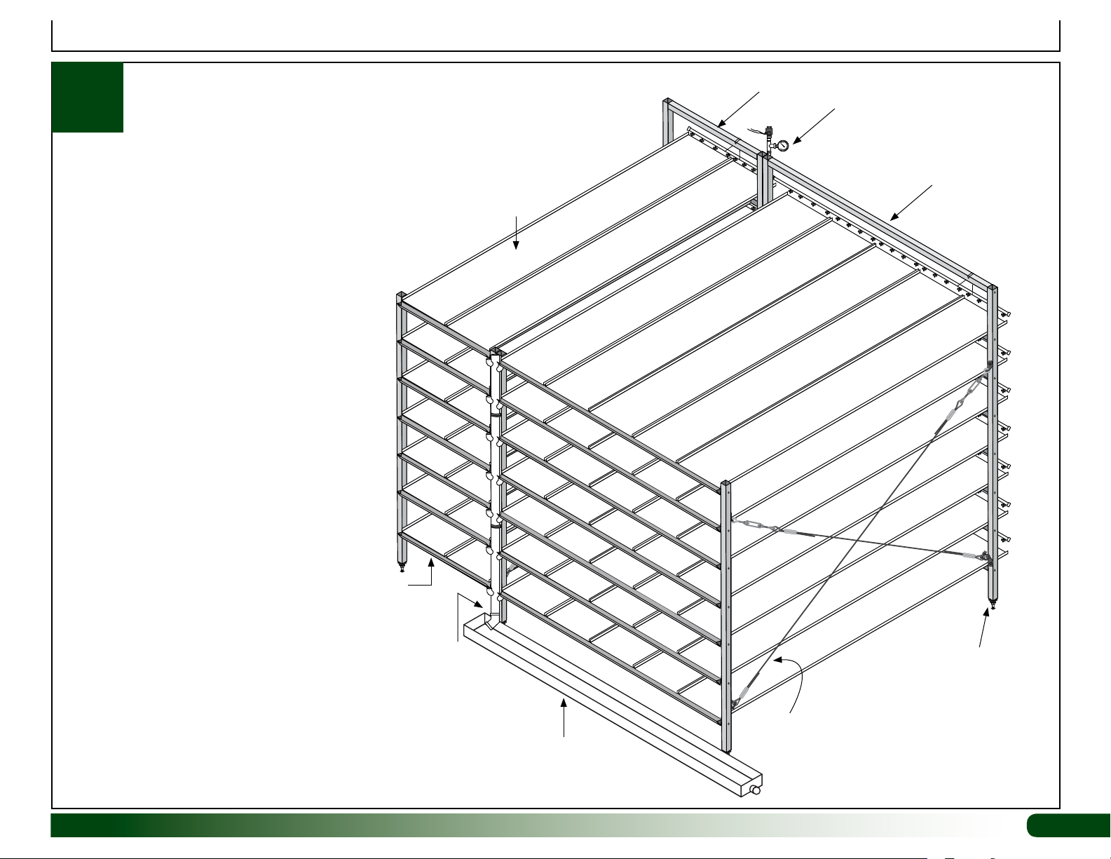
ATTENTION: CONSULT ALL DIAGRAMS AND
THOSE NEAR THE BACK OF THIS GUIDE
TO IDENTIFY CRITICAL DIMENSIONS, PART
NUMBERS, AND PART LOCATIONS FOR YOUR
COMMERCIAL FODDER SYSTEM.
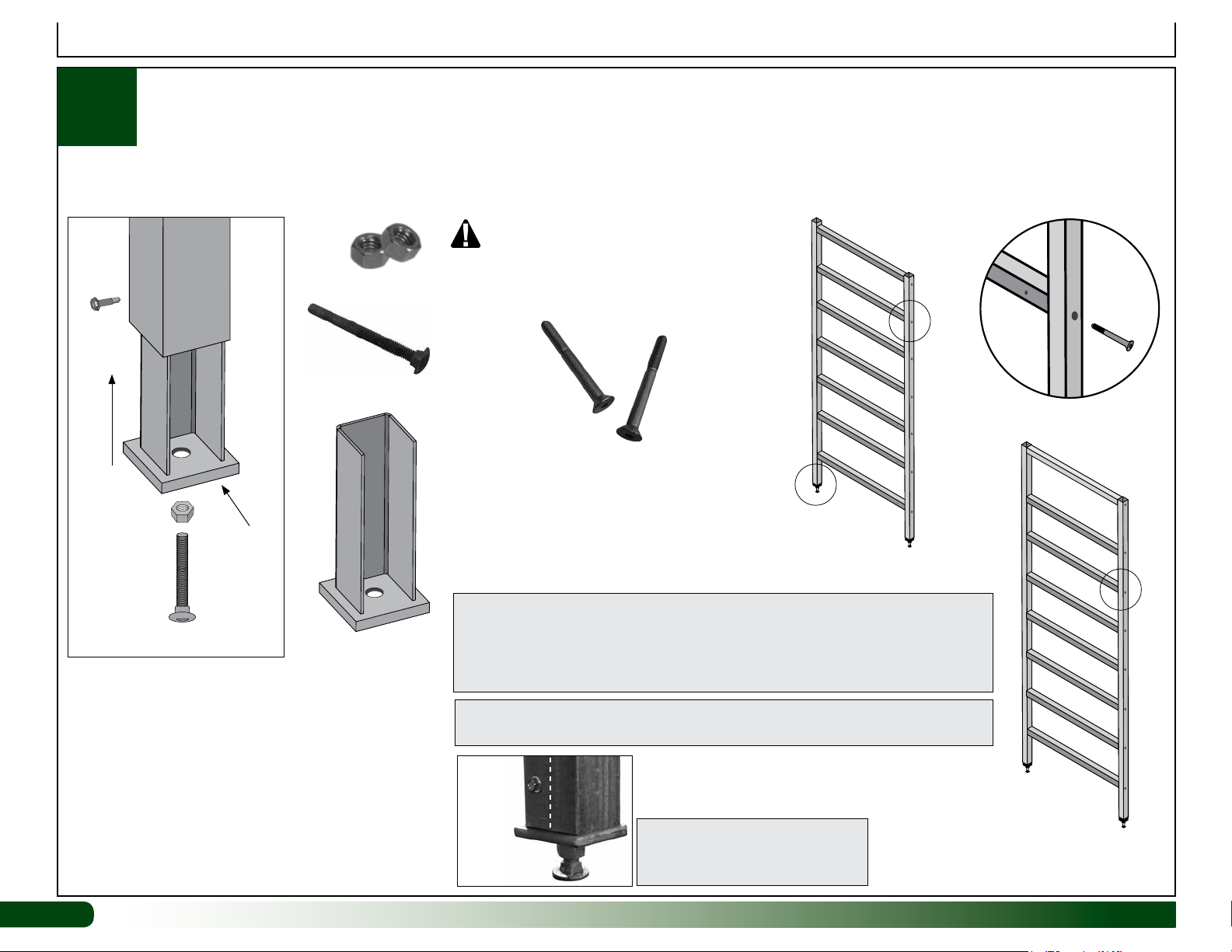
REQUIRED TOOLS
The following list identifies the main tools needed to
assemble the fodder system. Additional tools and
supports may be needed.
• Tape measure and marker
• Variable speed drill to drive Tek screws
• Levels: 2' and 4'
• Wrench set or ratchet with 1/2" socket to
assemble frame
• 3/16" hex (Allen) wrench—preferably one that
can be used in a socket to operate with a drill.
• Adjustable pliers and small hammer
• Ladder or work platform to work at the height of
the fodder system frame.