2111628E Revision date: 02.16.23
READ THIS DOCUMENT BEFORE YOU BEGIN
Thank you for purchasing the 111628E FodderPro 2.0 Full Feed System. When properly assembled and maintained, this product will provide years of reliable
service. This guide includes important information needed to safely assemble and maintain the system. Please read these instructions before you begin.
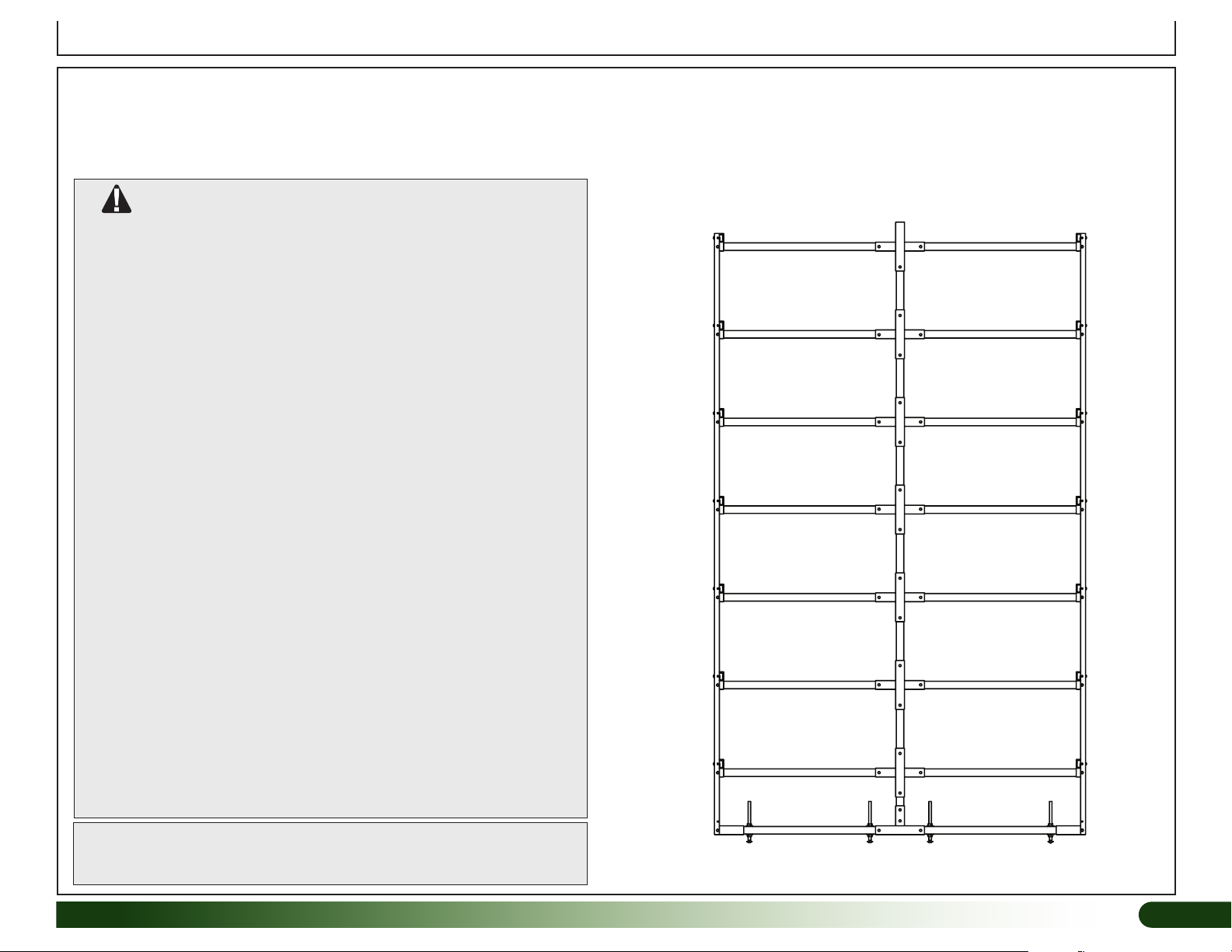
ASSEMBLY PROCEDURE
Following the instructions as presented will
help ensure the proper assembly of your fodder
system. This manual describes how to assemble a
single 111628E FodderPro 2.0 Full Feed
System — Expanded.
The steps outlining the assembly process are as
follows:
1. Verify that all parts are included in the
shipment. Notify customer service for
questions or concerns.
2. Read these instructions and all additional
documentation included with the shipment
before you begin.
3. Gather the tools and assistants.
4. For best results, assemble the components
in the order they are presented in these
instructions.
Important Information
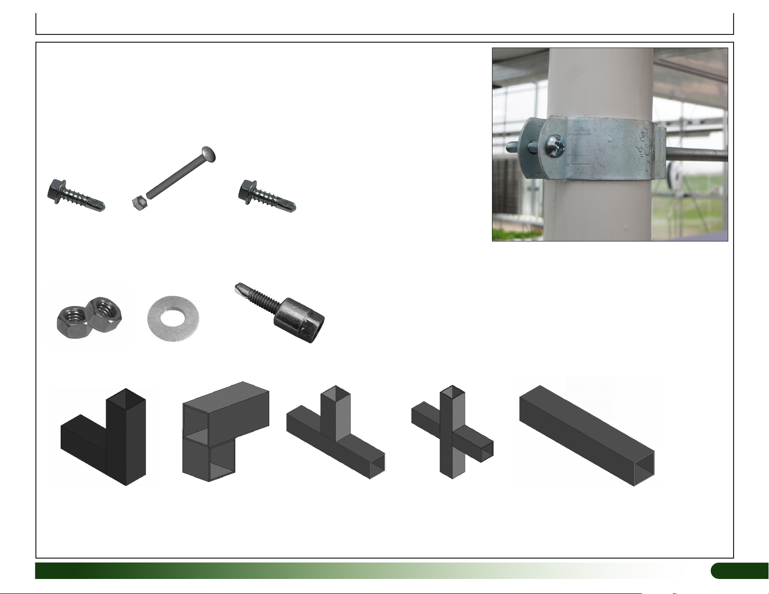
UNPACK AND IDENTIFY PARTS
The following steps will ensure that you have all
the necessary parts before you begin assembly.
1. Unpack the contents of the shipment and
place where you can easily inventory the
parts. Refer to the Bill of Materials/Spec
Sheets.
2. Verify that all parts listed on the Bill of
Materials/Spec Sheets are present. If anything
is missing or you have questions, consult
the Pictorial Parts Guide and all diagrams for
clarification, or contact Customer Service.
QUICK START GUIDE
For a quick overview of this product and its
components, consult the Quick Start Guide at the
back of these instructions.
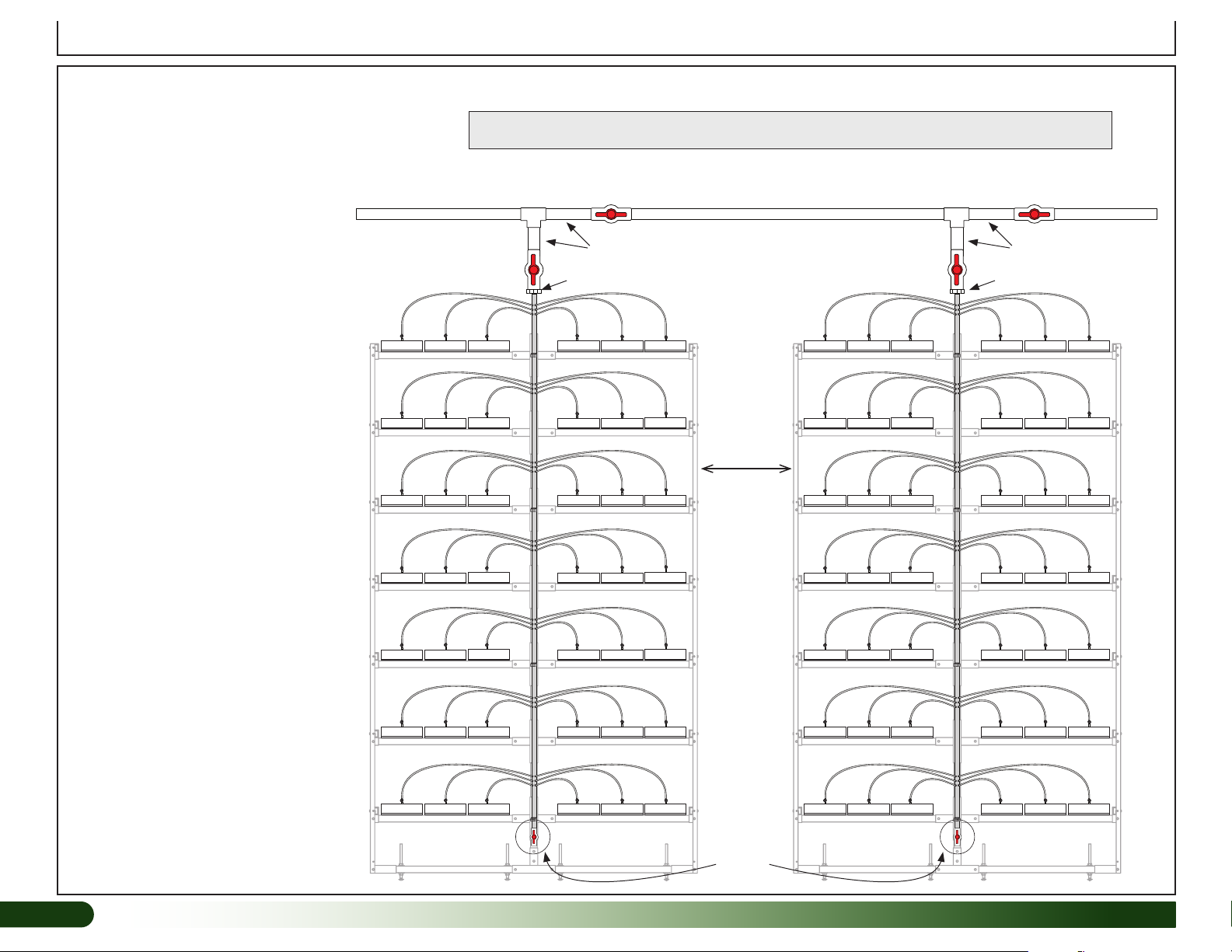
ATTENTION: This manual describes how to
assemble one 111628E FodderPro 2.0 Full Feed
System — Expanded. If you are connecting this
system to another, minor adjustments must be
made to some of the procedures that follow.
Consult the diagram on Page 4 for additional
details regarding multiple systems.
ELECTRICAL WARNING
Fodder frame is metal and will conduct electricity!
Exercise caution if working around or on the
frame with electric power tools. Use cordless,
battery-power tools.
CONSULT THE SERVICES OF A QUALIFIED
ELECTRICAL TECHNICIAN WHEN INSTALLING
ANY PUMPS, ARTIFICIAL LIGHTING,
OR OTHER ELECTRICALLY POWERED
ACCESSORIES.
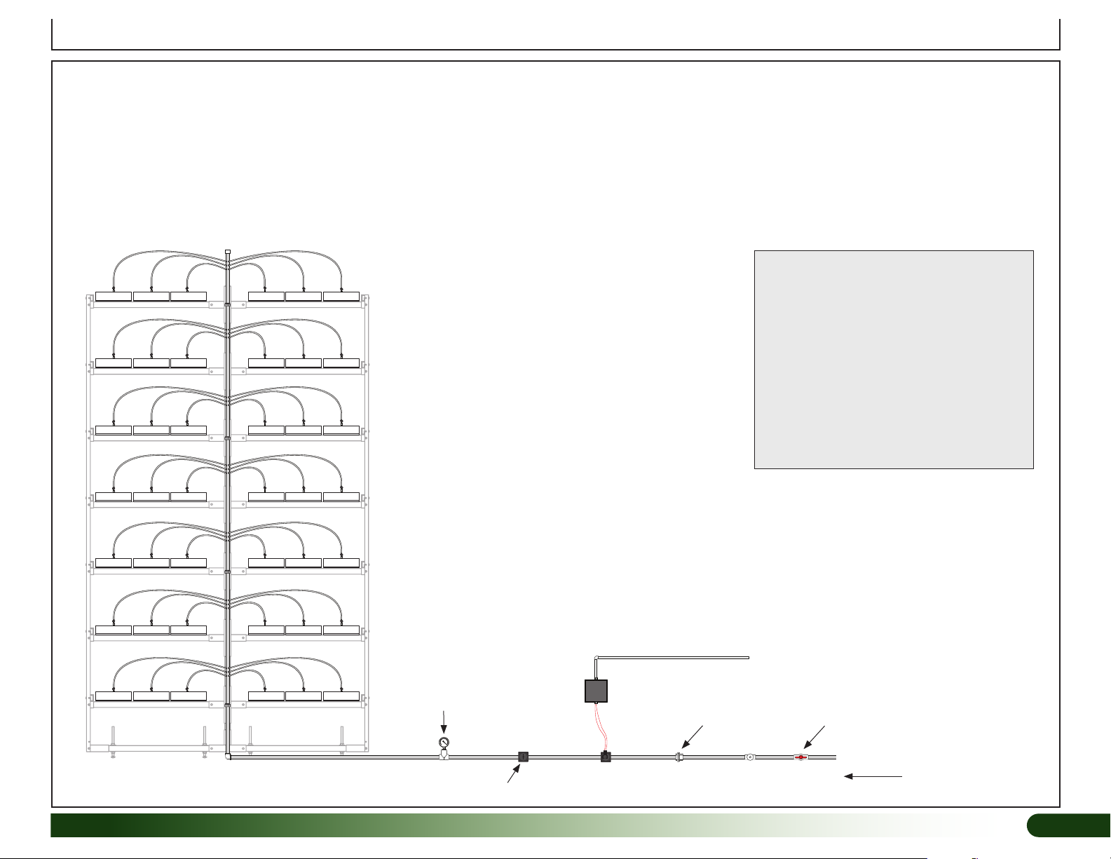
OPEN SYSTEM
The 111628E FodderPro 2.0 Full Feed System
is an open system, which means that the water
is not recycled for use in the fodder system.
Unlike a closed system where the water is
stored in a reservoir and recycled, the open
system requires a water source and a drain to
accept the unused water. The unused water can
be recycled for use in other applications such
as watering other plants; however, to promote
healthy fodder growth, it is not recommended
for reuse in the fodder system.
REQUIRED TOOLS
The following list identifies the main tools needed to
assemble the fodder system. Additional tools and
supports may be needed.
• Tape measure and marker
• Variable speed drill (cordless with extra batteries
works best) and drill bit set with a 9/32" & 7/16" bit.
• Small hammer and gloves
• PVC Tube Cutting Tool
• Level 4' (or longer)
• Wrench set or adjustable wrenches
• Socket Set with Ratchet
• Straight Screw Driver
• 1-3/8" hole saw bit for the drain manifold
• Adjustable pliers
• 5/8" nut driver (or 5/8" socket)
• Ladder or work platform to work at the height of
the fodder system frame.
SAFETY PRECAUTIONS
• Wear eye protection.
• Wear gloves when handling metal tubes.
• Use a portable GFCI (Ground Fault Circuit
Interrupter) when working with electric power tools
and cords.