Faro EVA User manual


EVA USER MANUAL - EN
Edition 1.0 April 2020 Pag. 2 di 14
TABLE OF CONTENTS
1SYMBOLS USED .........................................................................................................................................................................................................................................................3
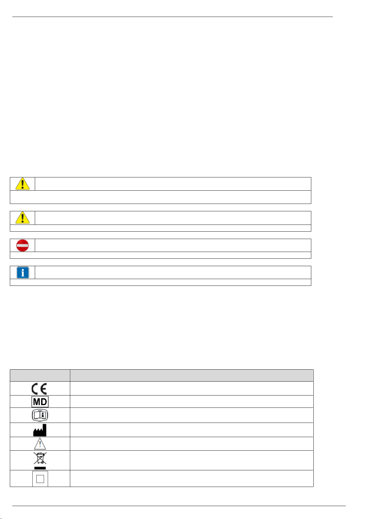
1.1 SYMBOLS USED IN THIS MANUAL ..................................................................................................................................................................................................3
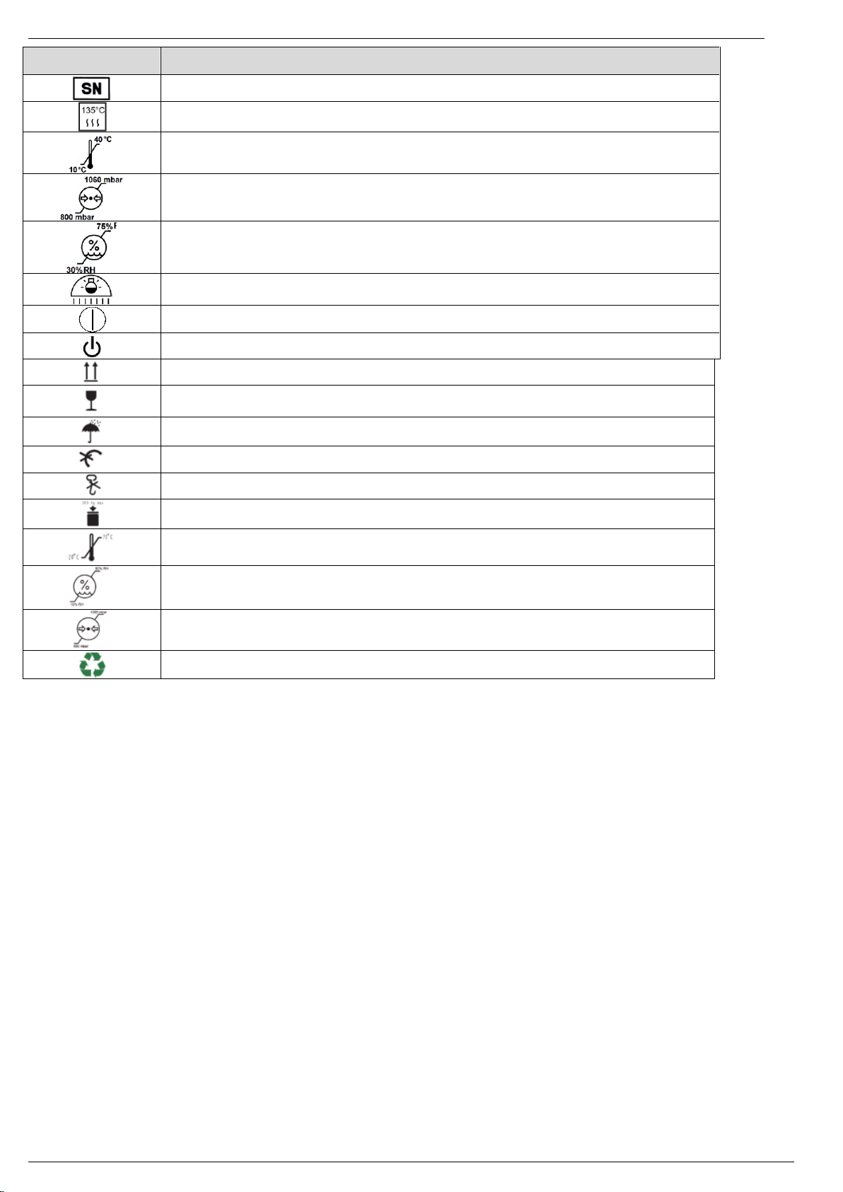
1.2 SYMBOLS USED IN THE LABELLING AND ON THE PACKAGING ..................................................................................................................................3
2INTENDED USE......................................................................................................................................................................................................................................................... 4
2.1 INTENDED USER ....................................................................................................................................................................................................................................... 4
2.1.1 Professional qualification:............................................................................................................................................................................................................ 4
2.1.2 Minimum skills................................................................................................................................................................................................................................ 4
2.1.3 Experience .........................................................................................................................................................................................................................................4
2.1.4 Possible user handicaps................................................................................................................................................................................................................ 4
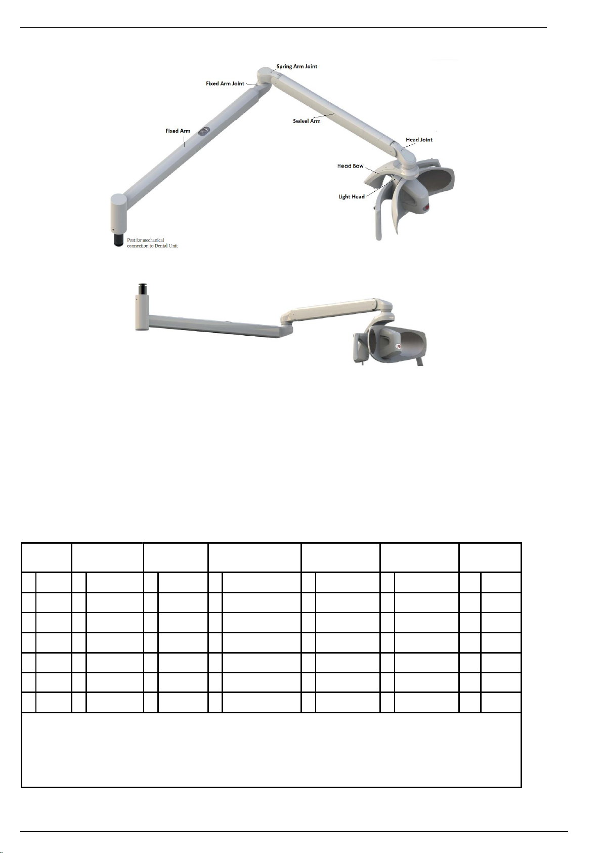
3DESCRIPTION OF THE PRODUCT................................................................................................................................................................................................................. 5
3.1 DESCRIPTION OF COMMON USER’S INTERFACE ................................................................................................................................................................ 6
4INSTRUCTION FOR USE..................................................................................................................................................................................................................................... 6
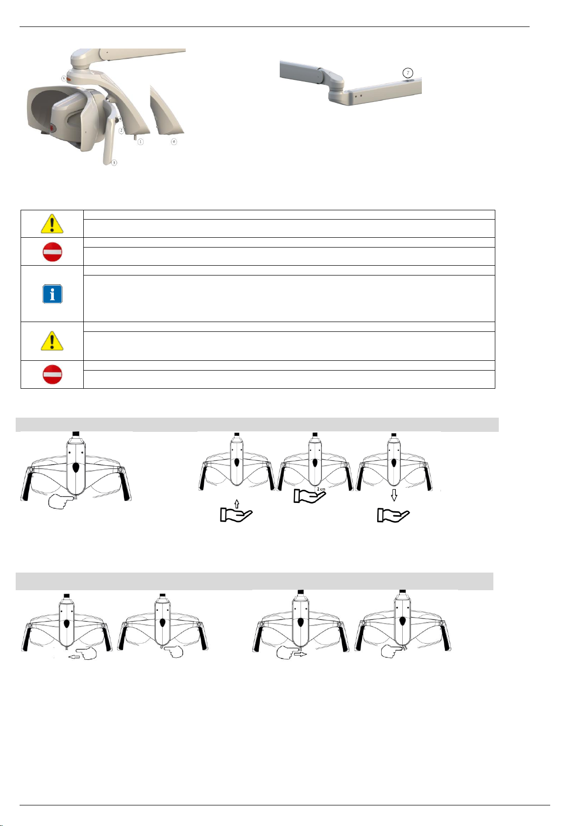
4.1 SWITCHING ON/ OFF............................................................................................................................................................................................................................. 6
4.2 ADJUSTING THE LIGHT INSTENSITY ........................................................................................................................................................................................... 6
4.3 CHANGING COLOR TEMPERATURE ON TUNABLE WHITE VERSION .....................................................................................................................7
4.4 COMPOSAVE SETTING ON TUNABLE WHITE VERSION................................................................................................................................................... 8
4.5 MINIMUM INTENSITY SETTING ON SOLAR VERSION ...................................................................................................................................................... 8
4.6 AUTO-ON SETTING ................................................................................................................................................................................................................................. 8
4.7 SWITCHING ON/ OFF THEIA............................................................................................................................................................................................................. 8
4.8 REMOTE CONTROL................................................................................................................................................................................................................................. 8
4.9 SYNCRO MODE WITH FARO ROOM LIGHT ............................................................................................................................................................................. 9
5PREVENTIVE MAINTENANCE AND ROUTINE CHECKS ................................................................................................................................................................10
6CLEANING AND DISINFECTION................................................................................................................................................................................................................... 11
6.1 CLEANING OF THE REFLECTING PARABOLAS ..................................................................................................................................................................... 11
6.2 CLEANING AND DISINFECTION OF THE HEAD .................................................................................................................................................................... 11
6.3 CLEANING AND DISINFECTION OF ARMS............................................................................................................................................................................... 11
7STERILIZATION OF THE HANDLES ............................................................................................................................................................................................................ 11
7.1 REMOVAL OF THE HANDLES ........................................................................................................................................................................................................... 11
7.2 DECONTAMINATION AND DISINFECTION.............................................................................................................................................................................. 11
7.3 STERILIZATION ........................................................................................................................................................................................................................................ 11
8TROUBLESHOOTING...........................................................................................................................................................................................................................................12
8.1 ERROR LIST.................................................................................................................................................................................................................................................12
9TECHCNICAL SPECIFICATIONS ...................................................................................................................................................................................................................12
9.1 STORAGE AND TRANSPORTATION: ENVIRONMENTAL CONDITIONS..................................................................................................................13
9.2 USE: ENVIRONMENTAL CONDITIONS........................................................................................................................................................................................13

EVA USER MANUAL - EN
Edition 1.0 April 2020 Pag. 3 di 14
Dear Customer,
FARO hopes you enjoy your work with the new high quality light. For safe work and to take full advantage of the performance of the product, read carefully
this manual before using the device.
In particular, follow all the warnings and the notes described into the Safety Recommendations included in the Packaging. .
Warranty Conditions:
FARO offers the final customer a 24 month warranty starting from the date of installation until a maximum of 30 months from the manufacturing date.
Repairs under warranty must be performed by FARO or its approved Service network.
Warranty is considered valid only when:
the user sent the Certificate of Warranty duly filled out at the following email: [email protected]
the user registered the warranty throughout the Faro website;
The warranty covers manufacturing and engineering defects; in case of valid claims, the warranty covers free parts replacement only. Manhour work is not
included in the warranty.
The warranty is not considered valid, at the sole discretion of FARO, if the fault is due to tampering, damage, unauthorized changes to the product, incorrect
use, improper maintenance and normal wear and tear.
This product have a Service Life of: 10 Years.
Any serious incident occurring in relation to the device should be reported to the Manufacturer and the competent authority of the Member State in which the
user and/or patient is established.
1SYMBOLS USED
1.1 SYMBOLS USED IN THIS MANUAL
WARNING
The paragraphs marked with this symbol contain instructions that must be carefully followed to avoid
damaging the device, harming the operator or the patient.
CAUTION
These instructions warns you that you must pay attention to avoid situations that could damage the device.
FORBIDDEN
This icon highlights what you should not do to avoid damaging the device.
NOTES
This icon supplies information that allows you to use the device more efficiently.
1.2 SYMBOLS USED IN THE LABELLING AND ON THE PACKAGING
The data plate is fixed:
• for the complete light or arms: on the rear arm
• for the head: under the heat sink cover
Serial Number description
For dental light YYLDNNNNNN
For head of dental light YYTENNNNNN
Where
YY: last two digit of the year of manufacturing
NNNNNN: progressive counter of the year
e.g.: 21LD000001 I the first product manufactured in 2021.
The following standardized symbols are also present:
Symbol
Description
Mark for Conformitè Europe
Medical Device according to Regulation (EU) 2017/745 of the European Parliament and of the Coucil of 5 April 2017 on
medical devices,
Read the instructions use. Supplied by Electronic means.
Manufacturer symbol according to Regulation (EU) 2017/745
The instructions for use include safety warnings
WEEE equipment according to the Directive 2012/19/EC. Dispose of
the product according to this directive.
Double insulation. Class 2 device against electrical risk

EVA USER MANUAL - EN
Edition 1.0 April 2020 Pag. 4 di 14
Symbol
Description
Serial Number
Can be sterilized with heat at 134°C
Use the device at a temperature between 10°C and 40°C
Use the device at pressure between 80 kPa and 106 kPa
Use the device at relative humidity between 30 RH and 75RH
Symbol to adjust light intensity
Symbol to switch on/off the light
Symbol to switch on/off the light on the rear arm (Alya with Theia Tech)
High
Fragile
Protect the packaging from rain and high humidity
Do not Roll
Do not use hooks
Maximum stackable weight
Storage and Trasportation temperatures
Storage and Trasportation Relative Humidity
Storage and Trasportation Atmospheric Pressure
Recyclable cardboard
2INTENDED USE
The device is used in dental office and is intended for illuminating the oral cavity and oral structures of patients in dentistry.
In the normal use, the device is positioned distance of 700mm from the operative area, the distance for which the lighting features were designed.
Patients can be of all ages with typical dental pathologies.
2.1 INTENDED USER
The intended users are Dentists (all specializations) or Dental Nurse, Hygienists and Assistants
2.1.1 Professional qualification:
Degree in Medicine with Dentistry Specialization
Degree in Dentistry
Degree in dental nursery
2.1.2 Minimum skills
Those planned for the professional qualification
Understanding of language: Those acquired for the professional qualification
2.1.3 Experience
Those outlined to conduct the profession
2.1.4 Possible user handicaps
For the use it is necessary at least one upper limb;
Visual faculty compatible with the profession;
The user with these characteristics does not require any special training

EVA USER MANUAL - EN
Edition 1.0 April 2020 Pag. 5 di 14
3DESCRIPTION OF THE PRODUCT
Picture 1 –Dental Light –Unit Mount
Picture 2 –Dental Light –Ceiling Mount
The device is available in two main product variants:
-EVA with light source at 5000 K with “Sunlight”Spectrum
-EVA with Tunable White light source (4000 K, 5000 K, 5700 K, Composave setting (2700 K)) selectable by the operator.
These main variants can be supplied with:
-Different Mounting:
-Different arm length combination
-Canbus Technology
-Remote cable for bring the command to the Dental Unit’s
-Auto-on setting;
-Theia Technology (secondary light source under fixed arm);
-Integrated Camera 2K or 4K;
-RF for the connection with FARO’s room lights (Siderèa)
All variants can be ordered by dedicated product codes as reported in the table below:
Mounting
1-2 DIGIT
Swivel Arm
3°DIGIT
Fixed Arm
4°DIGIT
Light Source /
Integrated Camera
5°DIGIT
Command /
radiofrequency (RF)
6°DIGIT
Cables
7° DIGIT
Custom (1)
8°-9° DIGIT
5
U
0
Only Head
No arms
0
Only Head
No arms
0
Tunable White
0
Joystick
0
Stnadard
00
Std faro
5
C
1
550 mm
1
600 mm
1
Sunlight 5000K
1
Joystick RF
1
Remote Control
Bus Cable
JJ
(4)
5
T
2
855 mm
2
600 mm
Theia
2
Tunable White
Integrated Camera
2
Sensor
3
820 mm
3
Sunlight 5000K
Integrated Camera
3
Sensor RF
4
820 mm
Theia
4
cNus
Tunable (2) (3)
5
960 mm
5
cNus
Sunlight 5000K (2) (3)
6
960 mm
Theia
(1) Customized codes include only aesthetic customization having no impact on Safety and EMC requirements
(2) cNus mark for Noth Amercia cannot be coupled with the following variant codes:
Digit 1-2: 5T
Digit 3: 0
Digit 5: 2 –3
(3) Ceiling Mounting Versions with cNus Mark are considered Fixed Applications and must be connected to Earth Protection. These devices are
Class 1 Insulation according to IEC 60601-1.
(4) Aesthetic branding customization not impacting on Safety and Performance requirements

EVA USER MANUAL - EN
Edition 1.0 April 2020 Pag. 6 di 14
3.1 DESCRIPTION OF COMMON USER’S INTERFACE
1Joystick
2Button for pairing and Tk change
3Sterilizable Handle
4Knob of the handle
5Indicator Strip
6Sensor (alternative to Joystick)
7Button for Theia Tech
4INSTRUCTION FOR USE
The device must be cleaned before use (see Device Cleaning paragraph).
Caution
Do not use the device in flammable or explosive environments
Simultaneous use of the light with electro-surgical devices can cause malfunctioning (flickering, no command, etc)
Warning
The Joystick must be handled with care to avoid breakages.
Never move the light using the switch to grip.
Note
At the switching on the device makes a self diagnosis, and the Indicator strip starts blinking with different colours: blue, green
and red.
The following parameters are memorized by the lamp and made available at every switching on:
Last light intensity setting
light colour temperature Setting (for Tunable White variant)
Warning
Do not use the device if parts or enclosures are damaged or plays or gaps appear between:
Head Bow / Head Joint
Fixed Arm Joint / Swivel Arm Joint
Warning
The joystick must be handled with care to avoid breakages.
Never move the light using the joystick.
4.1 SWITCHING ON/ OFF
Joystick
Sensor
Push right or left and release
Acoustic signal: 1 beep
Bring the hand towards the sensor up to 2 cm and move the hand down
Acoustic signal: 1 beep
4.2 ADJUSTING THE LIGHT INSTENSITY
Joystick Increase Light Intensity
Joystick Decrease light intensity
Push left and keep pushed until desired intensity is reached. Then
release
Acoustic signal: 1 beep at command
Maximum intensity reached: continuous beep
Push right and keep pushed until desired intensity is reached, then
release.
Acoustic signal: 1 beep at command
Minimum intensity reached: continuous beep

EVA USER MANUAL - EN
Edition 1.0 April 2020 Pag. 7 di 14
Sensor - Increase and decrease light intensity
Bring the hand towards the sensor up to 2 cm and keep this
distance until the desired light intensity is reached
Acoustic signal: 1 beep at command
Maximum intensity reached: 2 beeps
Minimum intensity reached: 1 beep
in sensor version the light intensity changes
continuously decreasing until minimum and
increasing until maximum
Note
when changing the light intensity the indicator light changes according to the illuminance level, according to the images below:
Light Intensity:
Minimum
Light Intensity:
Medium Minimum
Light Intensity:
Medium Maximum
Light Intensity:
Maximum
4.3 CHANGING COLOR TEMPERATURE ON TUNABLE WHITE VERSION
Joystick and Sensor
Every time a double click is performed, the Tk of the light changes.
Repeat the procedure until the desired colour temperature is shown on the indicator light.
2 beeps will inform the user that Tk is changing.
Sunlight Version
Tunable White Version
TK 5000 K
Green Luminous Indicator Strip
TK 4000 K
Yellow Luminous Indicator Strip
TK 5000 K
White Luminous Indicator Strip
TK 5700 K
Blue Luminous Indicator Strip

EVA USER MANUAL - EN
Edition 1.0 April 2020 Pag. 8 di 14
4.4 COMPOSAVE SETTING ON TUNABLE WHITE VERSION
Composave setting allow the user to work with restorative material avoiding their polymerization.
Select the composave setting as described below:
Joystick version option 1
Joystick version option 2
Visual information
At the command selection of
compo save a wigwag beep will be
heard. Indicator strip changes in
orange.
exit from the compo-save setting
with a single click from Compo-
save Setting
Sensor version
Visual information
4.5 MINIMUM INTENSITY SETTING ON SOLAR VERSION
Joystick version
Sensor version
Visual Information
4.6 AUTO-ON SETTING
When the on-mode in set in on position the lamps turn on automatically (without a specific command from the user) when there is power supply.
4.7 SWITCHING ON/ OFF THEIA
The light on the fixed arm (secondary light) can be switched on/off and
adjusted in synchro-mode with the operatory light and its command.
The secondary light can be manually operated using the button (7) on the
fixed arm.
If the secondary light is switched on after the operatory light, it will be
automatically synchronized.
If the secondary light is switched on with the operatory light switched off, it
will be automatically settled at the maximum intensity.
The light on the fixed arm is adjusted in synchro mode with head,
it cannot be adjusted independently.
4.8 REMOTE CONTROL
Make reference to the Dental Unit’s instruction for use the Dental Light from the Dental Unit’s control panel

EVA USER MANUAL - EN
Edition 1.0 April 2020 Pag. 9 di 14
4.9 SYNCRO MODE WITH FARO ROOM LIGHT
When present, the device can be connected by Radio Frequency (RF) connection to the Faro Room Light to
create a synchronized lighting system.
The procedure to create this connection is called “pairing”.
If more than one Room Lights are installed in the cabinet, take care that the other Room Lights are turned
off or are turned on for more than 60 seconds.
To activate the “Pairing”, proceed as follows:
1. Switch on the Faro Room Light. The Room Light will start Searching an input from the dental light for 60
seconds.
2. Within the 60 seconds, press the “Pairing” button on the dental lamp between 4 and 6 seconds. But not
for more than 6 seconds ( otherwise the procedure will be cancelled).
The Room Light activates the blue LED on the aluminium body.
If the blue LED does not switches on, it is possible another attempt (within the 60 seconds by
the firsts). If 60 seconds past from the switching on of the Room Light, it is necessary to repeat
the procedure from point 1.
3. After the blue LED switches on the room light, there are 60 seconds to confirm the “Pairing” by pressing
the programming button placed on the remote control of the Room Light. At this point, the blue LED of the
Room Light blinks at double frequency and then switches off. If the button on the remote controls is not
pressed within 60 seconds, the blue LED switch off and the procedure must be repeated from point 1.
After the “Pairing”, synchronization between the 2 lamps (dental light and room light) is enabled.
To DE-ACTIVATE THE SYNCHRONIZATION FUNCTION, proceed as follows:
Press the Synchro button from 2 to 4 second, then release it.
On release, a sound signal (Beep) will be heard and the blue LED on the Room Light lamp will go out to
indicate that synchronization has been disabled.
When the Faro Room Light is synchronized with the Dental Light the blue LED on the room light is lighted in steady mode. If the LED is off, the
synchronization is not active.
The remote control is always enabled, so it is possible to change the illumination value in manual mode.
If the Dental Light is turned off, the room light will remain switched.

EVA USER MANUAL - EN
Edition 1.0 April 2020 Pag. 10 di 14
5PREVENTIVE MAINTENANCE AND ROUTINE CHECKS
Only Service Engineer are allowed to perform corrective Maintenance and replacement of any part of the device, according to Manufacturer’s Service
Manual.
Checks
Frequency
Procedure
Responsible
No plays or space gaps between the
junction points (points 1, 2, 3, 4)
Yearly
Service
Engineer
Screws of connection points must
be tightened and integer:
screws 5
Screw 6.
Yearly
Service
Engineer
The nuts of connection points
under carter 1, 2 must be well
secured and safety screws intact.
The screws under carter 3 must be
well secured.
Yearly
Carter 3 Carter 2 Carter 1
Service
Engineer
Check the absence
of any oxidation into joints, arms or
plastic parts.
Yearly
Visual inspection
Service
Engineer
Check the main plate can be read
Yearly
//
Service
Engineer
Check of damages on enclosure and
plastic joints integrity.
Yearly
Service
Engineer
Electrical Safety according EN
62353
1. Dielectric strength
2. Current Leakage
Every two
years
Use the parameters defined into IEC 60601-1
Service
Engineer
Light checks
Every two
years
With a spectroradiometer check the values for:
Max Luminance: >35000 lux
CRI > 85
Radial power on blue light: <100 W/m2
Service
Engineer

EVA USER MANUAL - EN
Edition 1.0 April 2020 Pag. 11 di 14
6CLEANING AND DISINFECTION
Warning against danger of wear and corrosion and falling suspended mass
For all metal or plastic parts it is strictly forbidden to use substances that are
-abrasive,
-corrosive,
-acids,
-substances containing chlorine or chloride ions, phosphorous or phosphorous ions,
-detergents with Trilene base, petrol, white spirit, chlorine or similar.
Do not use detergents-disinfectants containing the following substances to clean plastic parts:
-Ammonium Hydroxide
-Sodium Hydroxide
-Hydrogen peroxide
-Ammonium Chloride
-Methylene chloride
-Methyl alcohol
-Acids and corrosive substances of all kinds.
It is forbidden to directly spray any chemical substance on the device.
It is forbidden the use of wet wipes without rinsing.
Faro tested and suggests the use of the following disinfectants, for plastic parts and metal parts:
-Durr FD366 Sensitive
-Faro Perflex Advanced
-Water-alcohol based disinfectants with 70% isopropyl alcohol or ethanol are suitable.
6.1 CLEANING OF THE REFLECTING PARABOLAS
Cleaning must be carried out using a soft cloth in cotton or absorbent cotton with ethyl alcohol.
Water-alcohol based disinfectants are suitable with 70% isopropyl alcohol or ethanol.
Caution - potential damage or wear on the parabolas
Never spray detergent directly on the parabolas.
Cleaning operations on the parabolas must be carried out wearing gloves, to avoid leaving fingerprints on the surfaces.
Never use detergents containing surfactants or water-repellents that depositing can leave streaks. Slight streaking will not
prejudice the quality of the light.
Products differing from those suggested could damage the parabolas.
If in doubt, contact FARO customer care.
6.2 CLEANING AND DISINFECTION OF THE HEAD
Cleaning must be carried out using a soft cloth in cotton wetted with disinfectant solution.
Always squeeze the cloth to remove all the liquid in excess.
6.3 CLEANING AND DISINFECTION OF ARMS
Always use a cloth soaked in disinfectant approved to disinfect the surfaces and pass it over.
Always squeeze the cloth to remove all the liquid in excess.
7STERILIZATION OF THE HANDLES
Warning - danger of cross contamination
The handles are not supplied sterile, they must therefore be sterilised before
use. The handles must be sterilised before each patient.
7.1 REMOVAL OF THE HANDLES
To remove the handle, unscrew knob “A” and remove it from the support.
7.2 DECONTAMINATION AND DISINFECTION
Before sterilising the handles, they must be decontaminated and disinfected.
To disinfect, Faro has tested the following products for disinfection:
Faro Perflex Advance
Durr FD366 Sensitive
WARNING - danger of plastic breaking
The handles cannot be disinfected by thermo-disinfection.
7.3 STERILIZATION
The handles must be packaged in compliance with EN 868-5.
The handles can be sterilised with standard cycles 121°/134° C up to two hundred (200) cycles or however up to loss of the
mechanical performance.
The parameters of the sterilisation cycle are as follows:
Cycle EN 13060
Temperature
Pressure
Holding Time Minimum
B
121°C
207 kPa
15 min
B
134°C
308 kPa
3 min

EVA USER MANUAL - EN
Edition 1.0 April 2020 Pag. 12 di 14
8TROUBLESHOOTING
8.1 ERROR LIST
Error
Description
Indicator Strip
Acoustic indication
E1
Open Led channel 1
First sector blinking.
Colour set-up: RED
3 short beeps repeated 3 times
E2
OPL Open Led channel 2
First and second sectors blinking
Colour set-up: RED
E3
High temperature on the Led group
No
No
E4
Low or High input voltage
All sectors blinking together.
Colour set-up: RED
5 lounge beeps
E5
Over Temperature Protection active
First sector blinking.
Colour set-up: PURPLE
3 lounge beeps
E6
High temperature on the board
All sectors blinking sequentially.
Colour set-up: PURPLE
3 lounge beeps
9TECHCNICAL SPECIFICATIONS
Dental Light
Dental Light Head
Dental Light with
Theia Tech
Power Supply
24 V ac ±10% 50/ 60Hz;
32 V dc ±10%;
24V ac ±10% -50/60 Hz;
32 V dc ±10%;
Max Power :
24 V ac 26 VA
32 V dc 14 VA
24 V ac: 40 VA
32 V dc: 28 VA
Recommended fuses for installation (not supplied in charge to installation)
24 V ac T1.6AL 250V
32 V dc T1.25AL 250V
24 V ac: T2AL 250V
32 V dc: T1.25AL250V
Protection against electrical hazard
Class II
Class I for Ceiling Mounting for Canada US Certification
NB: final classification of the Protection Class of the Medical System
is demanded to the Service Engineer in charge of installation or to
the manufacturer
Classification against IEC 62471
Class 1 - Labelling Exempt
Max illuminance (*)
> 45.000 lux
Color Rendering Index (*)
> 95
Correlated Colour Temperature CCT (*)
Sunlight Version: 5.000 K
Tunable White Versions: 4000 K –5000 K –5700 K
Composave setting : 2700 K
Spot Dimension (*)
180 mm x 110 mm
Max Hard Shadow ISO 9680 (*)
10 mm x 5 mm
Nature of the radiation
Non ionizing Radiation
Type of radiation
Visible lights
Typical illuminance Pattern ISO 9680
Overall Movements
Head Rotations

EVA USER MANUAL - EN
Edition 1.0 April 2020 Pag. 13 di 14
(*) Typical optical values subjected to tolerances
Measurement performed at 700 mm distance. Contact Faro for the correct procedure for the measurement.
9.1 STORAGE AND TRANSPORTATION: ENVIRONMENTAL CONDITIONS
The device in the original packaging can be transported and stored for a maximum period of 15 weeks if the following environmental conditions are met:
-Environmental temperature from -20°C to + 70°C
-Relative humidity from 10% to 90%
-Atmospheric pressure from 50 kPa to 106 kPa
9.2 USE: ENVIRONMENTAL CONDITIONS
-The device must be used in the following environmental conditions:
-Temperature from 10° to 40°C
-Max altitude: 2000 m
-Relative humidity from 30% to 75%

EVA USER MANUAL - EN
Edition 1.0 April 2020 Pag. 14 di 14
Table of contents
Other Faro Lighting Equipment manuals