Fast TS21 User manual

INSTRUCTION
MANUAL
TS21
2 Heating and 1 Cooling

Flexible applications - Universal and easy to install in
residential or commercial environments.
Advanced features - Precision electronics provide premium
comfort and temperature accuracy +/- 1 degree F.
Simple to use - Set and Forget with an easy to use menus
so straightforward no instruction manual is needed. 7 day
Programmable with 4 events each day including fan.
Technology that works for you - Easy to use, easy to see
touchscreen
ALL BACKED WITH A 2 YEAR WARRANTY
OVER THE COUNTER.
WELCOME TO

WIRING TABLE
CONFIGURATION Y1 Y2 W2 OB/W R/C R/H G
Cooling Only
Air Conditioner Furn. Off AC x x x
2 Air Conditioner Furn. Off AC1 AC2 x x x
Heating Only
No Compressor Electrical Furn. El.Furn El.Furn2* x x x
No Compressor Emg. El. Furn. Emg. El. Furn. El.Furn El.Furn2* x x x
No Compressor Gas Gas Gas2* x x x
No Compressor Oil Oil Oil2* x x x
No Compressor 2 Stage Gas Gas1 Gas2 x x x
* if there is another furnace, then connect it to OB/W relay.
1 Stage Cooling, 1 Stage Heating
Heat Pump Furn. Off HP OB x x x
Air Conditioner Electrical Furn. AC El.Furn x x x
Air Conditioner Emg. El. Furn. AC Emg. El. Furn. El.Furn x x x
Air Conditioner Gas AC Gas x x x
Air Conditioner Oil AC Oil x x x
MOUNTING THE THERMOSTAT TO THE WALL
1. Make sure to turn off the power supply located at the electrical service panel. All heating and
cooling units should be OFF.
2. Remove the cover plate by pulling up the cover from the left or right side only.
3. Align the thermostat unit to the wall.
4. Mark the two locations for drilling the 3/16” holes required for the plastic screw anchors.
5. Remove the thermostat and drill the two 3/16” holes in these locations.
6. Insert the plastic gyproc screw anchors and tighten them securely.
7. Make the appropriate wire connections based on the specifications of the household HVAC unit(s).
Please refer to Wiring Diagram to determine the appropriate wire connections.
8. Securely mount the thermostat unit to the wall with the two supplied screws.
9. Fit the cover plate back by clipping one side first (left or right) and than push down on the
opposite side.
10. Turn on the electricity at the electrical service panel.
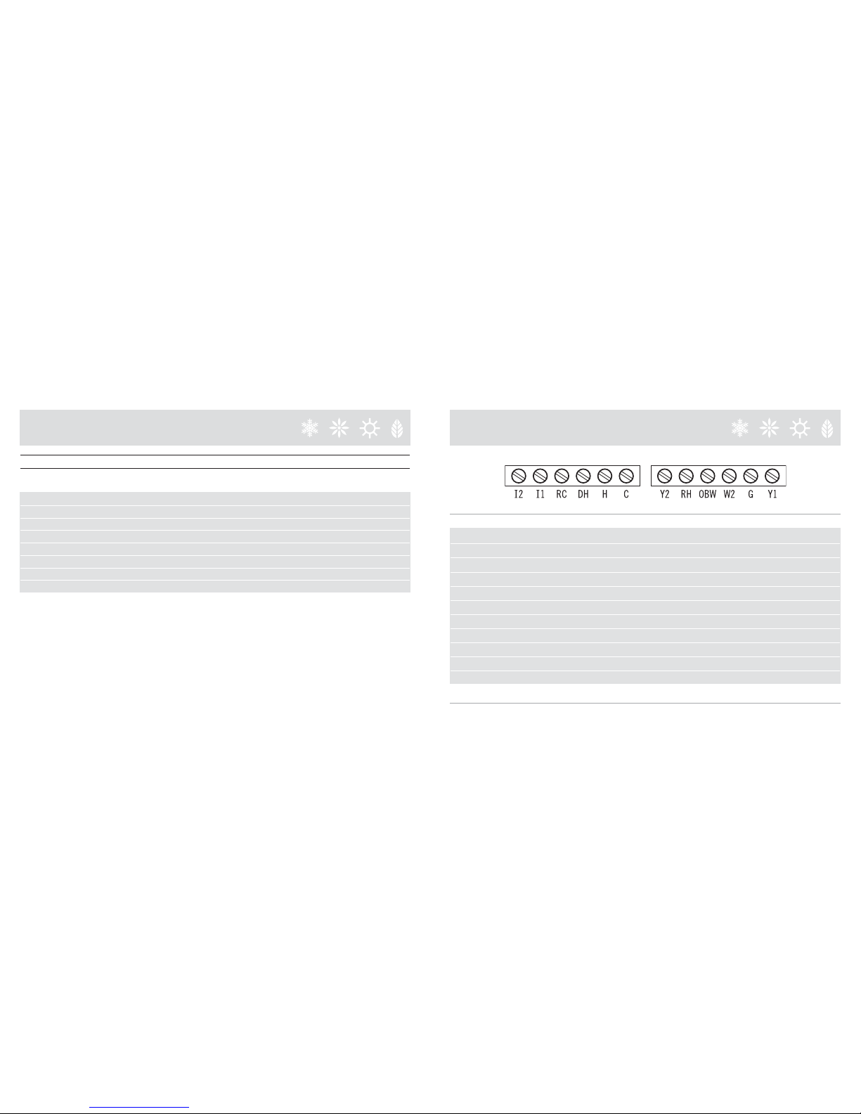
WIRING LEGEND
TERMINAL EQUIPMENT STANDARD COLOR
Y1 First Heat Pump & AC Yellow
G Fan Green
W2 First Stage Furnace White
OBW Reverse Valve - Second Stage Furnace Orange
RH 24v Red
Y2 Second Heat Pump & AC Unknown
C Common Blue
H Humidity Control Unknown
DH Dehumidity Control, Variable Fan Control Unknown
RC 24v Unknown
11 & 12 Not Used
NOTE: The above colors are standard in HVAC industry. The wiring should be confirmed before installation
WIRING TABLE
CONFIGURATION Y1 Y2 W2 OB/W R/C R/H G
1 Stage Cooling, 2 Stage Heating
Air Conditioner 2 Stage Gas AC Gas1 Gas2 x x x
Air Conditioner Electrical Furn. AC El.Furn1 El.Furn2 x x x
Air Conditioner Emg. El. Furn. AC Emg. El. Furn. El.Furn1 El.Furn2 x x x
Air Conditioner Gas AC Gas1 Gas2 x x x
Air Conditioner Oil AC Oil1 Oil2 x x x
Heat Pump Electrical Furn. HP El.Furn OB x x x
Heat Pump Gas HP Gas OB x x x
Heat Pump Oil HP Oil OB x x x

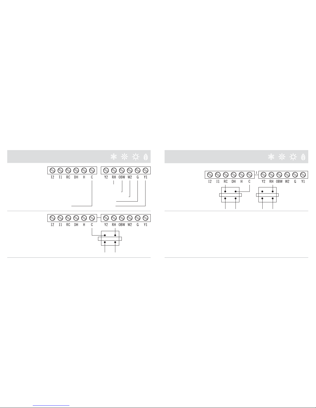
AC & ONE HEAT
AC & TWO HEAT
24V (RED)
Heat (WHT)
Fan (GRN)
AC (YLW)
COMMON (BLUE)
24V (RED)
Heat2
Heat1 (WHT)
Fan (GRN)
AC (YLW)
COMMON (BLUE)
WIRING DIAGRAM
ONE AC
TWO AC
24V (RED)
Fan (GRN)
AC (YLW)
COMMON (BLUE)
AC2 (YLW)
24V (RED)
Fan (GRN)
AC1 (YLW)
COMMON (BLUE)
WIRING DIAGRAM

ONE HEAT PUMP
& TWO HEAT
TWO HEAT PUMP
WIRING DIAGRAM
Heat 2
24V (RED)
Reverse Valves (ORG)
Heat 1 (WHT)
Fan (GRN)
HP (YLW)
COMMON (BLUE)
HP 2
24V (RED)
Reverse Valves (ORG)
Fan (GRN)
HP 1 (YLW)
COMMON (BLUE)
ONE HEAT PUMP
ONE HEAT PUMP
& ONE HEAT
WIRING DIAGRAM
24V (RED)
Reverse Valves (ORG)
Fan (GRN)
HP (YLW)
COMMON (BLUE)
24V (RED)
Reverse Valves (ORG)
Heat (WHT)
Fan (GRN)
HP (YLW)
COMMON (BLUE)
TWO
TRANSFORMERS
HEAT
TRAN
CUT
COOL
TRAN
WIRING DIAGRAM
AC & TWO STAGE
FURNACE
ONE
TRANSFORMER
24V (RED)
2nd Stage Heat
1st Stage Heat (WHT)
Fan (GRN)
AC (YLW)
COMMON (BLUE)
HEAT
TRAN
WIRING DIAGRAM

5
6
7
1
9
11
2
3
4
8
10
7Security On Indicator; to change, go to 31.
8Heating set point; to change, go to 13.
9Cooling set point; to change, go to 13.
10 Date (Month/Day/Year); to change, go to 20.
11 Time; to change, go to 20.
1 Room Temperature; to change ºF/ ºC, go to 30.
2 Thermostat Control Mode; to change, go to 15.
3 Temperature Control Mode; to change, go to 14.
4 Fan Operation Mode; to change, go to 16.
5 Fan Operation Indicator; to change, go to 16.
6Vacation Mode Indicator; to change, go to 24.
TO RETURN TO THE HOME PAGE,
SIMPLY TOUCH ICON
AT ANY TIME!
12 Current Room Temperature.
13 Heat and Cool temperature set points; to change, raise
or lower set point as desired. In “Auto” mode touch
Heat/Cool button (Heat or Cool will flash once
selected), then raise or lower set points as desired.
14 Temperature Control Mode; select between Heat / Cool
/ Auto / Emergency Heat.
15 Thermostat Operation Mode: Select between “Run
Program” mode (for details, see 21 ) or “Hold
Temperature” mode.
*
TO ACCESS THE CONTROL PAGE,
SIMPLY TOUCH THE HOME PAGE
SCREEN… ANYWHERE!
18
12
17
15
14
16
19
*13
16 Fan Operation Mode: select between Fan Automatic-
where the fan will turn on only when there is a demand
for heating or cooling. Fan Continuously On – the fan
runs continuously/ Fan Intermittent.
In the fan inter-
mittent mode the fan will run for 10 minutes per _
hour which is a convenient way to filter the air and
conserve energy.
17 Displays Installer Message; to enter a message,
go to 33.
18 Return to Home Page.
19 Access the Menu Page.
HOME PAGE CONTROL PAGE

27
24
25
26
20
21
22
23
27
24
25
26
20
21
22
23
20 Set Date and Time.
21 Program temperature and fan events by:
• Select the Day of the week.
• Select the Event number
• Select the Start time of the Event
• Select the desired temperature setpoint
• Select the next Event number and repeat steps
3 and 4.
• Once you have set all the events for one day you
may copy the same settings to other days of the
week. First ensure that your program settings are
correct. Then select the next day of the week that
you would like to have the same program setting.
• The thermostat will then prompt you to copy the
settings. To activate the program select run
program from the control page.
22 Displays system energy consumption and cost: to
enter system consumption parameters, go to 29;
otherwise, displays fan and compressor runtime.
• Select the End Date
• Adjust the Heat or Cool temperature setpoint.
• The Vacation Mode begins at 10 PM on the day
of your departure and ends at Midnight on the
day of your arrival.
• When the Vacation Mode is active the suitcase
icon will appear on the main page. When you
return from vacation, you will see a message
Vacation Mode Ended displayed on the screen,
simply touch the screen to acknowledge the
message.
23 This function allows you to wipe and clean the screen
with a dampened cloth with out accidentally
changing any of the settings; it place the thermostat
screen in a sleep mode for 15 seconds.
24 Vacation settings allows you to set the temperature
to a fixed setpoint during the time you are on
vacation. Please note that either Heat or Cool must
be selected from the control page before entering the
Vacation Settings page. To active the feature select
Vacation Mode ON-
• Select the Start Date
MENU PAGE
TO ACCESS THE MENU PAGE,
SIMPLY TOUCH
FROM THE CONTROL PAGE.
MENU PAGE
TO ACCESS THE MENU PAGE,
SIMPLY TOUCH
FROM THE CONTROL PAGE.

27
24
25
26
20
21
22
23
•Contrast: set screen contrast from 1-11.
27 To access “Advanced Settings”, hold finger 5
seconds on icon. A warning will appear:
Caution: Incorrect configuration
can damage your system, continue?
YES NO
25 Displays filter usage in days and resets filter timer.
26 Set Screen Options:
•Daylight Time (ON/OFF): activate only if you are
located in a “Daylight Savings Time” zone.
•Reverse: Select between dark background (ON)
or light background (OFF)
•Night Reverse: Select between ON: Automatically
reverses screen background for comfortable
viewing at night (from 9PM to 6AM) OFF: screen
background determined by “Reverse” function
setting.
• You will be prompted to: (first time user) Enter
the default PIN
• Enter your new PIN Re-enter your new PIN
• There are two modes of password protection: Full
Lock and Partial Lock
• The full lock Function does not allow any changes
unless the user enters the PIN
• Partial Lock allows you to change only the
temperature setpoint without entering a PIN.
32 Enter “Installer Message” (up to 42 characters) to
appear at programmable intervals, see 17.
28 Turn “Filter Monitor” ON or OFF; if ON enter the
filter replacement interval.
29 Enter HVAC system consumption parameters
rounded off to kW; see 26 (Typically: Fan 1kW; Heat
Pump 1kW/ton; Furnace 5-30 kW, 7-9¢/kW)
30 Change thermostat temperature display units (ºF or ºC).
31 Turn “Security” ON or OFF (Default Security PIN =
1111) and select the security level: The security
settings allow you to protect your thermostat
thermostat from unauthorized use.
• Turn Security On or Off ( Default pin 1111)
31 32
28 29 30
MENU PAGE
TO ACCESS THE MENU PAGE,
SIMPLY TOUCH
FROM THE CONTROL PAGE.
ADVANCED SETTINGS PAGE 1

37 Set temperature difference between temperature set
point and actual temperature reading before 1st stage
heating or cooling is initiated.
38 Set temperature difference between 1st stage
initiation (37) and 2nd stage heating or cooling
initiation.
37
38
39
40
35 Set maximum compressor cycles per hour.
36 Set Minimum difference between auto mode heat and
cool temperature set points. See 14.
39 Set temperature difference between 2nd stage
initiation (38) and 3rd stage heating or cooling
initiation.
NOTE: Number of stages depends on your system;
see 33 & 34.
40 Reverses the Heat Pump OB Valve contact;
(manufacturer dependant)
34 36
33 35
33 Select system heating and/or cooling equipment:
Heat Pump, 2-stage Heat Pump, Air Conditioning, No
Compressor – see Wiring Diagram.
34 Select the system Furnace Type:
Furnace Off (No Furnace), Electric Furnace, Emergency
Electrical Furnace (additional electric furnace which
will come on in emergency mode in conjunction with
electric furnace), Gas Furnace, Oil Furnace, and 2-stage
Gas Furnace; see Wiring Diagram.
ADVANCED SETTINGS PAGE 2 ADVANCED SETTINGS PAGE 3
PLEASE NOTE THAT INADVERTENTLY
MODIFYING COMPRESSOR AND
FURNACE SETTINGS, MAY SERIOUSLY
DEGRADE SYSTEM PERFORMANCE.

41 Specify X minutes for which stage 1 will function until
stage 2 is activated to help raise (or cool) temperature
(if the temperature set point is not reached). This
function avoids excess compressor wear in the case
where the necessary temperature set point is not met
(see 37, 38 & 39). Set to “00” to disable.
41
42 HP “ON” when Furnace On: Heat Pump and
Furnace can operate together when 2nd stage
furnace is required.
HP “OFF” when Furnace On: turns off the Heat Pump
when the furnace is On (required on some gas or oil
furnaces).
42
ADVANCED SETTINGS PAGE 4 ADVANCED SETTINGS PAGE 5

Touch screen buttons do not function properly.
Remove cover, press the reset button located in the
bottom left corner then accurately touch 3 target
centers on the screen when prompted.
PARTIAL LOCK and FULL LOCK do not function.
You must not touch the screen for 1 minute for the
thermostat to automatically lock.
I forgot my PIN and cannot unlock the thermostat.
Remove the cover plate, press the reset button located
in the bottom right corner, as soon as the message
“touch to reset password” appears touch the screen,
your PIN will be erased and the thermostat will
unlock.
Air conditioning turns on in HEAT mode and heating
turns on in COOL mode.
Reverse the OB valve (see “Advanced Settings” Page 3).
Thermostat appears normal until the screen becomes
blank when the compressor or heating system turn on.
You need to connect the “C” wire. 4 wire system will
not function unless the heat and compressor
contactors can supply enough current to power the
thermostat with only 4 wires, if you cannot hook up
the “C” wire another possible solution is to connect
two 250 ohm 10 watt resistors in the HVAC room, one
between Y and C, and the second one between W2
and C.
To enable “Simple Mode”, press the reset button
(take off the thermostat faceplate and press the reset
button located in the bottom right-hand corner). The
message “Touch for Simple Thermostat” will appear.
Touch the screen, and the thermostat becomes a sim-
plified non-programmable thermostat.
* Please note that when changing to Simple Mode,
you will not lose any of the settings you have
previously entered in the “Programmable Mode”.
* To revert back to the Programmable Thermostat,
simply press the reset button and touch the
screen when the message “Touch for Programmable
Thermostat” appears.
SIMPLE THERMOSTAT MODE
Simple Mode has the following basic features:
Temperature Control Modes:
Fan Operation Modes:
THERMOSTAT CAN ALSO FUNCTION
AS A NON-PROGRAMABLE THERMOSTAT
AFTER IT HAS BEEN CONFIGURED.
TROUBLESHOOTING

When using this thermostat with a gas furnace a
common wire (C) must be connected.
When working without a common wire:
Aconfirm in heat mode the cooling does not switch
on or Bconfirm in cooling mode the hear does not
switch on
If test Aor Bfail or the thermostat shuts down in either
heat or cool mode then it is necessary to connect a
common wire, (C), alternatively it may be possible to
solve this issue by simply connecting the 250 ohm 10
watt resistor between C and W (in the case of a cooling
problem – see B) or between C and Y1 (in the case of
a heating problem - see A) at the HVAC equipment.
When working without a common wire, A confirm that
when there is a call for heat, cooling does not also
activate, and when there is a call for cool, heating does
not also activate.
If using the configuration of Heat Pump and Furnace
with no Common Wire confirm that when Heat Pump
and Furnace are working together (both stages are
operating at the same time) that the display does not
go blank, if so you must use a Common Wire.
This thermostat is equipped to run with two separated
power transformers if required RC and RH. Terminals
RC and RH are internally connected together however
you should wish to use two transformers simply cut
with a blade the copper trace on the printed circuit
board located between the C and Y2 screw terminals.
IMPORTANT NOTICE LIMITED WARRANTY
Obtaining Warranty Service
Customer must contact and return product to a local Fast Parts
Division - International Comfort Products, LLC product dealer or
installer within the applicable warranty period to obtain warranty service.
Dated proof of original purchase will be required. Fast Parts Division -
International Comfort Products, LLC will not be responsible for
Customer’s memory data contained in, stored on, or integrated with
any products returned to Fast Parts Division - International Comfort
Products, LLC for repair, whether under warranty or not.
Warranty Exclusive
THE FORGOING WARRANTIES AND REMEDIES ARE EXCLUSIVE
AND IN LIEU OF ALL OTHER WARRANTIES, EXPRESS OR IMPLIED,
INCLUDING WARRANTIES OF MERCHANTABILITY, FITNESS FOR A
PARTICULAR PURPOSE, CORRESPONDENCE WITH DESCRIPTION,
AND NON-INFRINGEMENT, ALL OF WHICH ARE EXPRESSLY
DISCLAIMED BY FAST PARTS DIVISION - INTERNATIONAL
COMFORT PRODUCTS, LLC AND ITS SUPPLIERS.
Disclaimer
NEITHER FAST PARTS DIVISION - INTERNATIONAL COMFORT
PRODUCTS, LLC NOR ITS SUPPLIERS SHALL BE LIABLE FOR INCI-
DENTAL, CONSEQUENTIAL, INDIRECT, SPECIAL, OR PUNITIVE
DAMAGES OF ANY KIND, OR FINANCIAL LOSS ARISING OUT OF OR
IN CONNECTION WITH THE SALE OR USE OF THIS PRODUCT,
WHETHER BASED IN CONTRACT, TORT (INCLUDING NEGLIGENCE)
OR ANY OTHER THEORY, EVEN IF FAST PARTS DIVISION -
INTERNATIONAL COMFORT PRODUCTS, LLC HAS BEEN ADVISED
OF THE POSSIBILITY OF SUCH DAMAGES. FAST PARTS DIVISION -
INTERNATIONAL COMFORT PRODUCTS, LLC’S ENTIRE LIABILITY
SHALL BE LIMITED TO REPLACEMENT OR REPAIR OF THE PRODUCT.
Hardware
Fast Parts Division - International Comfort Products, LLC warrants the
original end user (“Customer”) that new FAST HVACR Parts thermostat
branded products will be free from defects in workmanship and materials,
under normal use, for two (2) years from the original purchase date.
Software
Fast Parts Division - International Comfort Products, LLC warrants to
Customer that the thermostat software will perform in substantial
conformance to its program specifications for a period of two (2) years
from the date of the original purchase.
Exclusions
This warranty excludes (1) physical damage to the surface of the product,
including cracks or scratches on the touch-screen or outside casing;
(2) damage caused by misuse, neglect, improper installation,
unauthorized attempts to open, repair, or modify the product, or any
other cause beyond the range of intended use; (3) damage caused
by accident, fire, power changes, other hazard, or Acts of God; or (4)
use of the product with any device if such device causes the problem.
Exclusive Remedies
Should a covered defect occur during the warranty period and
Customer notifies Fast Parts Division - International Comfort Products, LLC,
Customer’s sole and exclusive remedy will be, at Fast Parts Division -
International Comfort Products, LLC’s sole option and expense, to
repair or replace the product. Replacement products or parts may be
new or reconditioned or a comparable version of the defective item.
Fast Parts Division - International Comfort Products, LLC warrants any
replaced product or part for a period of ninety (90) days from shipment,
or through the end of the original warranty, whichever is longer.

FAST PARTS DIVISION - INTERNATIONAL COMFORT PRODUCTS, LLC
Technical Support: 1-866-908-6824
Physical Dimensions
Case: 5.75” x 4.75” x 1.25”
(145mm x 120mm x 30mm)
Display: 3.625” x 2.125”
(95mm x 55mm)
Electrical Rating
24 volt AC/DC
Class 2 maximum 4 amps
Temperature Accuracy +/-1°F degree
Power failure protection safeguards
clock and memory.
FCC Statement
THIS DEVICE COMPLIES WITH PART 15 OF THE
FCC RULES. OPERATION IS SUBJECT TO THE
FOLLOWING TWO CONDITIONS: (1) THIS DEVICE
MAY NOT CAUSE HARMFUL INTERFERENCE, AND
(2) THIS DEVICE MUST ACCEPT ANY INTERFERENCE
RECEIVED, INCLUDING INTERFERENCE THAT MAY
CAUSE UNDESIRED OPERATION.
US PATENT
6,786,421
OTHER PATENTS
PENDING
Table of contents
Other Fast Thermostat manuals


