Fedders Trion PORT-A-CART Operation manual

PORT-A-CART™
Portable Cartridge Air Cleaner
•INSTALLATION
•OPERATION
•SERVICE
For Industrial Applications
www.trioninc.com
Manual Part Number 157199-001· March 2004

2
Table of Contents
Specifications....................................................................................3
System Design..................................................................................3
Installation.........................................................................................3
Unpack and Inspect................................................................3
Installing Source Capture Arm ...............................................3
Positioning the Unit ................................................................4
Electrical Power Requirements.........................................................4
Operation ..........................................................................................4
Maintenance......................................................................................5
Cleaning Filter........................................................................5
Manual Cleaning ....................................................................5
Optional Pulse Cleaning.........................................................5
Recommended Operating Range...........................................5
The Cartridge Filter...........................................................................6
To Remove and Replace Filter...............................................6
Warranty............................................................................................6
Troubleshooting Guide......................................................................7
Figure 1 Wiring Diagram...................................................................8
Figure 2 Outline Diagram..................................................................9
Parts List.........................................................................................10
Figure 3 Parts List Diagram ............................................................11
Contact Information.........................................................................12
CAUTION:
READ INSTALLATION, OPERATION AND MAINTENANCE INSTRUCTIONS CARE-
FULLY FOR SAFE OPERATION
EXERCISE EXTREME CAUTION WHEN WORKING WITH ELECTRICITY

3
SPECIFICATIONS: PORT-A-CART™
Power Requirement: 120 volts, 60 Hz,
1 Phase, 17 amps,
1612 watts
Weight: 400 lbs. (180 kg)
Dimensions: 48.1”L x 29.5” W x 33.5” H
(1222 x 749 x 851 mm)
Filter Area: 190 Sq. Ft. (17.7 Sq. m)
Backflush Air Pressure: 80-120PSI(1/4” shop hose
or larger)
5.5-8.3 Pascals (6mm
shop hose or larger)
Arm: 6.5’ L, 8” diameter
externally supported
with 360 rotation
(2m x 200mm)
Pick-Up Velocity: 2000 FPM (10 MPS)
Duct Velocity: 2900 FPM (15 MPS)
Capture Zone: 12” to 18”
(300 to 450mm)
Filtered Air: 1000 CFM (1700 M3H)
SYSTEM DESIGN
SYSTEM DESIGN AND LAYOUT
WARNING!
The Port-A-Cart is NOT designed to collect
wet or oily particulate and should not be in-
stalled in applications collecting coolants,
grease, processing fluids or other types of
liquid aerosols. Contact the Trion sales de-
partment for special units for these type in-
stallations at 800-884-0002.
The Port-A-Cart Cartridge Air Cleaner is de-
signed to pick-up and collect dry solid particu-
late such as weld fumes and industrial dust.
Clean air is then discharged back into the
work space. The unit is equipped with cast-
ers, a source capture arm, a filtration compart-
ment, and a blower compartment. Simply roll
the unit to a level location near the source of
pollutants, adjust the arm, and place the cast-
ers in the locked position. Then connect the
electrical power and the unit is ready for op-
eration.
In operation, the pick-up arm delivers the con-
taminated air to the cartridge filter for collec-
tion. A Minihelic gauge monitors the pressure
across the cartridge filter and indicates when
cleaning should take place.
INSTALLATION
1. UNPACK AND INSPECT
Upon receipt, all shipping containers and their
contents should be examined for damage. Any
damage occurring in shipment must be imme-
diately reported to the carrier, an inspection
report completed and a claim filed with the
carrier at the receiving point.
The Port-A-Cart cabinet is shipped assem-
bled. Please check to ensure all components
are included:
• Painted steel cabinet with integral car-
tridge filter, casters, and power cord
• Minihelic gauge
• Drop-Out tray
• Source capture arm, hood, and mounting
hardware (shipped loose)
• Impregnated carbon filter (odor control)
2. INSTALLING SOURCE CAPTURE ARM
To simplify packaging and reduce the possibil-
ity of shipping damage, the source capture
arm is shipped separately. The necessary
mounting hardware is included with the arm.
Using washers and bolts provided, secure the
arm to the cabinet. The mounting holes are
pre-drilled. The tension is adjustable at each
arm elbow (five places). The hood tension
adjustment is located outside the hood.

4
3. POSITIONING THE UNIT
Roll the unit to a level floor space in the area in
which it is to be used. When the unit has been
properly positioned, lock the two swivel casters to
prevent movement during operation.
WARNING !
Combustible Materials Hazard
Can Cause Personal Injury, Death or
Equipment Damage
1. Due to potential fire hazards, do not mix
combustible materials with those that
would be a potential source of ignition.
Examples of combustible materials in-
clude but are not limited to: wood dust,
paper dust, lint from fabrics or buffing
wheels, grinding dust from painted sur-
faces and aluminum or magnesium
dusts. Examples of potential ignition
sources include but are not limited to:
grinding dust from ferrous metals or
sparks from any source.
2. This equipment should not be used for
the collection of any materials where
there is a risk of explosion. Pressure
relief or explosion vents should not be
applied to the equipment or any adjoin-
ing system.
3. Equipment location, installation and op-
eration should comply with all national
and local fire codes. When in doubt,
consult the proper authorities.
4. Workers and machine operators should
be instructed to keep any burning ob-
jects, such as cigarettes, safely away
from air inlets leading to the equipment.
5. All those involved with the use of this
equipment should comply with the
statements pertaining to worker safety
as noted in this manual.
WARNING !
Electric Shock Hazard
Can Cause Electrical or Equipment
Damage
Do not connect power before the installa-
tion is complete.
ELECTRICAL POWER REQUIREMENTS
The blower motor is 1 1/2 HP requiring a 120
volt, 60 Hz, 1 ph (17 amp) source of power.
The unit is supplied with a 10’ (4.7 m) power
cord.
OPERATION
Plug the power cord into a 120 volt, 60 hertz
outlet. Turn the power switch on.

5
MAINTENANCE
WARNING !
Sharp Edges Can Cause
Personal Injury
Wear protective gloves to prevent cuts from sharp
edges.
CLEANING FILTER
Quality equipment, such as your Trion Port-A-
Cart cartridge air cleaner, will require minimum
maintenance to keep it in good operating condi-
tion. The motor is a totally enclosed, fan-cooled
type with permanently lubricated bearings. No
maintenance is required other than to routinely
check for foreign debris in the arm hood, the
drop-out tray and the motor blower compart-
ments. Rubber gaskets should be checked twice
a year. Aging occurs primarily due to ozone pre-
sent in ambient air and eventually hardens the
rubber and causes cracking and loss of seal.
Contact Trion for replacement parts at
800-884-0002.
MANUAL CLEANING
The Minihelic gauge, located on the top surface
of the unit, monitors static pressure across the
cartridge filter. Note the gage reading on initial
start-up. As contaminants collect, the static pres-
sure will increase until the pick-up or capture
zone becomes ineffective. Filter cleaning is re-
quired at this point. Again, note the static pres-
sure gage reading. The clean filter and dirty filter
readings may be used for future reference in de-
termining the cleaning cycle.
To clean the filter cartridge, turn the unit blower
off and close the damper in the pick-up arm. Re-
move the filter access cover. Using a com-
pressed air gun or nozzle, backflush contami-
nants from the cartridge filter by directing the air
through the filter from the center of the cartridge.
The particulate blown from the cartridge is col-
lected in the dust tray located below the filter.
When the filter cleaning is complete, the dust tray
may need to be emptied.
Return the unit to operation by reattaching the
filter access cover and opening the damper in the
pick-up arm.
OPTIONAL PULSE CLEANING
A backflush pulse cleaning system is avail-
able. It consists of an air tank, a pulse valve
and a manual switch. The air tank is located
inside the blower compartment. The pulse
valve is located to direct a blast of air into the
center of the cartridge from the blower end.
The actuator switch is located on the top sur-
face of the unit.
To clean the cartridge, turn the unit off and
close the damper in the pick-up arm. Connect
a dry/ clean compressed air source (80-120
PSI, 5.5-8.3 Pascals) to the air inlet on the
top surface of the unit. The built-in air tank will
fill from the connected air supply. When the
tank is full, the air flow stops. Initiate back-
flushing by pushing the pulse switch. Repeat
the pulse cycle several times for best results.
When the filter cleaning is complete, the dust
tray may need to be emptied.
Return the unit to operation by reattaching the
filter access cover and opening the damper in
the pick-up arm.
RECOMMENDED OPERATING RANGE
* Resistance across the filter will increase
over time as contaminants become embedded
in the filter fibers. A reduction of 0.15” - 0.25”
after pulsing 5-10 times is common.
** When repeated pulsing and manual
cleaning does not reduce the gauge reading
below this range, airflow is typically insufficient
and the cartridge should be replaced.
Condition Gauge Reading Air Flow
New Filter,
No Pre-coat 1.8” -1.9” 1020-1000 CFM
New Filter,
After Pre-coat 2.1” - 2.2” 1000 CFM
Recommended
pulse range,
initial
2.4” - 2.5” 970-930 CFM
Recommended
pulse range,
final*
2.7” - 2.8” 910-885 CFM
Replace filter** 3.0” - 3.2” 800-700 CFM

6
THE CARTRIDGE FILTER
CAUTION: Before servicing any portion of
the air cleaner:
1. Disconnect the electrical power.
2. Shut off and bleed the compressed air
supply.
The backflushing process may lose effectiveness
on removing collected contaminants after ex-
tended use. (The filter life may be extended by
removing the filter from the cabinet and manually
directing compressed air into the center of the
filter to dislodge contaminants.)
TO REMOVE AND REPLACE FILTER
NOTE: Depending on the contaminant col-
lected, it may be advisable to wear a dust res-
pirator when handling dirty filters.
1. Open filter access cover.
2. Move cartridge filter slightly up and down to
break the rear gasket seal.
3. Rotate the cartridge 1/2 turn to permit any
loose contaminant falling from the top of the
elements.
4. Slide the cartridge filter out of the compart-
ment.
5. Clean any dust deposits from the rear gasket
seal area to assure a positive seal for the
replacement cartridges.
6. Remove excess contaminant from bottom of
compartment by brushing out or by vacuum-
ing.
7. Install new cartridge and replace access
cover.
WARNING !
Electric Shock Hazard
Can Cause Personal Injury or Death
LIMITED WARANTY
Trion warrants the equipment of its manufacture
to be free from defects in workmanship and ma-
terial for a period of 36 months after shipment.
This warranty is limited, however, to the repair or
replacement of defective equipment, which is
returned, freight prepaid, to manufacturer’s fac-
tory. This warranty does not cover any of the
replacement filters in the unit, i.e. cartridge filter,
HEPA (optional), Impregnated after filter.
This limited warranty does not apply to any part
or component that is damaged in transit or when
handling, has been subject to misuse, negli-
gence or accident, has not been installed, oper-
ated or serviced according to Seller's instruc-
tions, or has been operated beyond the factory
rated capacity or has been altered in any way.
Trion’s liability is limited to replacement of defec-
tive parts or components and does not include
any cost of labor (including, but not limited to,
labor required to remove and/or reinstall any de-
fective part) other than Trion factory labor.
Trion shall not be responsible for loss of use of
any product, loss of time, inconvenience, or dam-
age to other equipment or any other indirect or
consequential damage with respect to property
whether as a result of breach of warranty, neglect
or otherwise.
THE WARRANTIES AND LIABILITIES SET
FORTH ABOVE ARE IN LIEU OF ALL OTHER
WARRANTIES AND LIABILITIES, EXPRESSED
OR IMPLIED, IN LAW OR IN FACT, INCLUDING
ANY IMPLIED WARRANTIES OF MERCHANT-
ABILITY AND FITNESS FOR PARTICULAR
PURPOSE.
The foregoing shall constitute the total liability of
Seller in the case of defective performance of all
or any of the equipment or services provided to
Buyer. Buyer agrees to accept and hereby ac-
cepts the foregoing as the sole and exclusive
remedy for any breach or alleged breach of war-
ranty by seller.

7
TROUBLESHOOTING GUIDE
PROBLEM POSSIBLE CAUSE SOLUTION
Unit fails to start No power to the unit
Faulty motor
Faulty control switch
Check circuit
Replace motor
Replace switch
Capture velocity low Dirty Filters
Obstruction in arm
Backflush (Pulse)
Manually clean or replace filters
Remove obstruction
Vibration Foreign object in blower
Dirty filters
Obstruction in arm
Remove obstruction
Backflush, manually clean or
replace
Remove obstruction
Optional cleaning system not
cleaning filters Faulty air diaphragm
Shop air pressure
Check to insure internal air line
is in place. Check diaphragm
operation by removing both fil-
ters and initiate pulse. Replace
if necessary.
Shop air must be 80-120 PSI
filtered and dry.
CAUTION: During maintenance, filter replacement, or troubleshooting, make certain the
power cord has been disconnected and the blower has completely stopped. The unit should
not be operated with the filter access door open.
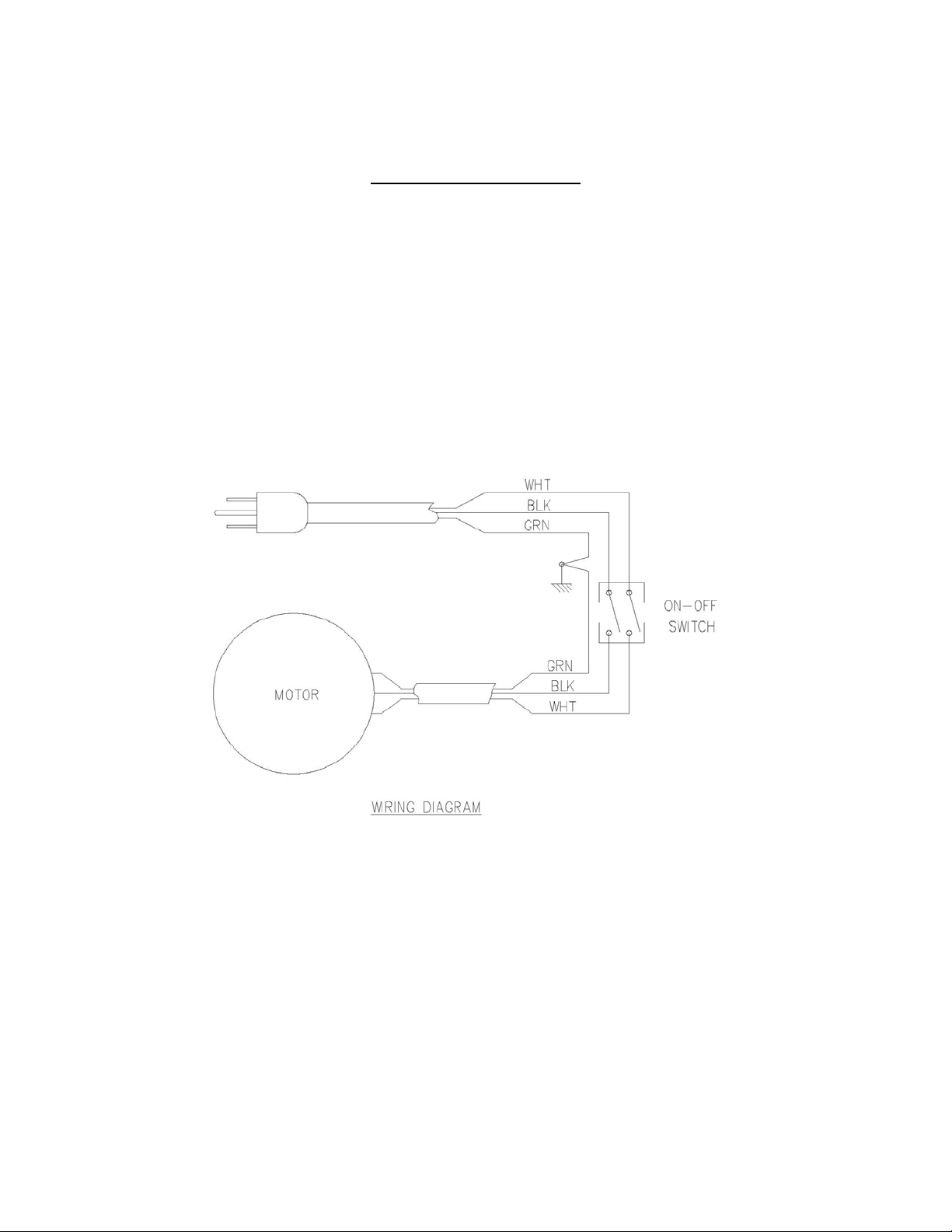
8
Figure 1—Wiring Diagram
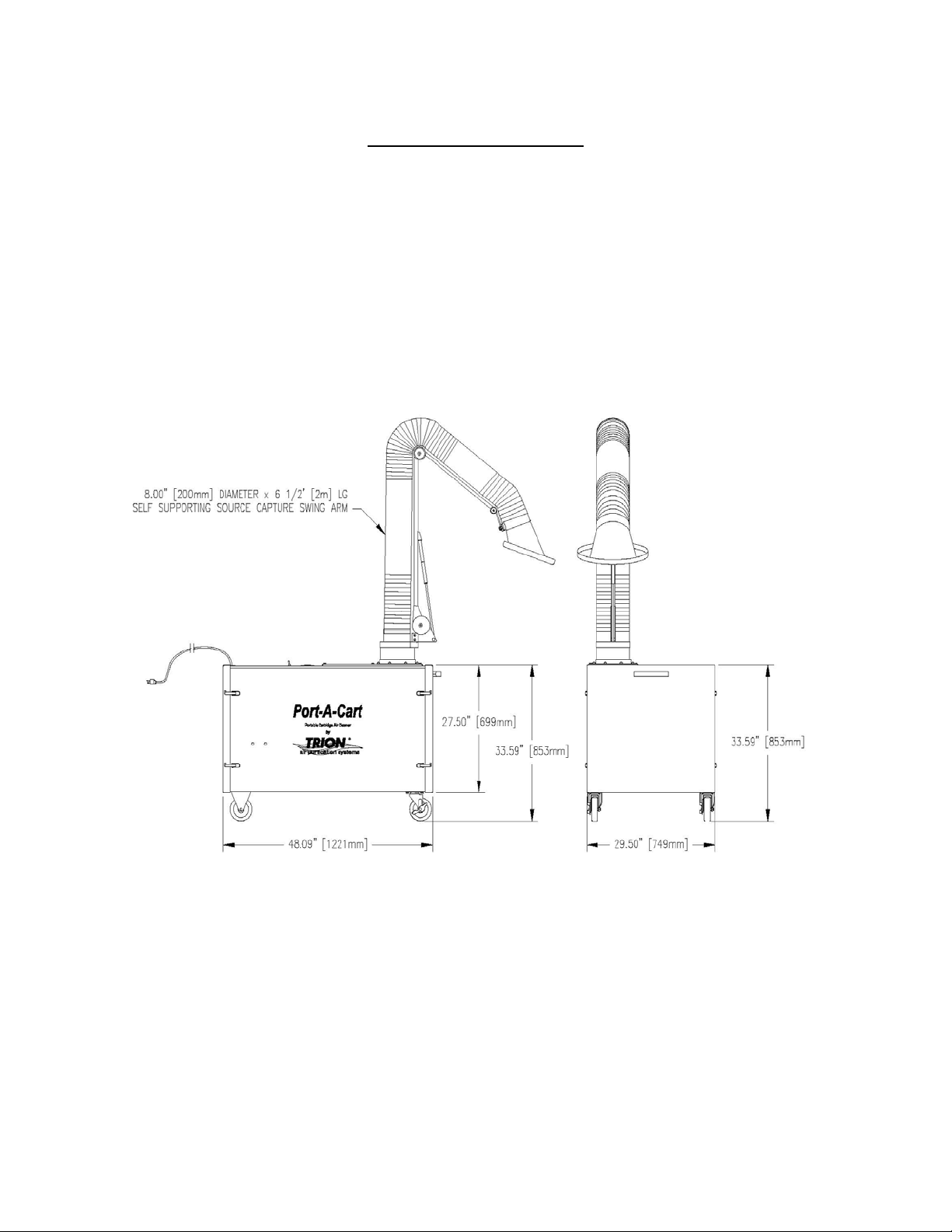
9
Figure 2—Outline Diagram

10
Reference Key Qty. per unit Part Number Description
1 1 251100-001 Cartridge Filter
2 1 145443-001 Minihelic Gage, 0-5”
3 1 150825-001 Motor, 1 1/2 Hp, 120/208-230 volt
4 1 250827-001 Blower Wheel
5 1 256941-001 Impregnated Carbon Filter
6 1 256950-002 Power Cord
7 1 238001-002 Toggle Switch, DPST
8 8 245386-017 Latch
9 2 252122-001 Caster, 5”, Fixed
10 2 252122-002 Caster, 5”, Swivel
11 1 354970-012 Fume extractor (pick-up) Arm
12 1 145439-003 Diaphragm Valve, 3/4” (optional)
13 1.33 147039-002 Hose, 1” ID (optional)
14 1 257214-001 Pushbutton Valve (optional)
PARTS LIST
See Figure 3
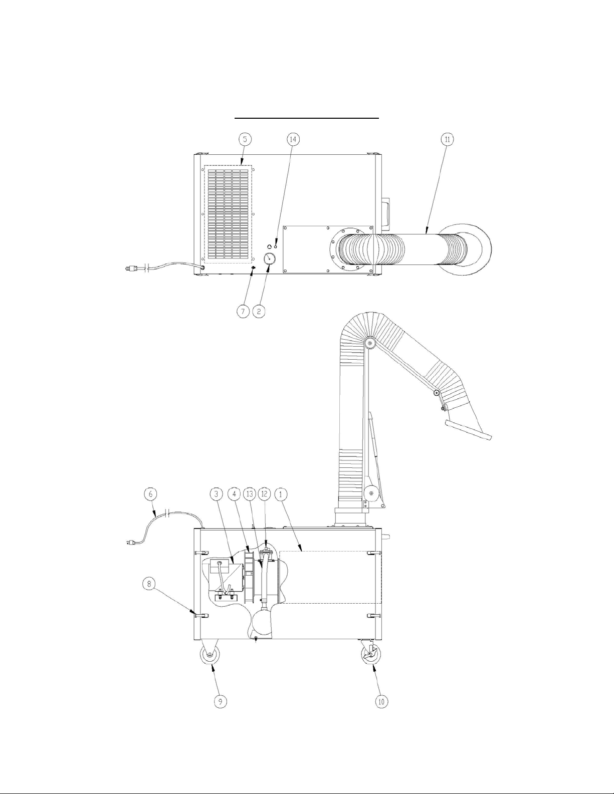
11
Figure 3-Parts List Diagram

12
Contact Information
Headquarters
Trion, Inc. Trion LTD.
101 McNeill Rd. The Cavendish Center
Sanford, NC 27330 Winnall Close
Tel. 919 775 2201 Winchester, Hampshire
Fax 919 777 6399 SO23 OLB, UK
www.trioninc.com Tel. 44 0 1962 840465
Trion GmbH Fedders International
Boscstr. 60 No. 728 Fuzhou Rd.
D-50171, Kerpen Rm. 3002-3005
Germany Raffles City Office Tower
Tel. 49 0 2237 922 103 Shanghai, P.R. China, 200001
Fax 49 0 2237 922 104 Tel. 86 21 63403232
Fax. 86 21 63403867
Fedders International Fedders International, Inc.
Air Conditioning 128 Joo Seng Road
A-30, Chintels House #05-01
Kalish Colony DP Computers Building
New Delhi Singapore 368 356
India 110048 Tel. 65 6286 0995
Tel.91 11 5173 0730 Fax. 65 6286 0859
Fax91 11 5173 0743
Table of contents
Other Fedders Air Cleaner manuals


