Fei Bao F-4 Phantom II User manual

F E I B A O F - 4 P H A N T O M I I
1
11
1
FEI BAO JETS
F-4 Phantom Assembly Manual
In collaboration with R C Jet Models

2
22
2
DISCLAIMER:
THIS IS NOT A TOY.
This is a high-performance miniature aircraft, capable of high speeds
and damage to life, limb, and property. The manufacturer and its distributors cannot control how
you assemble this model, what equipment you use to fit it out, or how you fly it, and can assume
no liability whatsoever for any damages that may occur when you fly your aircraft. By
assembling this model, you are agreeing to indemnify and hold blameless the manufacturer
and/or his agents from any and all torts and liability associated with the use of this product.
Once you have assembled the aircraft, you are the pilot in command and assume any and all
responsibility for the use of the model and any damages that might occur by flying or attempting
to fly this aircraft.
R/ model jets require a high level of skill in both their assembly and their flying. If you do not
feel confident in either your building or flying skills, PLEASE seek assistance from more
experienced modelers. It is a wise idea, no matter what level of skills you possess, to have a
second experienced modeler go over your installation after assembly. A second set of eyes may
spot a problem you have missed. If you have not flown a model like this before, it is HIGHLY
recommended that you get an experienced turbine pilot to do your maiden flight. Very often, the
first few seconds of a maiden flight are critical until the aircraft is trimmed out, and having an
experienced pilot at the controls can make the difference between a wrecked aircraft and once
that enjoys many hundreds of flights. Be sure to select a suitable field for flying...take the time
to find a large paved runway if at all possible, especially for test flights, until you feel comfortable
getting the aircraft in and out of smaller grass fields.
Congratulations on your purchase o the Fei Bao F4 Phantom II.
Be ore you begin
• lean and inspect all parts. Inventory them against the parts list at the end of the manual
and notify the kit supplier of any missing components as soon as possible.
• If the paint scheme you have selected is glossy, it is recommended that you apply a coat of
wax. This will help resist dirt, stains and fingerprints during construction, and will provide
some limited protection against errant glue.
•
Vacuum out the remnants of packing materials that remain in the fuselage.
While the kit is comprehensive, there are additional parts required, as follows:
• Recommended Servo List (JR)
• Elevators: (2) 8611a
• Aileron: (2) 8611a
• Flaps: (2) 8611a
• Rudder: (1) 3421
• Nose Steering: (1) 2721
• Retracts: (2) 351 or equivalent
• Brakes: (1) 351 or equivalent
• Other Parts
• BVM UAT (optional)
• ½ inch Velcro straps to secure fuel tanks
• Wire twist tie (optional)

3
33
3
• Blue Loctite
• Glues: Thin A, 5 minute epoxy, Aeropoxy
• Electronic gear sequencer
• Brake valve
• Batteries, regulator and switch
• Servo extensions (length may vary, depending on receiver placement)
Construction
The order o construction may be changed to suit your personal pre erence,
however, there are a ew points to note:
• The fuel system is more easily accessed if the fuselage halves have not been joined
• The model is more easily worked in a tight space if work is completed on each fuselage
section before they are joined
• The incidence of the main wheels must be set prior to attachment of gear doors, thus, the
fuselage should be completed before the wings.
The retract system in the prototype is operated by two valves. The two way valve controls gear
up and gear down. The gear doors stay open with the gear extended, so the door open-air lines
are simply connected to the gear down lines. The door close airlines are connected to a second
one way valve, which is operated by an electronic sequencer. The sequencer delays the
operation of the door close valve, allowing the gear to retract.
Step 1: Fuel System
onstruction begins with the fuel system. Once the nose is bolted on the aft fuse, the forward
fuel tank that sits between the intakes is more difficult to install, so now is the time to complete
this step.
It is recommended that you disassemble and inspect the tank cap hardware. As photo 1 shows,
the process used to cut the tubes may leave behind a rim that constricts fuel flow and could
result in excess tank pressure and leakage. The vent tube to the top of the picture shows what
the constriction looks like before repair, while the fuel tube on the lower left shows what the
tubing should look like after clean up. If the tubing is not constricted, skip forward to the leak
check.
Photo 1
Loosen the Philips head screw and remove the stopper assembly from the tank.
Use a small, round Perma-Grit rat tail file or an Exacto knife to remove the excess metal.
You will need to inspect the ends of all tubes.
4
44
4
The tube that the pickup line connects to inside the tank may also need to be shortened to
approximately 12 mm for ease of installation through the tank orifice. When finished, make
sure to blow out the metal fragments and clean up any sharp edges.
While the components are apart, check the Tygon pickup line for equal lengths in both saddle
tanks. They should be long enough to reach the back of the tanks without being so long as
to restrict their ability to move to the top of the tank when the aircraft is inverted.
You should also notch the vent tube with a small file to provide for continued air flow should
the tube come into contact with the top of the tank.
Make sure the bends to the vent tubes applied at the factory have not restricted airflow to
any significant extent. Also, check the Tygon for any nicks or cuts and secure to the tubing
with wire ties before re-assembly.
Once the tanks are back together, they should be leak checked before installation in the
aircraft. onnect extra lengths of fuel tubing to the fuel and vent lines and submerge the
tank in water. Pinch off one line and gently pressurize the tank by blowing into the other,
looking for signs of air bubbles. If the tank shows evidence of air leakage around the vent
cap, tighten the Philips head screw and check again. If you have a stubborn leak, you can
re-tap the inner plate for a slight larger 6/32 cap head bolt.
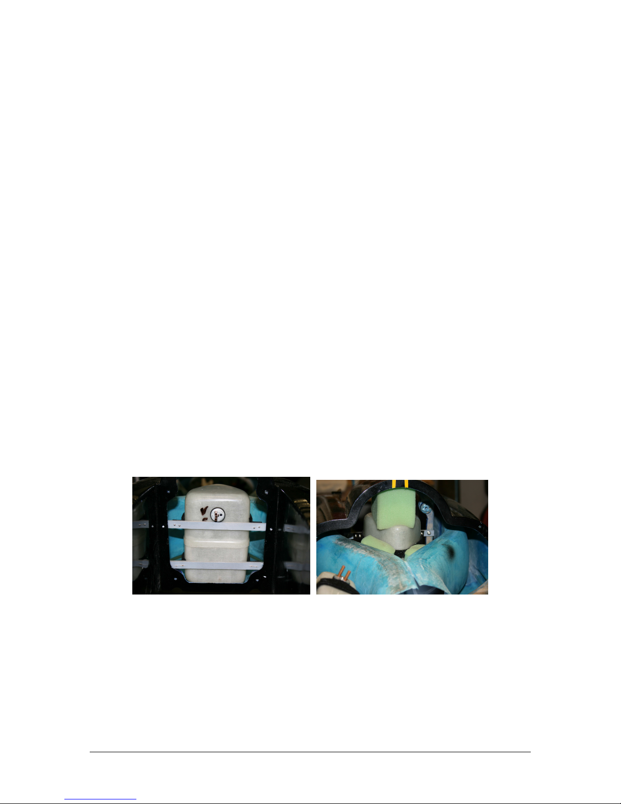
It is recommended that you mount the forward fuel tank so as to be able to remove it for
maintenance in the future.
Before installing the saddle tanks, check the spar receiver bolts to make sure the nuts are
secure. Plug the wings into the spar receivers and move them up and down, tightening the
locknuts until there is no evident play.
ut two strips of 6 mm ply approximately 180 mm long by 12 mm wide. Also cut four Velcro
straps approximately 12 mm wide by 180 mm long.
Using two 7mm wood screws per strap, attach two Velcro straps approximately 20 mm from
the end of each ply rail. Be sure to attach the straps so they overlap, holding the flat part of
the tank firmly against the ply rail.
The lower rail can be glued to the inside of the front former, but the upper rail should be
attached with screws accessed from the engine compartment such that the upper rail may be
removed. Strap the tank in place.
Photo 2 Photo 3
For extra security, place several pieces of scrap foam between the tank and the intakes, and
also between the top of the tank and the top of the fuse to keep it from shifting during flight.
To mount the saddle tanks, begin by routing two narrow 12 mm slots toward the outside of
the engine mounting rails. These should be positioned approximately 60 mm inside the front
and rear formers.
ut two Velcro straps 350 mm long and thread them through the slots. Position the saddle
tank with the curvature to the outside and the stopper assembly at the front, and tighten the
straps. The tank should be canted slightly inward to allow the fuel lines to clear the inside of
5
55
5
the hatch. Place a piece of scrap foam between the top of the tank and the side of the
fuselage to hold the tank in this position.
ut a piece of scrap balsa block to act as a spacer between the front of the tank and the
former. Make sure you can access the forward wing spar mounting bolts, and then attach
the spacer block to the front former with a drop of A.
Photo 4
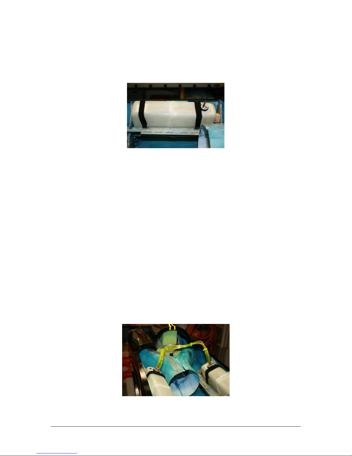
When you are happy with the position of the tank, test fit the hatch and check for clearance.
If everything checks out, glue the Velcro to the slots routed in the rail with 5-minute epoxy.
Also apply epoxy to the point where the Velcro strap meets the side of the fuselage, being
careful not to glue the tank to the strap. This will keep the tank from shifting.
Repeat all steps for the other saddle tank.
heck the fuel lines for nicks and cuts as you proceed through the next steps.
onnect two pieces of fuel tubing approximately 180 mm long to the fuel pickup tubes in
each saddle tank and bring them together with a “Y” fitting just above the intakes.
Repeat this process for the vent tubes in the saddle tanks.
Run a length of fuel tubing from the “Y” fitting connected to the fuel pickup tubes to the vent
tube of the main center tank.
Attach a length of tubing to the “Y” fitting connected to the vent tubes on the saddle tanks.
The vent fitting will be positioned in the forward fuselage … a pigtail of approximately 200
mm extending past the forward former should be sufficient.
onnect a length of tubing that will run to the fuel pump to the fuel pickup tube on the main
center tank.
Wire tie all connections at this time
If you use plastic wire ties to bind the fuel tubes together for a neater installation, make sure
not to over-tighten and pinch down on the flexible fuel tubing.
This completes the fuel system.
Photo 5

6
66
6
Step 2: Vertical Fin and Rudder
Before assembly begins, inspect the glue joints between the fin ribs and the outer skin. These
may be seen through the servo mounting hole and the forward inspection cut out. If there are
gaps in the glue, fill them in with a little Aeropoxy.
Mount the rudder servo, with the spindle toward the rear of the fin. You may need to
enlarge the mounting hole just slightly.
Photo 6
Using a JR Matchbox or your receiver, power up the servo and set it at neutral. Attach the
control arm at a vertical position. Enlarge the strut slot size in the fin slightly with a small file
if the arm binds.
Assemble the rudder linkage. Use the rod that is approximately 190 mm long. You will need
to enlarge the hole in the control horn with a 7/64 inch drill for the rod bolt. Do not over
tighten this bolt as the rod will bind as the rudder is actuated.
Photo 7
onnect your servo extension and secure with tape or heat shrink tubing.
Secure fin to aft fuselage with 12mm bolts and large 12mm washers. Use Loctite on the
threads.

7
77
7
Step 3: Horizontal Stabilizers
heck the nuts that bolt the stab bearings to the stab plate for tightness. Also make sure the
stab bearing covers are glued securely to the stabs. Reinforce if necessary.
File the slots in the fuse side to give the stab as much throw as possible.
Photo 8
Temporarily place the stab plate back into position in the fuselage.
Find the 115 mm linkage rods for the stabs. Make sure the rod end (with the bolt) is
completely screwed on to the linkage. Tighten the locknut.
Optionally, you may choose to stiffen the linkage by slipping an appropriately sized brass
sleeve over the linkage, between the locknuts.
Screw the clevis on the other end of the linkage rods. Make sure the two linkages are of
exactly equal length, and then tighten the clevis locknut.
Mount the aluminum L brackets to the elevator servos. Do not use the rubber damping
pieces that come with the servo. Use washers and red Loctite on the screws. Also check to
make sure the brackets are positioned so that the servo will sit flat on the mounting plate.
Make sure the servos mirror each other in a left and right set.
Using a JR Matchmaker or your receiver, find neutral for the servos and experiment with
servo arm orientation that results in matching positions. ut off the opposing arm and then
mount the arm to the servo.
Photo 9
8
88
8
onnect the clevises to the servo arms. Don’t forget the locking clips.
Screw the rod end bolts into the bearing plate arms, from the outside in. Slip the clevises in
place and position the servos on the servo mounting plate.
Photo 10
With the servo arms in a vertical position, and the stab set for a slight bit of up elevator,
mark the position of the mounting brackets.
Remove the servos and linkages. Unbolt the servo mounting plate and remove it.
Align the bottom of one servo to the exact edge of the ply plate, with the bracket on the
alignment mark you made in the previous step. Using 12 mm wood screws, bolt the
aluminum brackets to the ply plate.
Working carefully, position the other servo with the output spindle exactly opposite the first,
and the bottom of the servo aligned with the edge of the ply plate. Drill and screw this servo
to the ply board.
Now would be a good time to attach your servo extensions, using tape or heat shrink to
secure. Do not “Y” the servos, as they will be adjusted in a later step. If you are using a JR
Matchbox, it must be within 6 inches of the receiver, so two long extensions from the
elevator servos are a requirement.
Remove the stab from the fuselage. Insert the servo plate back into position and bolt it into
place with 20 mm bolts and 12 mm washers. Loctite.
Replace the stab into the fuselage and permanently bolt into place using 20 mm bolts and 12
mm washers. Loctite.
Temporarily connect the linkages to the metal arms, but do not tighten them, as final servo
adjustment will be required after installation of the receiver.
Using wire ties or wire loom, secure the rudder and elevator extension wires together.
Notch several small blocks of wood for plastic wire ties, and glue these along the top of the
fuselage well away from the pipe with 5 minute epoxy. Roughen the surface of the fuse
before gluing.
When dry, secure the cables to the blocks with wire ties.
Photo 11
9
99
9
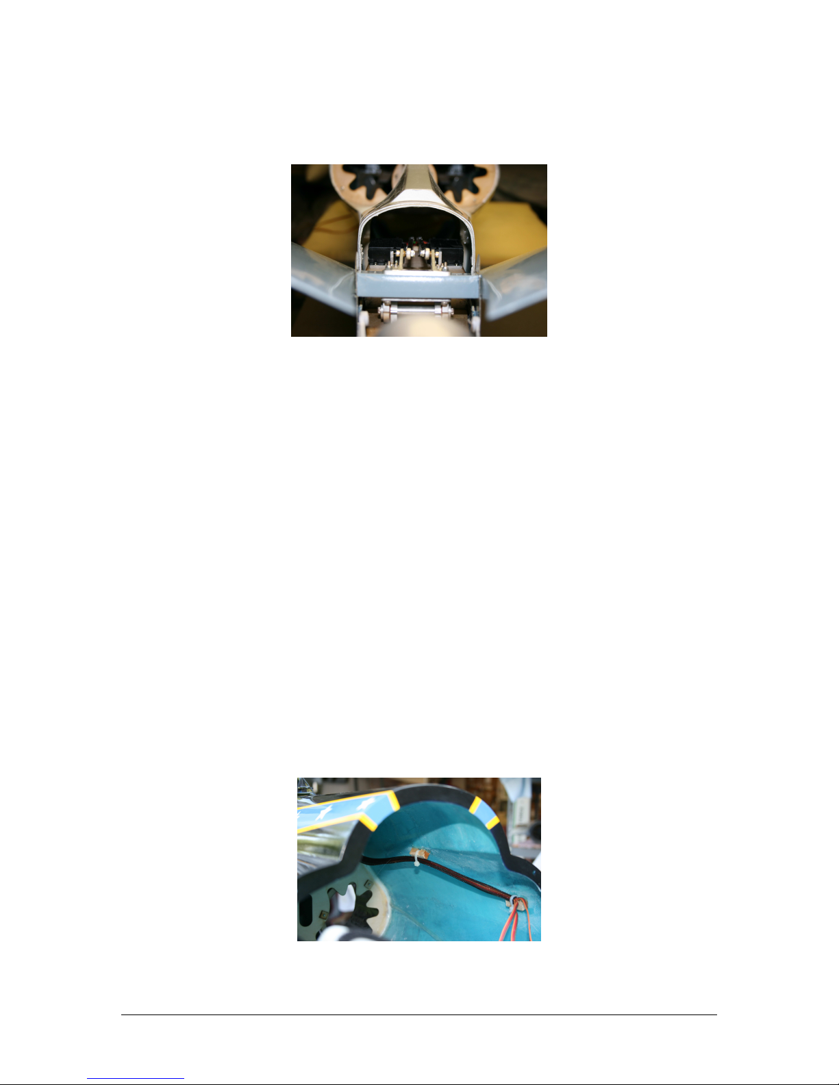
Step 4: Tail Accessories
Trial fit the lower stab cover and trims if necessary. Temporarily attach to the fuse with flat
head screws.
Photo 12
Bolt the exhaust cones to the aft firewall.
Attach the tail hook. Roughen both surfaces to be glued and drill small holes in both parts to
act as glue “pins”. Use Aeropoxy, being careful to keep it away from the edges of the hook.
lean up any glue that seeps out immediately. Tape in place and set the aft fuselage aside.
Gently move the stab by hand and check for binding. If any is evident, take corrective steps
at this time.
This completes the aft fuselage work.
Photo 13
Step 5: Nose Doors
You will be hooking up airlines in the next section. There will be three primary connections
required: (1) gear up, (2) gear down/doors down and (3) doors closed. The system will be
operated by two valves. The primary valve will activate gear up and doors open/gear down. The
secondary valve will control the closing of the gear doors and will be delayed through use of
sequencing.
It is convenient to set the nose section on end when working through the following steps.
Inspect all of the gear door hinge and air cylinder mounting bolts for security. Put a small
drop of thin A on the gear door hinge bolts to prevent loosening of the nuts. The forward
gear door cylinder will not be attached to the forward door … this will be completed in a
subsequent step.
Reinforce the hinge to fuse joints with a little Aeropoxy for added security. Be careful not to
get glue into the hinge mechanism.
10
1010
10
Loosen the four retaining bolts and remove the forward door. Replace the screws in the
fuselage to avoid losing track of them.
Now is a good time to run airlines to the nose door cylinders while there is a little space to
work. Test for leakage and proper operation of the valves as you go, using a hand pump.
Secure the lines together with plastic wire ties to keep them organized and out of the way.
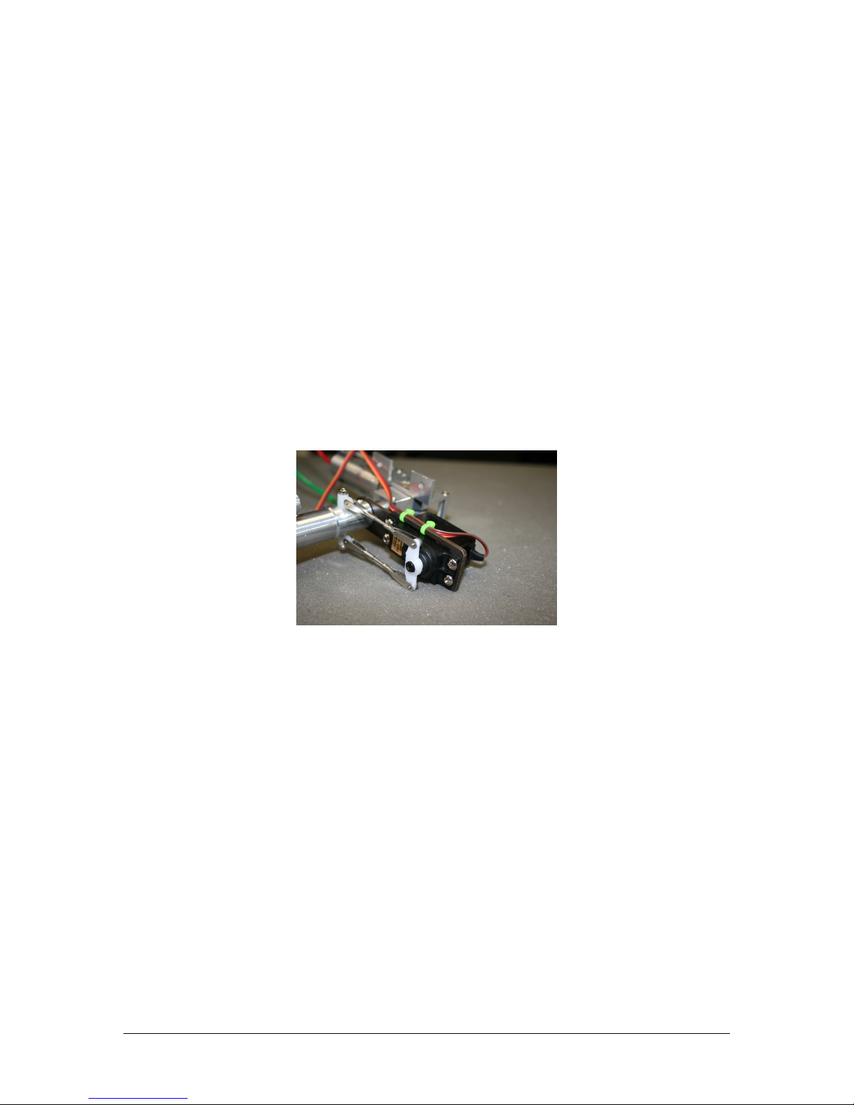
Step 6: Nose Retract Unit
Insert the retract servo from the bottom of the mounting plate, with the spindle toward the
outer end of the bracket.
Attach the servo using the bolts provided. Loctite.
Using your receiver or a Matchmaker, find neutral on the servo and mount the arm.
Attach clevises, making sure they are not so tight as to cause binding. Using plastic wire
ties, secure the servo wire well away from the end of the bracket. This area of the bracket
will pass close to the former as the retract is operating.
One at a time, remove the strut set screws, apply Loctite and reassemble, making sure they
are snug.
Attach your air lines and test the retract unit with a hand pump, making sure it will hold air
and operates smoothly.
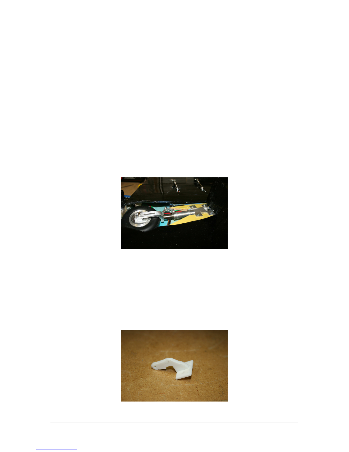
Photo 14
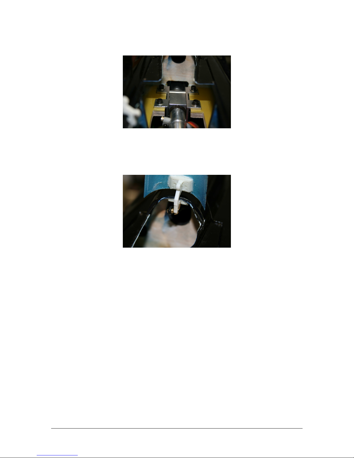
Position the retract unit into the retract plate from the bottom. The front of the retract unit
should be positioned approximately 10 mm behind the front former. Insure this is enough
to clear the front door when installed and that the wheels clear the aft door opening. Mark
this position with a felt pen.
Working carefully to make sure the retract unit stays in this position and aligned equally to
either side of the gear opening, drill one of the holes closest to the forward former. Insert a
bolt into the hole to hold this position.
Proceed to drill the other three holes, making sure to maintain alignment of the gear. Insert
a bolt in each hole as it is drilled.
When all four holes are drilled and you are satisfied with the alignment, remove the retract
unit.
Drill out each hole to be large enough for a blind nut. Insert these from the top and snug
them down with one of the bolts. Apply a little A to the back of the blind nuts sparingly to
hold them in place.
11
1111
11
Reinsert the retract unit and bolt in place. Loctite.
Photo 15
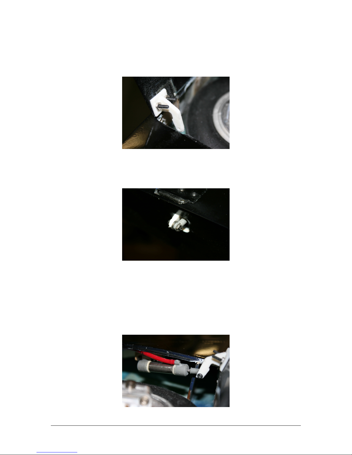
Remove the mounting lugs from the rear most door hinge to help with hinge clearance as the
gear swings into the retracted position.
Reinstall the nose gear door.
Attach the cylinder to the nose gear door with a small cotter pin.
Photo 16
heck the nose gear door to make sure it opens sufficiently to allow the nose gear to extend
fully without binding on the door. Trim the bottom of the door if necessary.
It will aid in the removal of the nose gear if you use quick disconnects on the air lines to the
retract unit. Use a servo clip on the steering servo as well, rather than taping or heat
shrinking this connection.
Remove the component board and set aside, if this has not already been done.
lean the forward fuselage section thoroughly.
Step 7: Joining the Fuselage
Inspect all the mounting holes to insure they are free from debris. Try the bolts and make
sure they all thread easily.
arefully position the nose section between the intakes. It will be a tight fit, so work
carefully and slowly. Do not force the section in place.
Using the 20 mm long bolts and large washers, bolt the two main bulkheads together.
Using smaller 10 mm bolts and the large 12 mm washers, secure the side sections to the
intakes.

12
1212
12
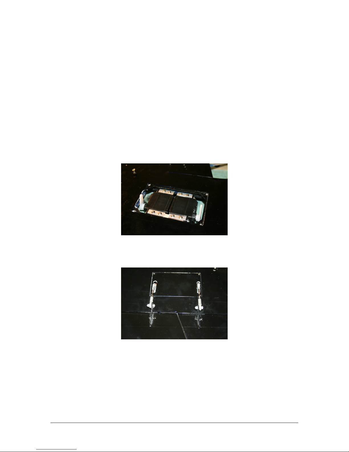
Step 8: Component Board
Trim the edges and back of the component board so that you can easily fit it through the
canopy hatch.
A suggested layout of components is shown in photos 17 and 18. This arrangement allows
easy access to the receiver and servo wires, provides good separation between the turbine
and receiver electronics and sits low enough for the cockpit to easily fit on top.
Photo 17
Photo 18
Make sure to keep the area just in front of the forward former clear of wires and airlines for
retraction of the steering servo. The nose wheels will fit right up against the bottom of the
component board when retracted, so it is recommended you have nothing extending below
the board in this area.
Now is a good time to complete installation of all servo extensions, airlines and turbine
electronics through the fuselage.
Step 9: Engine and Pipe
lean the fuselage thoroughly before installing the engine. If you need to trim the intake for
engine clearance, use a vacuum while you work. This will reduce the chance of having a foreign
object finding its way into your engine.

13
1313
13
Drill two holes on each side of the pipe mounting tabs. The first should be just in front of
the pipe mouth, the other approximately 50 mm further forward.
The tabs are positioned just above the centerline of the pipe and this is the top. Insert the
pipe into the fuselage and position the aft end about 5 mm from the end of the exhaust
cones.
Photo 19
Place the lower bypass on the engine mounting rails. Slip the pipe forward over the aft end
of the bypass. You may need to slightly trim the lower former a bit to allow the bypass to
move far enough aft to keep the rear of the pipes in position.
Position your engine on the mounting rails. Set the gap between the rear of the exhaust
cone and the mouth of the pipe to manufacturers specifications. This is usually around 20
mm. You may need to trim some material off the intakes to allow the engine to sit far
enough forward.
If required, marks the bypass for the positions of the engine mounting tabs and trim away
material such that the engine exhaust is centered on the pipe. Shims may be required under
the front engine mounting tab to insure that the angle of the engine is on line with the angle
of down thrust of the pipe.
When you are satisfied, bolt the engine to the side frames with appropriately sized wood
screws. Install the screws and then remove. oat the thread holes with thin A. This will
harden the wood around the screw holes themselves. Permanently reinstall the engine
mounting screws.
Drill and secure the bypass to the engine mounting rails with four wood screws.
Finally, drill the rear of the bypass for the pipe mounting straps and bolt in place. The heads
of the bolts should be on the inside of the bypass.
onnect fuel, gas and electrical lines up to the turbine.
Photo 20
14
1414
14
Step 10: Wing Servos
Remove the servo cover. Mark the inside front of the door so you will know how to orient it
for reassembly.
Attach the aluminum L brackets to the servos as you did for the elevators. The servos will
face in opposite directions and the servo spindle is positioned toward the rear of the wing.
Using your receiver or JR Matchmaker, find servo neutral and attach the heavy-duty servo
arm.
Enlarge the servo wire hole in the wing root to accommodate the two servo wire connections
and four air quick disconnects.
Label the servo wires for aileron or flaps.
Position the servos onto the mounting tabs. If you are using 8611a servos, you will need to
make a shim plate for the rear tabs to hold the servo just slightly off the top of the wing. If
you omit this shim, you will deform the top of the wing as you tighten the bolts.
You may also need to trim the lip of the servo well slightly to provide clearance for the
aileron servo arm.
Using great care not to pierce through the top of the wing, drill and bolt the servos in place.
Photo 21
Trim the servo cover for the servo arms and reinstall.
onnect the 70 mm linkage arms, following the same procedure used for the elevators.
Photo 22
Repeat for the other wing. Be sure to keep the linkage lengths equal.
15
1515
15
Step 11: Main Landing Gear
Install airlines on the retract units.
heck for air leaks and smooth operation of the retracts with a hand pump.
Insert the gear into the mounts and extend the gear. The wheels should be set to just a
slight amount of toe in compared to the wing root. A setting that just allows the inner door
to close over the wheel will be very close.
Retract the gear. The outboard end of the retract unit should be positioned up against the
former and the wheel itself should just clear the aft end of the wheel well. You need some
clearance in front of the wheel for the door activating cylinder placement.
If the wheel hits up against the wing root with the retract unit positioned as far outboard as
possible, you can remove one of the clips and open up the scissor assembly to access the
adjusting screw. Rotating the adjusting screw counterclockwise will shorten the gear stance.
With the wheel and retract unit in position, carefully drill one of the holes and mount the
retract in place. Again, be careful not to pierce the top of the wing.
At this point, mount the wings temporarily on the fuselage and set the final incidence. heck
again to make sure the inner door will close fully over the wheel.
When you are satisfied with the position of the gear, drill and install flat head screws in the
remaining holes.
Photo 23
heck for any binding and trim the door lip a little if necessary.
Step 12: Inner doors
If not already done at the factory, secure the forward hinge to the ply backing plate with four
short button head screws. This reinforces the hinge that will take the brunt of the force
from the door cylinder.
Photo 24
16
1616
16
for the bolt you will use to attach this door actuating ar to the cylinder end.
Temporarily bolt the door-actuating arm to the door, aligned with the lower forward corner of
the door (photo 27). Use a drop of Aeropoxy to help secure it. Put a drop of thin A on the
nuts and remove the excess bolt length, if any.
Photo 27
arefully route a hole in the wing root to allow the door-actuating arm to move through as
the door closes. You will also need to trim a little off the lip of the wheel well for the door to
close completely.
Photo 25
Attach the door cylinder to a scrap ply block approximately 15 X 25 mm. The cylinder
included with the kit may differ a little from the one shown in the photos, but the mounting
will be similar.
Bolt the cylinder end to the modified hinge. Due to the angles involved, you will need to
keep this connection somewhat loose to prevent binding.
Rough up the wheel well surface where the cylinder-mounting block will be glued with 100
grit sandpaper.
Position the door fully open and glue the wooden block in place, taking care to make sure
there is adequate clearance for the wheel to clear the cylinder.
Photo 29

17
1717
17
Add an Aeropoxy fillet around the wooden cylinder-mounting block.
If the door wants to open too far, you can add a small scrap of wood between the cylinder
end and the bottom of the wing to prevent it from flexing upward.
Route and secure the airlines and add quick disconnects.
Repeat these steps for the other wing.
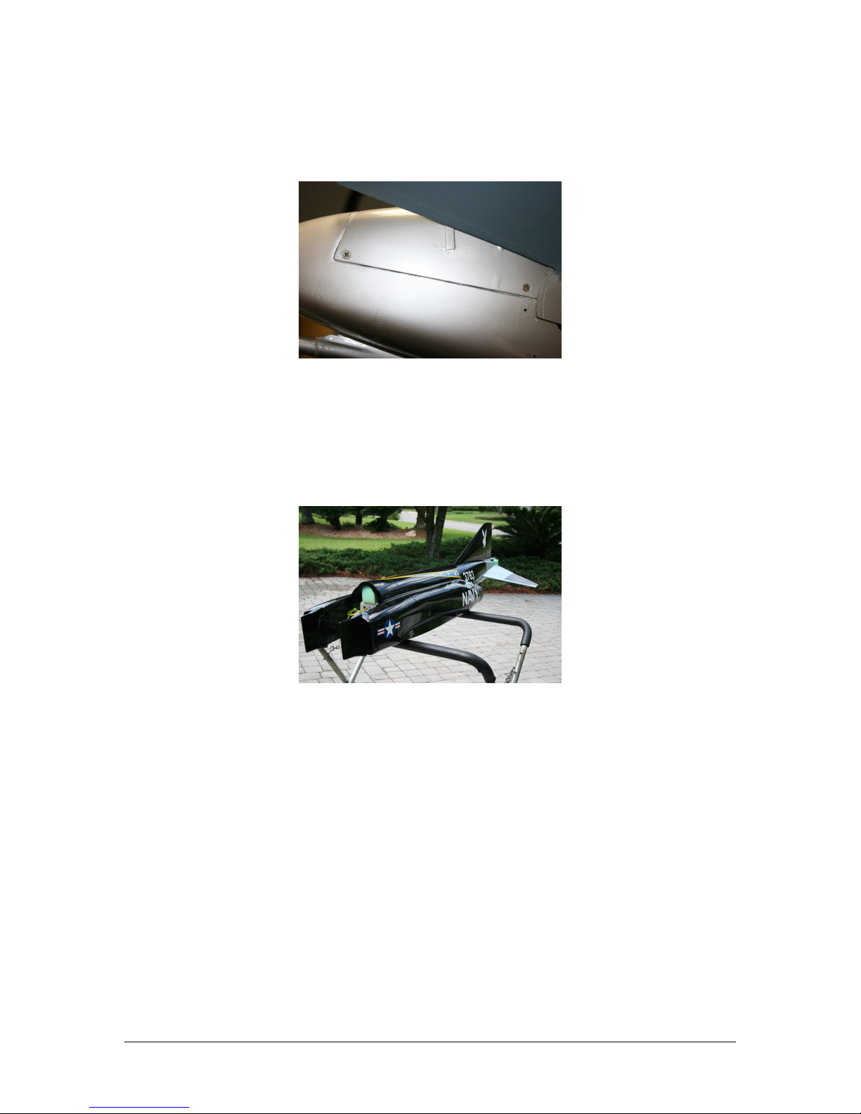
Step 13: Strut Covers
Retract the landing gear and clean the portion of the strut that the strut cover will attach to
with solvent.
ut a piece of scrap ply approximately 10 mm wide of the appropriate depth such that it fills
the gap between the strut and the strut cover with the strut retracted and the cover in place.
Glue this piece to the strut cover with 5 minute epoxy.
Now apply Aeropoxy to the strut side of the wood piece and position the door in place. Tape
and allow the glue to dry overnight.
Extend the gear carefully and position the metal mounting bands around the strut. Drill
through the strut cover and bolt the bands in place. Use a little silicon-based glue on the
inside of the band to reinforce the attachment to the strut.
Photo 26
Step 14: Outer Doors
Reinforce the hinge attachment with two small button head screws. These should be
positioned at the lower part of the hinge, screwed in from the outside of the door.
You will need to attach a length of phenolic material or very thin ply to the bottom edge of
the door so it sits on top of the strut cover. This will prevent the strut cover from “catching”
on the outer door when the gear is extended.
Drill and tap the strut for a 2-56 ball link. The link is positioned in the center of the lower
strut band facing the rear of the aircraft, parallel with the outer door (photo 31).
ut a small mounting block, approximately 5 X 5 mm, from a piece of scrap ply. Mount
another ball link. The block should be just thick enough for the link. If you make it too
thick, the outer door will not close fully.
Tack glue this assembly approximately 42 mm up from the bottom edge of the door, in line
with the ball link attached to the strut.
Make a double looped link from carbon fiber thread or thin cable. You will need to
experiment a bit, but a good starting point is a length that holds the outer door up against
the strut cover.

18
1818
18
Photo 27
When you are satisfied with the operation of the outer door, add a fillet of Aeropoxy around
the wood block.
lean up any excess glue from the struts and use a bit of touch up paint as necessary.
Run the brake lines, making sure they don’t interfere with the operation of the retract units
or doors.
Step 15: Cockpit
Now is a good time to install your batteries. In the prototype, these were attached to the
nose gear plates on either side of the nose retract. If the air tanks have not been installed
yet, place them in the nose, packed in foam.
The glare shield should not be mounted permanently to ease maintenance in the future. It
can be attached with duct tape from the inside, or if you prefer, several small dabs of silicone
glue.
The cockpit tub comes pre-trimmed, and should simply drop into place.
The canopy also comes pre-fit at the factory and should be latched in place.
Step 16: Radio Programming
The prototype was set up on 10 channels as follows:
Throttle
2 aileron
2 flap
Rudder
Elevators (use matchbox)
Nose gear steering
Brakes
Retracts
Make sure the elevator linkages are disconnected when you turn the radio on for the first time.
Begin by reversing and programming one servo, and then match the operation of the other servo
to the first, using the instructions that come with the Matchbox.
Once you are satisfied with the programming of the elevator linkages, reattach the hatch
cover with flat head screws.
Find the four small curved swash plate covers. If these have been predrilled at the factory,
match the covers up with their respective holes and screw in place with small button head
screws.
heck the operation of the elevators one last time for freedom of movement.
Step 17: CG and Control Throws
19
1919
19
Set the enter of Gravity approximately 290 mm rear of the leading edge of the wing. The
G should be determined after the plane has been filled and drained of fuel, with the gear in
the extended position.
It is likely that nose weight will be required. One easy way to accomplish this is to tape the
required lead weight to the end of a basswood stick and insert fully to the front of the nose.
Secure the basswood piece to one side of the front former with a screw. This will make it
easy to remove and reinsert the ballast weight as you fine tune G.
Flaps, rudder and elevator should be set to maximum servo throws possible without binding
for the first flights. Elevator throw will be in the 45-50 mm range in both directions. Set the
elevator for a small amount of up trim for the initial flight.
Aileron throw should be approximately 40 mm in each direction for the first flight. Adjust this
in subsequent flights to suit your flying style.
Maintenance Tips:
To keep the stabs from moving during transport, wedge pieces of scrap foam between the
stab and fuse sides.
Remove the lower stab cover occasionally and inspect the stab mounting bolts for security.
heck the stab for excessive play before each flying session.
Inspect the inner door cylinder bolt each time you mount the wing.
When inverting the aircraft, put a short piece of fuel tube with a plug on the drain fitting.
This will prevent fuel from leaking into the missile rail channel and then into the seam
between the forward and rear fuselage sections.
ycle the gears before each flying session, checking for binding and proper door operation.
heck the struts for play, indicating the clamping set screw needs to be tightened.
Congratulations, you have completed construction on your Fei Bao F-4
Phantom II. See step 17 or balance and control throws.
Table of contents
Other Fei Bao Toy manuals

Fei Bao
Fei Bao F-9F Panther User manual

Fei Bao
Fei Bao Mirage 2000 User manual

Fei Bao
Fei Bao MB-339 User manual

Fei Bao
Fei Bao EF2000 User manual

Fei Bao
Fei Bao Velox User manual

Fei Bao
Fei Bao MiG-21 Fishbed User manual

Fei Bao
Fei Bao L-39 User manual

Fei Bao
Fei Bao F18-f User manual

Fei Bao
Fei Bao hawker hunter User manual

Fei Bao
Fei Bao T45 User manual


Popular Toy manuals by other brands

LEGO
LEGO CITY 60110 Building instructions

Fisher-Price
Fisher-Price OVERHEAD GYM W0128 instruction sheet

Fisher-Price
Fisher-Price M9974 quick start guide

Tiger Electronics
Tiger Electronics Sabrina's Psychic Phone 04-102 instruction manual

Apogee
Apogee Midge user manual

Fisher-Price
Fisher-Price PowerMax Rescue Heroes Billy Blazes Firefighter... instruction sheet


