Fei Bao T45 User manual

DISCLAIMER:
THIS IS NOT A TOY. This is a high-performance
miniature aircraft, capable of high speeds and damage to
life, limb, and property. The manufacturer and its
distributors cannot control how you assemble this model,
what equipment you use to fit it out, or how you fly it, and
can assume no liability whatsoever for any damages that
may occur when you fly your aircraft. By assembling this
model, you are agreeing to indemnify and hold blameless
the manufacturer and/or his agents from any and all torts
and liability associated with the use of this product.
Please inspect all parts before beginning assembly. If
any parts appear to be suspect, contact your dealer or the
manufacturer for repair or replacement BEFORE you
begin. Once you have assembled the aircraft, you are
the pilot in command and assume any and all
responsibility for the use of the model and any damages
that might occur by flying or attempting to fly this aircraft.
R/C model jets require a high level of skill in both their
assembly and their flying. If you do not feel confident in
either your building or flying skills, PLEASE seek
assistance from more experienced modelers. It is a wise
idea, no matter what level of skills you possess, to have a
second experienced modeler go over your installation
after assembly. A second set of eyes may spot a problem
you have missed. If you have not flown a model like this
before, it is HIGHLY recommended that you get an
experienced turbine pilot to do your maiden flight. Very
often, the first few seconds of a maiden flight are critical
until the aircraft is trimmed out, and having an
experienced pilot at the controls can make the difference
between a wrecked aircraft and once that enjoys many
hundreds of flights. Be sure to select a suitable field for
flying...take the time to find a large paved runway if at all
possible, especially for test flights, until you feel
comfortable getting the aircraft in and out of smaller grass
fields.
BEFORE YOU BEGIN:
Keep this in mind as you proceed:
Look at EVERY assembly step you finish, and ask
yourself:
"Is this going to crash my airplane?"
A chain is only as strong as its weakest link, and this is a
high-performance aircraft that will be very intolerant of
sloppy assembly techniques. Even the smallest
component is important and can cause the loss of your
FEI BAO T45
1

airplane, so take the time to do things right. Or REdo
them if they are wrong. Careful work will result in a long-
lasting plane that gives you years of pleasure, one loose
component could result in the complete loss of the aircraft
and all the components inside it, and someone can even
get hurt. So pause every once in a while when building it
and double-check your workmanship.
A. Introduction:
You have chosen a model that represents the pinnacle of
ARF technology. While there is not a lot of building to do,
there is enough to keep you busy for a few evenings.
Even if you have assembled maybe other ARF jets, we
highly recommend following our assembly sequence and
procedures anyway.
Chances are it will save you a lot of time, prevent you
from running down dead ends, and perhaps remind you
of a few small things that might end up saving your
aircraft.
We have tried to arrange a construction sequence that
will allow you to keep moving forward, rather than
standing around waiting for glue to dry before you can
proceed to the next step.
Just because the model is almost completely built does
not mean you can rush through the final assembly.
You need to employ fine craftsmanship every step of the
way, turbine models are critical. Keep this in mind with
everything you do, every part you install...look at the work
you just did, evaluate it critically, and ask yourself "is this
going to potentially crash my airplane?" If there is any
doubt about the work you have done, back up, and re-do
it properly.
B. Adhesives:
The correct adhesive to use for all procedures is Loctite
Hysol 9462. This is a very strong white epoxy that is
thixotropic. "Thixotropic" means it does not run at all, but
stays only where you put it. It is infinitely superior to
regular epoxy, even slow-setting epoxy, for our purposes,
because of this characteristic.
Regular epoxy will run downhill with gravity as it dries,
taking it away from where it is supposed to be.
A good example is in the hinges...using regular epoxy, a
good portion of the glue will migrate down away from the
hinge into the inside of the wing as it dries, and you won't
even know it is happening. Hysol stays where you put it.
The downside of Hysol is it takes overnight to dry
properly, but we have tried to arrange things to keep you
busy while waiting for glue to dry.
We also highly recommend that you only use a proper
Hysol dispensing gun, and only the long-type mixing
nozzles.
The short nozzles do not mix this glue enough, and only a
thin nozzle and gun will let you fill the hinge and control
horn holes properly with glue, you can't do it mixing your
Hysol on a flat surface and trying to get the glue in the
proper place by a brush or stick.
You can buy a complete Hysol setup with a gun, nozzles,
and two cartridges of glue from your dealer for
approximately $60.
FEI BAO T45
2

Consider it a great investment, the glue is the best you
will use. One cartridge is plenty to assemble your T45.
C. WORKING WITH PNEUMATIC SYSTEMS:
The T45 uses pneumatic brakes and retracts. If you
follow a few tips, you should have very reliable, leak-free
operation. Neatness counts.
All airlines should be secured to the airframe to keep
them from flopping around or getting kinked. Use tie
wraps for this.
The other very important thing is to cut off the end of each
airline dead square before installing it on the nipple.
This is VITAL. You can either purchase a professional
tubing cutter from your dealer (they are approximately
$10), or you can make up a little jig to hold the airline and
keep a sharp, new razor blade perfectly upright as you
cut.
Either one works, just ensure that all ends of all airlines
are cut off dead square. Make sure all airlines are
pushed ALL THE WAY onto their nipples.
They should not need to be secured otherwise, but you
can add fine wire safety wraps if you like. Make sure all
left and right matching airlines are the same length,
particularly the brake lines, or you will get uneven
retraction or braking action.
It's worth taking the time to get everything pneumatic right
the first time, as having your landing gear fail to retract is
not THAT bad, but having it fail to deploy can really ruin
you day and the paint on the bottom of your model.
Sample Servo List:
Ailerons and Rudder: JR 3421 (3)
Flaps: JR 8611A (2)
Elevators: JR 8611A (2)
Nose Gear Steering: JR 8411
Air and Brake Systems: As necessary
Parts List:
•Forward Fuse with Component Boards and Nose Gear
•Aft Fuse
•Canopy
•Cockpit Tubs (2) and Glare Shield
•Main Upper Hatch
•Lower Aft Hatch
•Ventral Fin
•Tail Hook
•Wings, Main Gear, Ailerons and Flaps
•Wing Tube
•Aileron and Flap Covers (4)
•Vertical Stab and Rudder
•Horizontal Stab Strakes
•Wing Fences (2) (Not used on T45)
•Fuel Tanks (2)
•Bypass
•Pipe
•Air Kit
•Hardware Kit
FEI BAO T45
3

Construction
Carefully inspect all components. Check the security
of all bolts and nuts. Seal with a small amount of thin
CA for extra security. If any of the stab bearing plate
bolts are stripped, re-tap holes and replace with 6-32
cap head bolts. Reinforce bearing plate and stab
former with extra Aeropoxy. See photos
Join Fuselage Halves
Position front of fuselage to rear of fuselage. Loosely
secure in place with four XXX bolts and washers at
the aft attach points and two XX bolts and large
washers on the side attach points. Use Loctite.
Position top hatch in place and fit canopy. When
everything aligns, permanently tighten 6 bolts.
FEI BAO T45
4
Horizontal Stabilizers
Remove lower hatch and set aside.
Slip one large and one thin nylon washer on the stab
spar and insert into bearing box. Check for at least
40mm throw as you move stab. Use the minimum
number of nylon washers to achieve clearance.
Tighten and loosen control horn bolts one time to ease
installation.
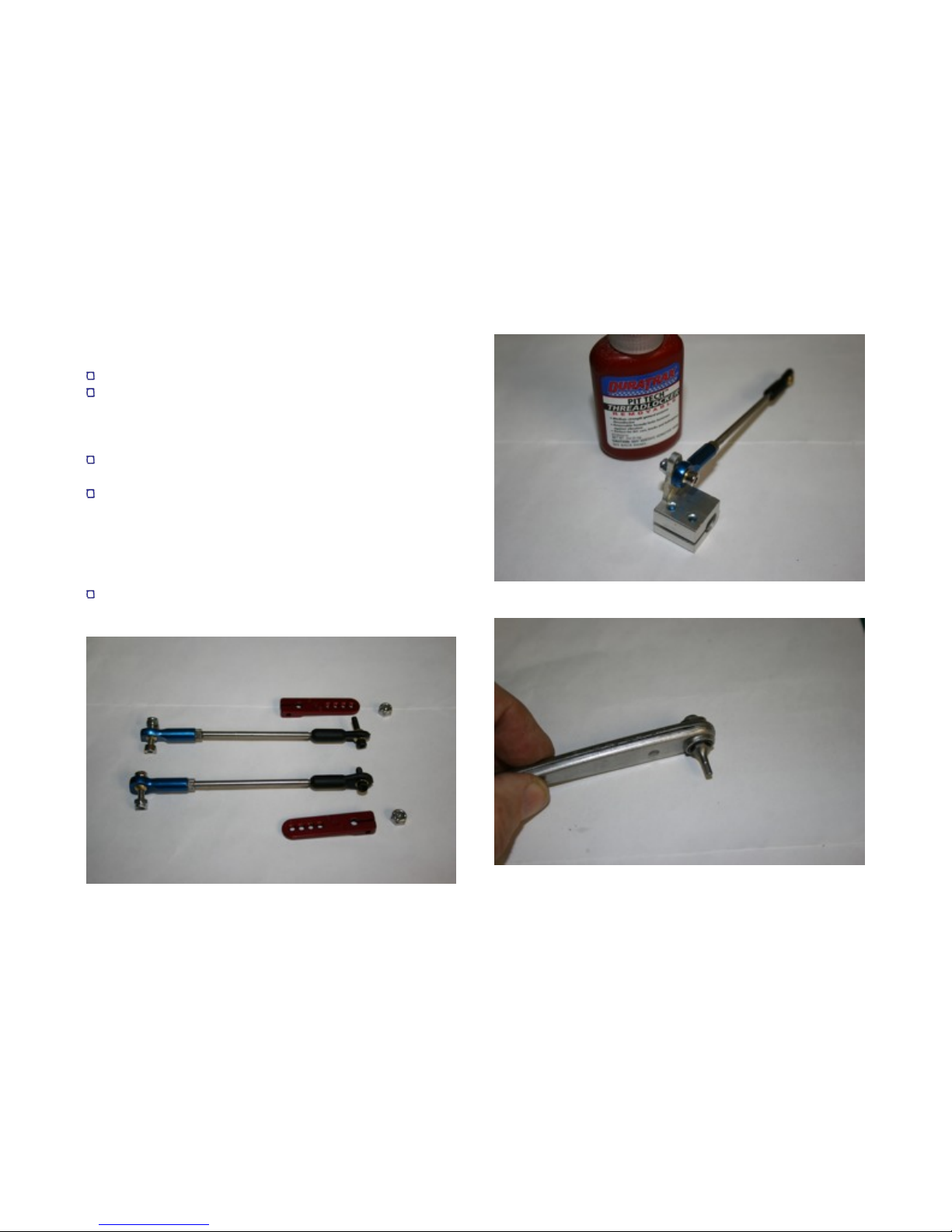
Option: you may choose to replace the FB clevis with
a heavy duty ball link (see pictures). If so, drill out the
middle hole on the control horn for the bolt that will
attach the titanium FB ball end to the horn now. Use
the wire size drill that is just large enough to insure the
bolt will fit with no play.
To tighten the horn bolts, you will need an allen
wrench, an allen bit (see photo) and patience!
FEI BAO T45
5
Slip a nylon washer over the end of the stab spar.
Loctite snugging bolts and tighten just enough that
control horn will barely slide over the stab spar.
Tighten bolts from underneath. Make absolutely sure
you push in on the stabs fully so there is no lateral
play. IMPORTANT: do not over-tighten or strip heads
on horn snugging bolts. If you need to remove in the
future use a small pencil torch to heat aluminum horn
blocks and loosen Loctite.
Option: For added security, chuck a #45 drill into a
dremel tool and machine a small hole down through
the horn block and stab spar. Insert a 1 inch 4-40 bolt
or equivalent and secure with self locking nut. See
photo for position of bolts.
FEI BAO T45
6

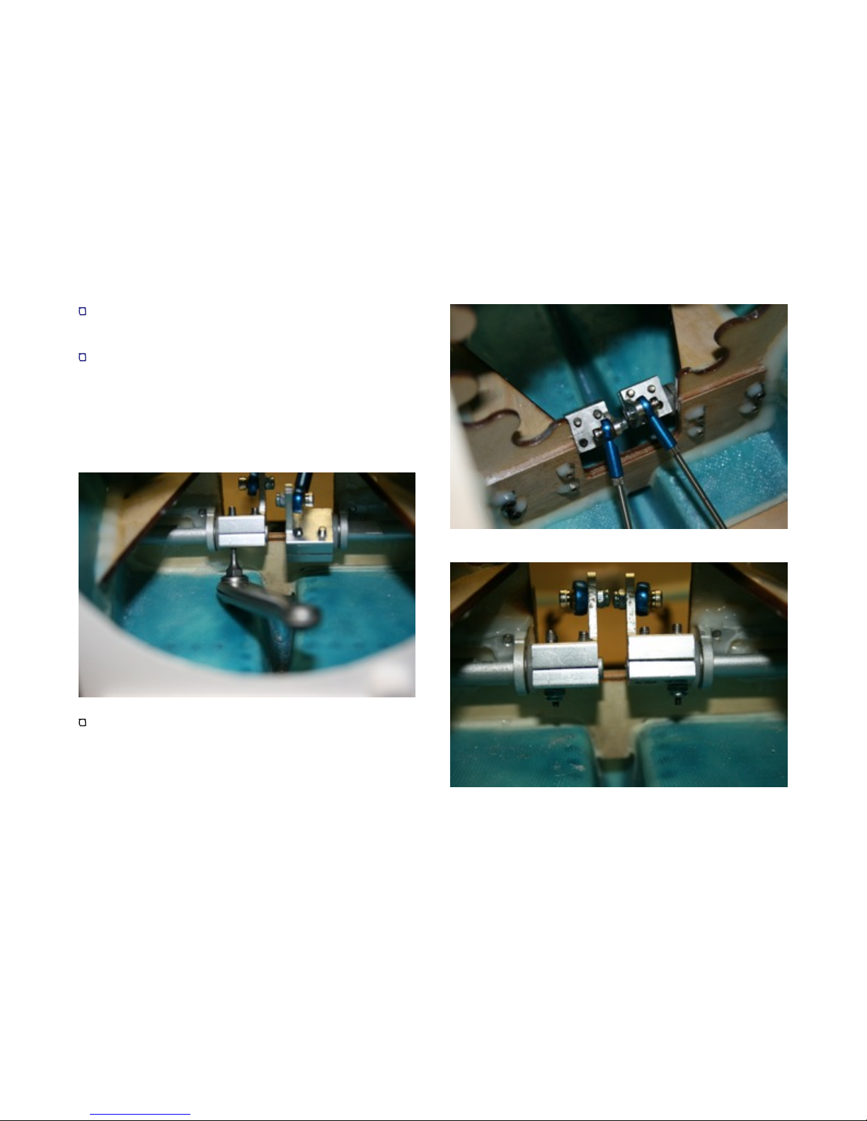
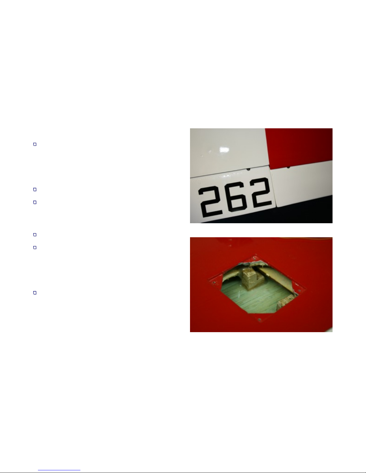
There are several ways to attach the twin stab servos
to the ply plate that is pre-installed in the fuse. FB
supplies wooden blocks with L brackets, you can buy
a commercial side mount, or make your own side
mount from ply. I elected to make my own out of ply.
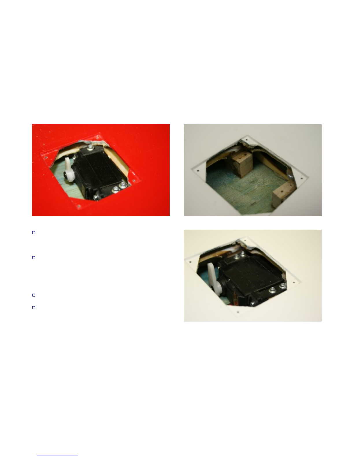
Attach your servos (8611A used here) to a
matchmaker and attach heavy duty or metal arms
such that they are approximately mirror images of
each other.
Bolt servos to mounting bracket. Do not use the
rubber grommets, as you are looking for minimal
servo movement..
Make sure your linkages are equal in length.
Working one stab at a time, attach linkage to arm,
tape stab in neutral position, set servo arm at center
point (vertical) and mount to ply plate. Make sure
linkage is line up straight between servo and horn. In
the mounting method shown here, the servo brackets
were glued to the plate with 6 minute epoxy.
Repeat for the other stab, making sure the installation
mirrors the other side.
Aft Wiring Harness
Make up your aft wiring harness, You will need
extensions for both stab servos and a rudder servo,
plus air line for speed brake open and speed brake
closed. I use nylon wrap to better protect the wires
from heat in the aft section around the pipe.
Determine length based on the placement of your
equipment. I made the harness long enough to allow
the stabs and rudder servos to be plugged in at the aft
former to allow for easier maintenance in the future.
FEI BAO T45
7
Run the harness through the top holes of the two aft
formers and affix to the side former at the aft of the
engine compartment to insure the harness will stay
clear of the pipe.
Connect air lines to the speedbrake cylinders. I
recommend you check the cylinders as you attach the
air lines to make sure they do not leak. Make sure all
air lines stay completely clear of the pipe area, and do
not interfere with the operation of the speed brake
doors.
FEI BAO T45
8
Rudder and Lower Hatch
Apply Aeropoxy carefully into the hinge point holes in
the vertical stab trailing edge. Wipe away any excess.
Put a small amount on the hinge points installed in the
rudder and insert into hinge holes. Make sure you
have enough throw for the control horn slot to just
about reach the vertical stab. This will ensure full
rudder throw. Check to make sure you haven’t left
any fingerprints and set aside to dry.
Using a small carbide cutter in a Dremel tool, enlarge
the slot in the rudder for the control horn. It may also
need to be cut a little deeper for the horn to sit down
completely in the control surface. Be extra careful not
to cut through the control surface.
Drill the control horn using a wire size drill just large
enough to allow the link bolt to fit tightly. Paint the
horn white at this time.
Rough up the gluing surface of the horn with coarse
sandpaper. Mask the area around the horn slot with
tape, fill the slot with Aeropoxy and insert the horn.
Make a nice fillet and remove the tape. Let dry.
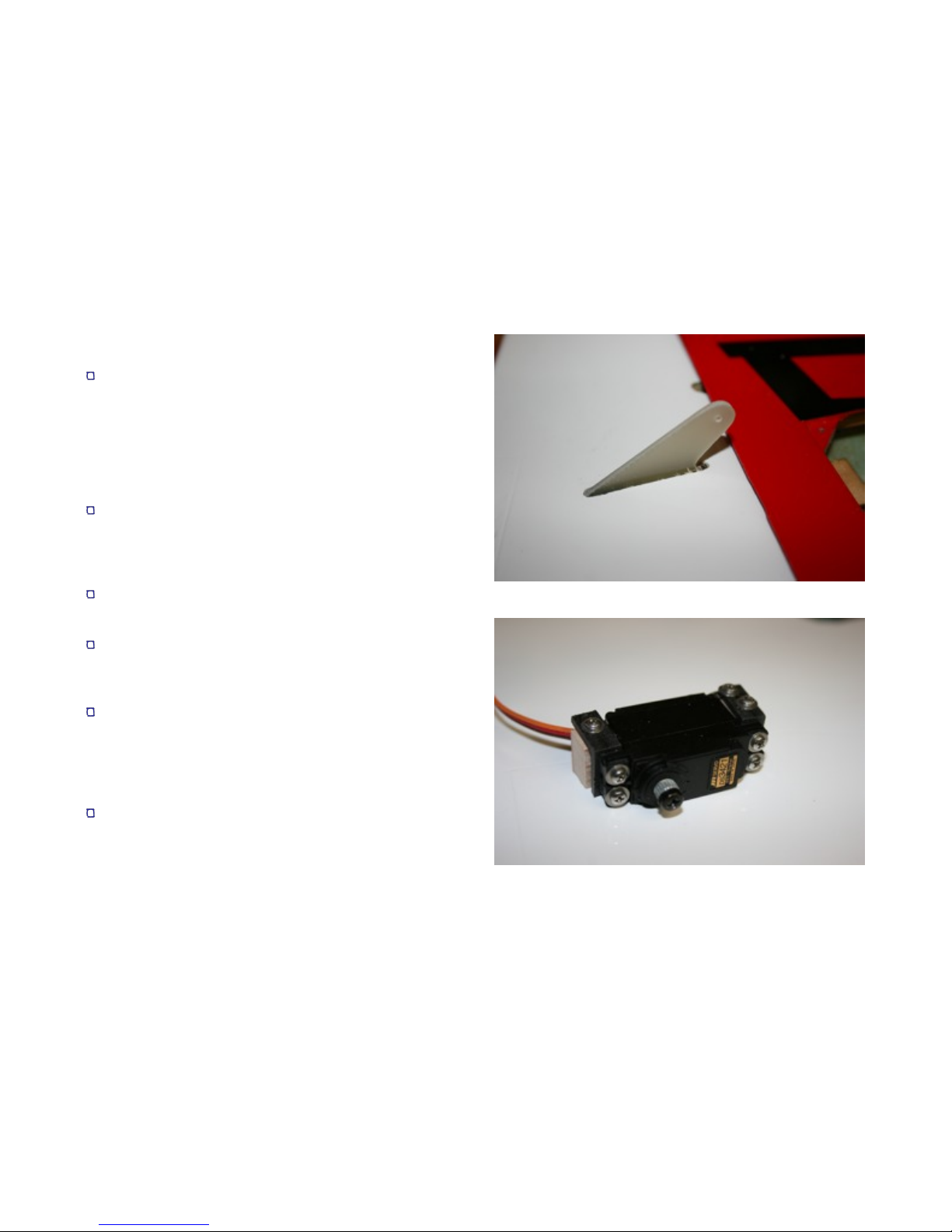
Mount the servo to wood blocks as shown, using the
aluminum mounts supplied with the kit or aftermarket
carbon fiber pieces as shown in the photo. Sand the
blocks such that they are even with the rear of the
servo, and that the servo sits as low as possible on a
flat surface.
Using a matchmaker or equivalent, find the neutral
point on the servo and attach a long single control arm
to the spindle.
FEI BAO T45
9
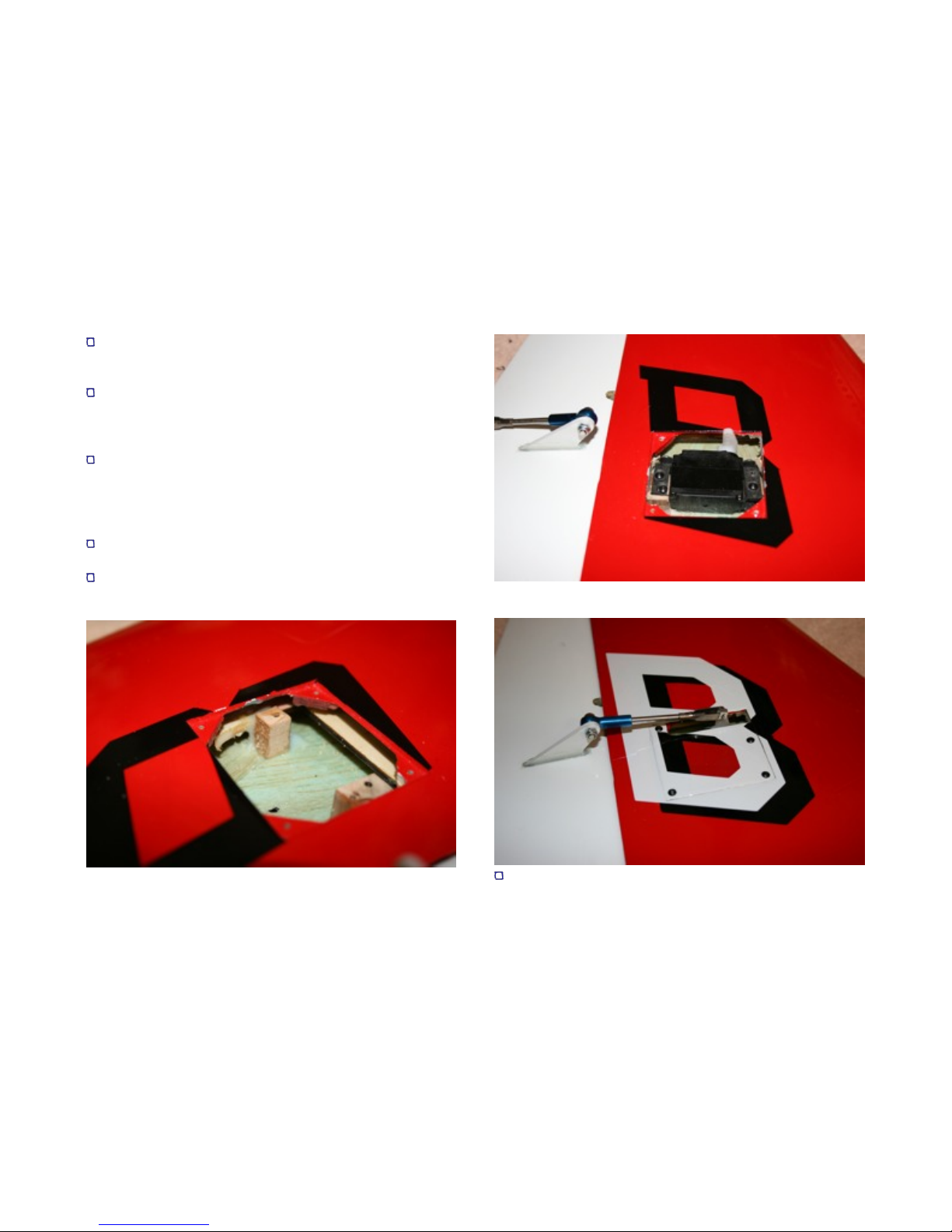
Make up the servo linkage. You will likely need to
remove the locking nuts and thread the links fully on
the rod to make it short enough. See photo.
It is important that the servo is positioned such that
the linkage is 90 degrees to the hinge line. You may
need to remove part of the mounting plate with a
cutter to allow positioning of the servo.
When you are satisfied, glue the blocks in place with
small amounts of 5 minute epoxy. Remove the servo,
and add Aeropoxy. It is important to glue the blocks to
the ply plates so the loads when the servo is actuated
are not transferred fully to the skin. See photo.
Remount servo. Note the heads may need to be
countersunk to allow the hatch to fit.
Cut a slot in the hatch cover, mount, and connect
linkage. Check for adequate throw.
Insert rudder into aft fuse. Tighten aft locking clamp.
FEI BAO T45
10

Using the large washer and cap head bolt, secure the
forward rudder spar. See photo.
Connect rudder servo to the harness and tape all
three connections. Secure wires such that they are
clear of the stab servos and will not drop into the
vicinity of the pipe when it is installed.
Locate aft ventral fin and trial fit the cap head bolt into
the pre-cut slot in the bottom of the fuse. Carefully
enlarge the slot if necessary to insure a tight slip fit.
Attach the ventral fin to the lower hatch with two cap
head screws and washers. If they don’t snug
securely, put a few drops of thin CA into the holes in
the ventral fins, allow to dry, and then reinsert the
bolts.
FEI BAO T45
11
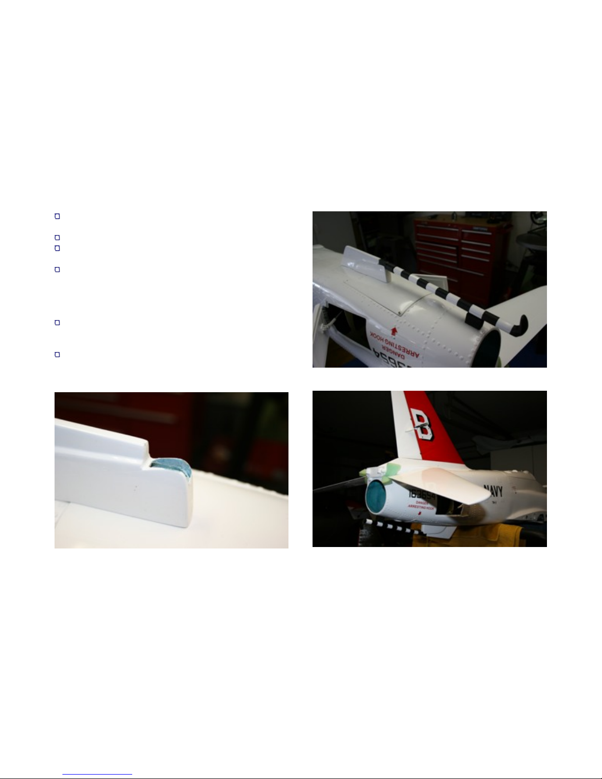
Relieve the aft part of the ventral fin for the tail hook
end. See photo.
Paint the tail hook as shown.
Make a bumper block out of scrap wood and paint it
flat black.
Glue the tail hook and the bumper block in place.
Glue the bumper block to the fuse, but not to the hook.
Drill a couple of small holes in the area the bumper
block will be glued to the fuse to allow small “buttons”
of glue to strengthen the joint.
Drill a small hole through the tail hook into the bumper
block and attach with a long screw. Use thin CA to
harden the thread area in the block.
This completes the aft fuse construction. As an
option, after market vinyl graphics were applied to
dress up the rudder.
FEI BAO T45
12

Fuel System
You can choose to install the smaller tank flat on top of
the larger tank, or if you wish to leave more room
above the engine for a smoke tank, follow the
installation procedure outlined below. Details for
smoke tank installation are at the end of the manual.
Optional: disassemble the stopper assemblies from
the tanks and inspect for kinks, tube constriction from
the cutting process or burrs at the ends of the copper
tubes. If you want to move to 3/16 inch tubes, drill the
steel stopper plates at this time. You may wish to
replace the pickup tubing supplied with high quality
large Tygon. Wire tie all internal connections.
Leak check both tanks.
Cut a piece of hard foam to sit under the main tank.
FEI BAO T45
13

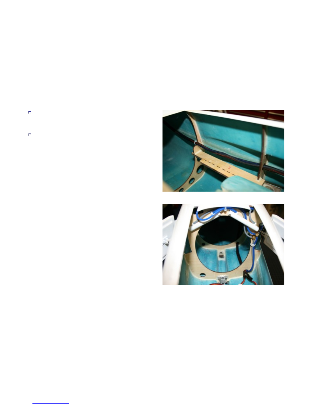
Install smaller tank in front of large tank (see photo).
Fuel should flow from the large tank to the smaller
tank and then to the air trap or pump.
Cut a piece of scrap ply approximately 1/2 inch by 6
3/8 inch. Bolt in place to the formers at the top of the
small tank to keep it from moving upwards in flight.
Remove tanks, and re-plumb lines if necessary.
Reinstall tanks and hold down ply. Drill a hole in the
lower right side for the vent fitting (not supplied) and
connect line.
Using wire tie as shown, clamp small tank to ply hold
down to keep it from shifting forward in flight.
Now would be a good time to fill the system and check
one last time for leaks. When completed, plug the
lines to keep the kero from leaking as you finish work
on the airframe.
FEI BAO T45
14
Wings
Begin construction on the wing by gluing the flap and
aileron hinges into the predrilled holes in the root edge
of the wing. Before gluing, insure that you are able to
achieve necessary throws, there is adequate
separation between flap and aileron, and that the aft
edges align. Use Aeropoxy to provide adequate time
to align and tape the parts in place.
Using a Matchmaker or receiver, center the aileron
servos and attach servo arms in mirroring positions.
Mount the servos to the aluminum L brackets.
Optional: as the brackets may need to be trimmed,
you may choose to substitute carbon fiber pieces for
the aluminum brackets supplied with the kit. These
may be easier to work with.
Remove the servo hatches, marking them for location
and orientation as you do.
Trim and position the wooden mounting blocks into the
servo pockets such that the servo arms are aligned
with the slots for the servo horns. Allow for the offset
of the ball ends. You may need to trim back the
mounting plates pre-installed in the wings to achieve
alignment. The servos are all positioned such that the
servo arm is toward the front of the wing.
When satisfied, put a drop of thick CA on the bottom
of the blocks and position in the wing. When dry,
remove the servos and use Aeropoxy to permanently
affix the blocks. Tie the servo mounting blocks into
the former structure with glue to prevent the upper
wing surface from flexing under load.
FEI BAO T45
15
When the aileron servos have been fitted, repeat
steps for the flap servos. You may wish to back up the
flap mounting blocks with scrap balsa blocks to
provide added security for the larger servos.
Add servo extensions to the aileron servos. The wires
will exit the wing at the aft hole just in front of the anti-
rotation pin. You will find it easier to fish the servo
wires through the wing if you attach a string to a large
nut and drop it down through the rib holes. Tape the
servo wire to the string and pull it through the wing.
If using 8611A servos on the flaps, the wires should be
long enough without the use of extensions.
Reinstall the servos into the wing pockets and test
with a receiver or Matchbox to make sure you have
adequate clearance for the servo arms. Trim as
necessary.
FEI BAO T45
16

As you did for the rudder servo horn, carefully route
out the mounting slot so the horns sit down fully into
the control surface.
Enlarge the hole in the phenolic control arm horns for
the ball link bolt at this time. Find the wire size drill
that is the tightest fit possible to avoid slop.
Paint the horns if desired.
Rough up the gluing surface on the horns.
Tape around the horn slots in the control surface.
Glue the horns in place using a sufficient amount of
Aeropoxy. Make a nice fillet, and remove the tape.
Insure that the horns are kept in a vertical position as
the glue dries.
When the glue has dried, fit the linkages. The two
shorter linkages are for the Ailerons, the two longer
linkages are for the flaps. To allow for the linkage
cover to fit, the ball link must be attached to the
control surface horn.
Make sure when fitting the linkages that the servo
output arms for both ailerons and both flaps are in
identical positions to avoid uneven movement.
For each servo, mark and cut slots in the servo hatch
cover for the linkage and servo arm.
Cut the aft end off the linkage covers. Position them
on the hatch such that they just clear the ball link
attached to the control surface in their lowest position.
Mark the edges of the linkage cover on the hatch.
Carefully grind away the paint just inside these lines,
to provide a good gluing surface (see photo).
Position the covers into place and lightly CA them to
the hatch only. When dry, remove the covers and
reinforce the joint from the inside with Aeropoxy.
Reinstall hatch covers.
FEI BAO T45
17
Engine and Pipe
It is highly recommended that you use at least the
lower bypass in the installation. The gear doors are
cut into the fuselage just in front of the engine intake
and a significant amount of debris might easily be
pulled into the engine intake if not protected.
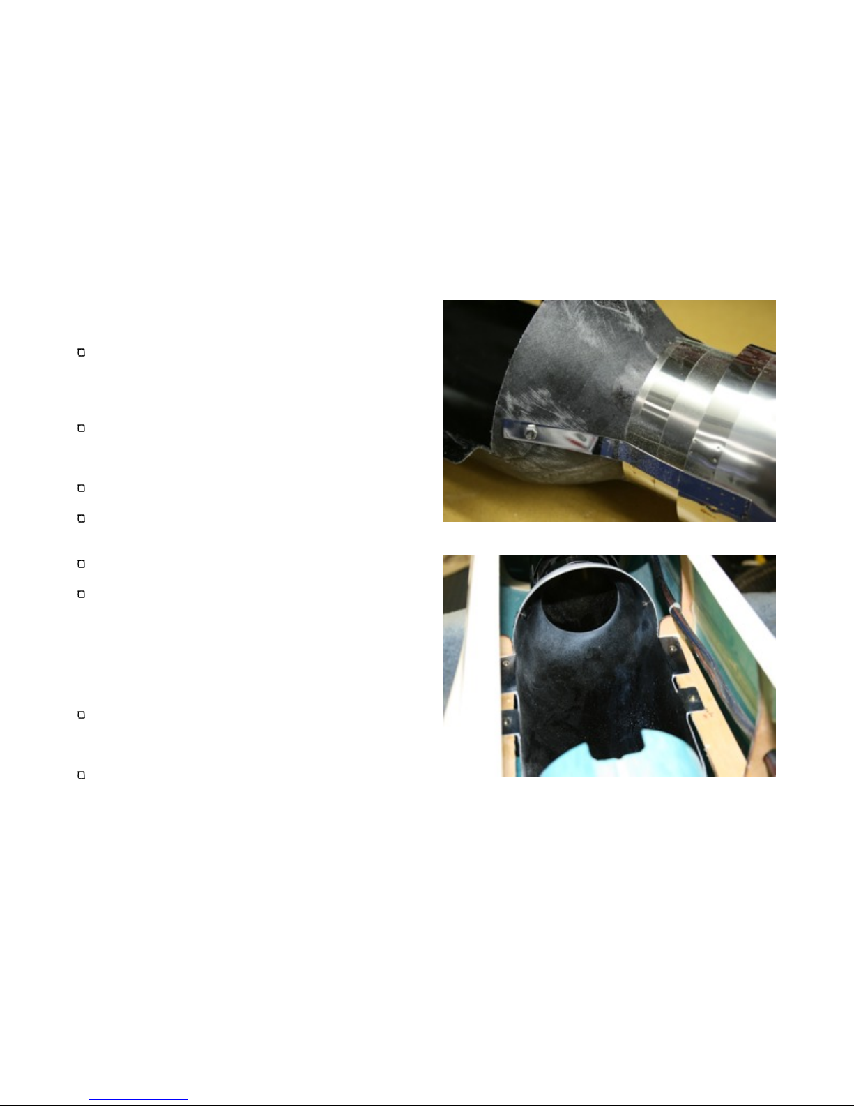
Fit the pipe to the rear of the bypass. Note that the
tabs on the pipe are not exactly centered. Position the
pipe so the tabs are oriented toward the top of the
bypass.
Straighten the tabs to remove any folds. The tabs
should be relatively straight.
Make sure the pipe is fully positioned up onto the
bypass. Drill holes through the tabs and the bypass
and fit bolts. Do not tighten at this point.
Remove the pipe and paint the exhaust end with flat
black paint if desired.
Trial fit the pipe, the bypass and your engine into the
fuse. The fixed intakes may require trimming to allow
forward clearance for larger engines. The intakes
may also need to be notched at the top to allow
clearance for the starter assembly. Position the
bypass such that the engine is as far forward as
practical, while allowing the pipe to protrude slightly
from the aft of the fuselage.
Make sure the engine is centered in the bypass to the
pipe, and that you allow the appropriate separation
between the exhaust cone and pipe as specified by
the engine manufacturer.
If necessary, trim the bypass to allow the engine tabs
to sit flat on the mounting rails (see photo).
FEI BAO T45
18

Remove the engine temporarily and fix the bypass to
the mounting rails with wood screws.
Reattach the pipe to the aft of the bypass and secure
with bolts. If desired, a drop of thin CA can be used to
insure the nuts do not loosen.
Check the pipe where it passes through the aft former
for any play. If there is a lot of play and the pipe
moves freely about, cut additional supports out of
scrap wood and glue them to the aft former. Allow just
a little play so the band around the aft of the exhaust
pipe will fit through in the event it must be removed.
Insure that the wiring and speed brake lines are
secured well away from the pipe.
Completely clean the intakes, bypass and aft area of
the model with a vacuum or compressed air.
Reinstall your engine, securing it to the mounting rails
with wood screws or cap screws with blind nuts.
Check again to make sure it is centered and that the
angle of the engine matches the angle of the pipe.
Use washers under the mounting tabs if necessary to
achieve the proper alignment.
If you elect to use the upper bypass, trim, fit and
secure to the engine rails using wood screws.
The photo on the right shows a Jet Central Super
Eagle/Rhino installation. Wooden plates were used to
widen the mounting tabs to sit on the rails. Note the
smoke system tubes secured to the tops of these
mounting tabs.
FEI BAO T45
19

Component Boards
At this time, lay out your electrical, air and engine
systems on the component boards in the cockpit
area. Make sure to allow adequate clearance for
the cockpit tubs.
Remember to make all your components accessible
for maintenance. While it may look extra neat to
hide everything away, things do break and leak, and
you want to keep your repair time to a minimum.
Run air lines to all cylinders and gears. You will
need to plan for a three sequence installation, gear
and two different door cycles. The main gear doors
and forward nose gear doors close after gear
extension while the two doors that flank the nose
strut remain open. A UP2/4 valve combination or
one of the growing number of gear sequencers will
be required.
Nose Gear Steering
Install a control arm on the nose gear servo. Make
sure it is centered using a Matchmaker or receiver.
Note the orientation is along the axis of the servo,
not perpendicular as is normally the case.
Install your nose gear servo into the mount pre-
installed at the forward end of the nose
compartment.
Run steering cables to the nose gear. A nylon wire
tie may be attached to the cables with heat shrink to
act as a spreader when the gear retracts.
Make sure the steering cable is not too tight with the
gear extended to prevent binding on retraction.
FEI BAO T45
20
Other Fei Bao Toy manuals

Fei Bao
Fei Bao F-4 Phantom II User manual

Fei Bao
Fei Bao hawker hunter User manual

Fei Bao
Fei Bao F-9F Panther User manual

Fei Bao
Fei Bao SU-27 User manual

Fei Bao
Fei Bao Mirage F1 User manual

Fei Bao
Fei Bao EF2000 User manual

Fei Bao
Fei Bao Mirage 2000 User manual

Fei Bao
Fei Bao MB-339 User manual

Fei Bao
Fei Bao MiG-21 Fishbed User manual

Fei Bao
Fei Bao F18-f User manual


Popular Toy manuals by other brands


Eduard
Eduard Zoom Mosquito FB Mk.VI/NF Mk.II quick start guide

Sportsman Aviation
Sportsman Aviation POLECAT RACER .40 Building instructions

marklin
marklin 37359 user manual

Rail King
Rail King 30-2274-0 Operator's manual

Klein
Klein MIELE 6941 instructions

Hasbro
Hasbro Star Wars Revenge of the Sith Energy Blaster refill... instruction manual