Fei Bao Velox XL User manual

F E I B A O V E L O X X L
1
FEI BAO JETS
Velox XL Assembly Manual
Written by Curtis Mattiko
In collaboration ith R/C Jet Models

F E I B A O V E L O X X L
2
DISCLAIMER:
THIS IS NOT A TOY. This is a high-performance miniature aircraft, capable of high speeds and
damage to life, limb, and property. The manufacturer and its distributors cannot control how you
assemble this model, what equipment you use to fit it out, or how you fly it, and can assume no liability
whatsoever for any damages that may occur when you fly your aircraft. By assembling this model, you
are agreeing to indemnify and hold blameless the manufacturer and/or his agents from any and all torts
and liability associated with the use of this product. Please inspect all parts before beginning assembly.
If any parts appear to be suspect, contact your dealer or the manufacturer for repair or replacement
B FOR you begin. Once you have assembled the aircraft, you are the pilot in command and assume
any and all responsibility for the use of the model and any damages that might occur by flying or
attempting to fly this aircraft.
R/C model jets require a high level of skill in both their assembly and their flying. If you do not feel
confident in either your building or flying skills, PL AS seek assistance from more experienced
modelers. It is a wise idea, no matter what level of skills you possess, to have a second experienced
modeler go over your installation after assembly. A second set of eyes may spot a problem you have
missed. If you have not flown a model like this before, it is HIGHLY recommended that you get an
experienced turbine pilot to do your maiden flight. Very often, the first few seconds of a maiden flight
are critical until the aircraft is trimmed out, and having an experienced pilot at the controls can make the
difference between a wrecked aircraft and once that enjoys many hundreds of flights. Be sure to select a
suitable field for flying...take the time to find a large paved runway if at all possible, especially for test
flights, until you feel comfortable getting the aircraft in and out of smaller grass fields.
BEFORE YOU BEGIN:
Keep this in mind as you proceed:
Look at V RY assembly step you finish, and ask yourself:
"Is this going to crash my airplane?"
A chain is only as strong as its weakest link, and this is a high-performance aircraft that will be very
intolerant of sloppy assembly techniques. ven the smallest component is important and can cause the
loss of your airplane, so take the time to do things right. Or R do them if they are wrong. Careful work
will result in a long-lasting plane that gives you years of pleasure, one loose component could result in
the complete loss of the aircraft and all the components inside it, and someone can even get hurt. So
pause every once in a while when building it and double-check your workmanship.
A. Introduction:
You have chosen a model that represents the pinnacle of ARF technology. While there is not a lot of
building to do, there is enough to keep you busy for a few evenings.
ven if you have assembled maybe other ARF jets, we highly recommend following our assembly
sequence and procedures anyway.
Chances are it will save you a lot of time, prevent you from running down dead ends, and perhaps

F E I B A O V E L O X X L
3
remind you of a few small things that might end up saving your aircraft.
We have tried to arrange a construction sequence that will allow you to keep moving forward, rather than
standing around waiting for glue to dry before you can proceed to the next step.
Just because the model is almost completely built does not mean you can rush through the final
assembly.
You need to employ fine craftsmanship every step of the way, turbine models are critical. Keep this in
mind with everything you do, every part you install...look at the work you just did, evaluate it critically,
and ask yourself "is this going to potentially crash my airplane?" If there is any doubt about the work
you have done, back up, and re-do it properly.
B. Adhesives:
The correct adhesive to use for all procedures is Loctite Hysol 9462. This is a very strong white epoxy
that is thixotropic. "Thixotropic" means it does not run at all, but stays only where you put it. It is
infinitely superior to regular epoxy, even slow-setting epoxy, for our purposes, because of this
characteristic.
Regular epoxy will run downhill with gravity as it dries, taking it away from where it is supposed to be.
A good example is in the hinges...using regular epoxy, a good portion of the glue will migrate down away
from the hinge into the inside of the wing as it dries, and you won't even know it is happening. Hysol
stays where you put it.
The downside of Hysol is it takes overnight to dry properly, but we have tried to arrange things to keep
you busy while waiting for glue to dry.
We also highly recommend that you only use a proper Hysol dispensing gun, and only the long-type
mixing nozzles.
The short nozzles do not mix this glue enough, and only a thin nozzle and gun will let you fill the hinge
and control horn holes properly with glue, you can't do it mixing your Hysol on a flat surface and trying
to get the glue in the proper place by a brush or stick.
You can buy a complete Hysol setup with a gun, nozzles, and two cartridges of glue from your dealer for
approximately $60.
Consider it a great investment, the glue is the best you will use. One cartridge is plenty to assemble your
Velox.
C. WORKING WITH PNEUMATIC SYSTEMS:
The Velox XL uses pneumatic brakes and retracts. If you follow a few tips, you should have very
reliable, leak-free operation. Neatness counts.
All airlines should be secured to the airframe to keep them from flopping around or getting kinked. Use
tie wraps for this.
The other very important thing is to cut off the end of each airline dead square before installing it on the
nipple.
This is VITAL. You can either purchase a professional tubing cutter from your dealer (they are
approximately $10), or you can make up a little jig to hold the airline and keep a sharp, new razor blade
perfectly upright as you cut.

F E I B A O V E L O X X L
4
ither one works, just ensure that all ends of all airlines are cut off dead square. Make sure all airlines are
pushed ALL TH WAY onto their nipples.
They should not need to be secured otherwise, but you can add fine wire safety wraps if you like. Make
sure all left and right matching airlines are the same length, particularly the brake lines, or you will get
uneven retraction or braking action.
It's worth taking the time to get everything pneumatic right the first time, as having your landing gear fail
to retract is not THAT bad, but having it fail to deploy can really ruin you day and the paint on the
bottom of your model.

F E I B A O V E L O X X L
5
1. Using a sharp knife, trim off the ends of the white nose
gear steering tubes, to clear the radio tray so you can
remove it.
Figure 1
2. Remove the two screws holding the radio tray in and
remove the tray.
Figure 2
3. Sand and paint the tray if you like and set it
aside to dry.
Figure 3
4. Cut the tie-wrap holding the nose gear in place for
transportation.
Figure 4
5. Add airline to the rear nipple of the nose gear.
Figure 5
6. Using hemostats add tubing to the side nipple of the
nose gear and route as shown. It greatly helps to
color-code your airlines.
Figure 6

F E I B A O V E L O X X L
6
7. Cut off these tubes, leaving about six inches of slack in
the radio compartment, and add a y connector to each.
Tape them to the floor out of the way.
Figure 7
8. Note that if you are using a sequencing valve that has
two outputs for each function that you will not need y-
connectors to connect the front and rear retracts.
Figure 8
9. Add two sections of airline to the nose gear door
cylinder and add y-connectors. Again, y connectors not
needed with valves that have dual outputs.
Figure 9
10. Remove the bolt holding the forward main gear door
cylinder to the door hinge. This will let you swing the
cylinder out and access the nipples on it.
Figure 10
11. Make up an airline harness consisting of two four inch
pieces of tubing, a y connector, and another length
about 30 inches long.
Figure 11
12. Use this to connect the upper nipples of the two main
gear door cylinders.
Figure 12
13. Swing the cylinder back into place and replace the
bolt holding it to the hinge.
Figure 13
14. Make up another airline harness like the first one.
Figure 14

F E I B A O V E L O X X L
7
15. Connect the two lower nipples on the door cylinders
with this new harness.
Figure 15
16. Run the lines from the rear door cylinders forward
through the middle of the fuse and connect them to the
front cylinder y connectors as shown.
Figure 16
17. Use your hand pump to extend both main retracts.
Check and tighten all bolts with the provided wrenches.
Figure 17
18. Add lengths of airline to the retracts. The ones to the
outer nipples need to be 20 inches long, the side
nipples 12 inches long.
Figure 18
19. Slip the retracts into place and secure with screws.
Be sure to not pinch the airlines.
Figure 19
20. Connect the lines from the retracts with y connectors
and run line forward to the nose like you did for the
door cylinders.
Figure 20
21. Connect these lines to the nose gear lines, unless
you are using a valve that provides dual outputs for
nose and main gears.
Figure 21
22. Secure the airlines to the retract frames with a tie
wrap on each retract. Be sure not to pinch or kink the
lines.
Figure 22

F E I B A O V E L O X X L
8
23. Open the struts with the doors attached (mains)
Figure 23
24. Add two 16-inch lengths of airline to the brakes and
secure to the struts as shown.
Figure 24
25. Connect the two brake lines together with a y connector
and run a line forward from there to the nose.
Figure 25
26. Tape the brake line out of the way to the fuselage floor
for now.
Figure 26
27. Bundle the lines in the wheel wells together for
neatness using tie wraps.
Figure 27
28. Add five tie wraps around the bundle of lines going
from the wheel wells to the nose.
Figure 28
29. Slide those tie wraps down the bundle to leave an
even spacing between them as shown.
Figure 29
30. Connect the two air bottles together using 16 inch
lengths of line and a y connector, then add another
12 inches to the y connector.
Figure 30

F E I B A O V E L O X X L
9
31. Glue the air bottles into the fuselage using silicone or
epoxy.
Figure 31
32. Second air bottle on the right side of the fuselage.
Figure 32
33. Locate all the tank parts. Check the holes in the tanks
and open if needed to fit the stoppers. Also blow out the
insides of the tanks completely clean of all dust.
Figure 33
34. Clean up the end of each tube if needed, blow out any
dust or shavings.
Figure 34
35. Assemble the stoppers as shown.
Figure 35
36. Add the clunks and lines, secure each end with a tie
wrap.
Figure 36
37. Bend up the vent tubes on all three stoppers.
Figure 37
38. Install the stoppers in the tanks. Be sure to mark
which lines is fuel and which are vent. Pressure tests
each tank for leaks in a bucket of water or a sink.
Figure 38

F E I B A O V E L O X X L
10
39. Install the two saddle tanks. You will need to turn and
rotate them to get them through the center opening in
the main former.
Figure 39
40. Put silicone glue under and in front of the tanks to
secure them.
Figure 40
41. These included ply plates are also for securing the
tanks.
Figure 41
42. Put the plates into place and secure with a little CA
glue.
Figure 42
43. Insert the main tank and fix it in place.
Figure 43
44. Prepare the control horns by roughening the bottom
ends as shown for better gluing.
Figure 44
45. Drill out the hole in each horn to match the bolts on
the provided links.
Figure 45
46. Mark each servo cover on the elevator, wings, and
rudder. Keep the covers oriented. Remove them and
put them aside.
Figure 46

F E I B A O V E L O X X L
11
47. Add a pair of servo mounts to one servo, and a link to
one horn. This will be a dummy rig to establish the
location of each control horn.
Figure 47
48. Use your rig, a ruler, and a marker to locate and mark
where each horn will go. Be aware of the servo horn,
and allow for the offset of the ball link.
Figure 48
49. Cut a slot for each horn using a sharp exacto. It does a
neater job than power tools for this, and only takes a
few minutes.
Figure 49
50. Box each slow in with tape as shown.
Figure 50
51. Coat the bottom of each horn with hysol. Make sure
the holes are filled with glue.
Figure 51
52. Fill the slots with hysol also. then fair the horns in with
a small fillet of glue.
Figure 52
53. Smooth the fillet with your finger, then remove the
tape and you will have a neat job.
Figure 53
54. You may use tape to make sure the horns remain
upright while drying. Put all these surfaces aside to
dry overnight.
Figure 54

F E I B A O V E L O X X L
12
55. When the hysol is dry, you can paint the horns and
fillets to match your airframe for better appearance.
Figure 55
56. By now, the silicone holding the tanks should be dry,
let's get back to the fuel system. Make up a tygon
harness to link the outer tanks to the center one.
Figure 56
57. Use this to connect the fuel outlets of the outer tanks to
the vent of the center tank. Keep the tubing lengths to
the outer tanks identical.
Figure 57
58. Make up another y harness as shown. Leave the third
line long, it will need to reach forward and function as
an overflow when you fill your tanks.
Figure 58
59. Use this harness to connect the vents of the outer
tanks, and then tape the overflow line out of the way
forward.
Figure 59
60. Now add a length of tygon to the fuel outlet of the
main tank. Leave this one long enough to reach to
your UAT, which will be mounted forward.
Figure 60
61. Secure all lines with tie wraps. You may find it easier
to partially tighten the tie wrap on the line further out,
then slide the tie wrap down the line to the tank and
tighten.
Figure 61
62. Install your sequencing valve and servo and linkage
to a scrap plywood mount. The UP3 valve is shown,
but others such as the Jettronics or other sequencing
solutions are fine.
Figure 62

F E I B A O V E L O X X L
13
63. Use velcro to install the valve on the fuselage floor.
Check clearance with the radio tray and other
components. Plumb the valve according to the
manufacturer's instructions.
Figure 63
64. Mount the brake valve and a servo to a scrap plywood
mount.
Figure 64
65. Note the use of a plywood block to space the valve
upwards to keep side loads off the valve spool. Also
note the use of the innermost hole on the servo to get
the most accuracy.
Figure 65
66. Install the brake valve assembly with velcro also.
Connect the line to the brakes to the outer port of the
valve (shown with clear line) and add a section of line to
the other port.
Figure 66
67. Use that section of line and a y connector to connect
the inputs of both the brake and sequencing valves.
Figure 67
68. Connect that to the y connector connecting the two
air tanks using a short section of line.
Figure 68
69. Bisect that line, add a y connector, and add a 14 inch
length of line to that.
Figure 69
70. Connect that line to your air filler valve. Fill and test
your systems. Shorten and neaten and secure all
airlines.
Figure 70

F E I B A O V E L O X X L
14
71. Attach a wheel collar to a 36-inch piece of string.
Figure 71
72. Tie the loose end of the string to a 36 inch heavy duty
extension.
Figure 72
73. Use electrical tape to fair the string into the connector.
Figure 73
74. Use gravity to dangle the wheel collar and string
through the boom at the holes shown.
Figure 74
75. Gently pull the extension through using the string.
Figure 75
76. Tape the extensions out of the way, and be sure to
mark both ends of the extensions with the
corresponding surface numbers from earlier.
Figure 76
77. Put a second extension through for the rudder servo.
Figure 77
78. Again, labeling the extensions will save you a lot of
headache later.
Figure 78

F E I B A O V E L O X X L
15
79. Repeat the process for the other boom. Note that the
extensions must emerge on the inboard side of both
booms.
Figure 79
80. Mark four 36-inch extensions with numbers at both
ends corresponding to the appropriate servos for one
side of the aircraft.
Figure 80
81. Neatly secure these four extensions together using tie
wraps every six inches.
Figure 81
82. Feed this bundle into the aircraft as follows in through
the hole shown in the wing root.
Figure 82
83. Through the hole in the former behind the main gear
as shown.
Figure 83
84. Through the former in front of the main gear as
shown, keeping the extensions above and away from
the airlines.
Figure 84
85. and into the forward fuselage as shown, keeping the
bundle below all the air and fuel lines. Repeat this
process with four extensions for the other side of the
aircraft.
Figure 85
86. Install the metal mounts on the servo. Do not use
servo grommets. Make sure the screws are long
enough to thread well into the mounts.
Figure 86

F E I B A O V E L O X X L
16
87. Center the servo and add the horn. Be sure to size the
holes in the horn for the provided Fei Bao clevises.
Figure 87
88. Tie a wheel collar to a string, and tie the string to the
servo lead.
Figure 88
89. Drop the wheel collar and string through the structure
and out the hole for the servo lead.
Figure 89
90. Pull the servo lead through and seat the servo on the
wooden mounts in the structure. Check the wooden
mounts for security, reglue if needed.
Figure 90
91. Label the servo lead with the appropriate number.
Figure 91
92. Drill pilot holes for the servo mounting screws.
Figure 92
93. Use four kit provided self-tapping screws to secure
the servo into place.
Figure 93
94. Put the properly numbered servo cover into place.
Mark and cut a slot in the edge of the cover for the
servo horn.
Figure 94

F E I B A O V E L O X X L
17
95. Screw the servo cover into place.
Figure 95
96. Find the control linkage closest in length and measure it
against the needed distance between the centered
control horn and centered servo horn.
Figure 96
97. To shorten any linkage, leave the locknut in place,
remove the clevis or ball link, and touch the threaded
rod against a power sander. Bevel the shortened edge,
and then unscrew the locknut to clean the threads.
Figure 97
98. Bolt the link into place. Tighten fully, and then loosen
only until you get free movement.
Figure 98
99. Connect the clevis at the other end, and secure it with
the provided safety clip.
Figure 99
100. All the other servos install similarly. Be sure to
tape any extensions for safety. The aileron servos
will require 12-inch servo extensions to reach to the
wing root rib openings.
Figure 100
101. Add a nose gear steering servo to your radio
tray.
Figure 101
102. Add radio switches to the tray.
Figure 102

F E I B A O V E L O X X L
18
103. Install your UAT to the tray using tie wraps as
shown.
Figure 103
104. Fit the tray into the fuse. Note all servo leads are
run to the top of the tray, and that the air fill valve goes
through the hole as shown and gets it's locknut on the
top of the tray.
Figure 104
105. Plumb the feed line from the main center tank to
the input of your UAT.
Figure 105
106. Add a fill line to the correct port of your UAT and
plug it with the provided fuel plug.
Figure 106
107. Test fit your engine to the mounts. Get it as far
forward as possible for balance, modify the mounts if
needed.
Figure 107
108. Mark around the starter motor where it hits the
forward end of the engine bay.
Figure 108
109. Mark a circle at the correct spot big enough for
the starter bullet to go through with ample clearance.
Figure 109
110. Cut the marked hole and check the fit of the
starter though the hole.
Figure 110

F E I B A O V E L O X X L
19
111. Slit some airline tubing and CA it around the
edges of the hole to give it a smooth edge.
Figure 111
112. Slide the engine into place and mark as required
for holes for fuel, gas, and electrical lines.
Figure 112
113. Cut these holes and line them with slit airline or
rubber grommets to keep the lines from being abraded.
Figure 113
114. Carefully align the engine and mark the mounting
holes.
Figure 114
115. Drill pilot holes for the engine mounting screws.
Be sure not to drill too far and come out the bottom of
the fuselage.
Figure 115
116. Mount the engine using screws and washers.
Vacuum the engine bay carefully to remove any
debris.
Figure 116
117. There are many options for setting up your
electronics. The best way is to make a second tray to
go behind the cockpit.
Figure 117
118. Make up a plywood tray as shown, approx.
125mm deep, 180mm at the rear edge, and 155 at
the front. Test fit it into the fuse.

F E I B A O V E L O X X L
20
Figure 118
119. Plan how you want to install your ECU, solenoids,
and fuel shut off on this tray. Be aware of the need to
plug your data terminal in, and the need to get to the
manual shutoff valve.
Figure 119
120. Make up mounts as required, and holes for fuel
lines and wires.
Figure 120
121. Put a small plywood block at each forward bottom
corner to mount the tray. The center ply block is a
mount for the fuel shut off.
Figure 121
122. Sand the tray and paint it.
Figure 122
123. Plumb and wire the equipment according to
your engine manual. Note you may need lines long
enough to reach the engine in the rear of the model.
Figure 123
124. Install the tray with two screws as shown. You
may want to glue two small blocks to the former to
support the rear of the tray. Connect the engine
electrical to the ECU.
Figure 124
125. Install your fuel pump and connect it to the
UAT.
Figure 125
126. Run the fuel and gas lines into the engine.
Figure 126
Table of contents
Other Fei Bao Toy manuals
Fei Bao
Fei Bao F-9F Panther User manual
Fei Bao
Fei Bao T45 User manual

Fei Bao
Fei Bao EF2000 User manual
Fei Bao
Fei Bao MB-339 User manual
Fei Bao
Fei Bao SU-27 User manual

Fei Bao
Fei Bao F-4 Phantom II User manual
Fei Bao
Fei Bao L-39 User manual
Fei Bao
Fei Bao hawker hunter User manual
Fei Bao
Fei Bao Mirage 2000 User manual
Fei Bao
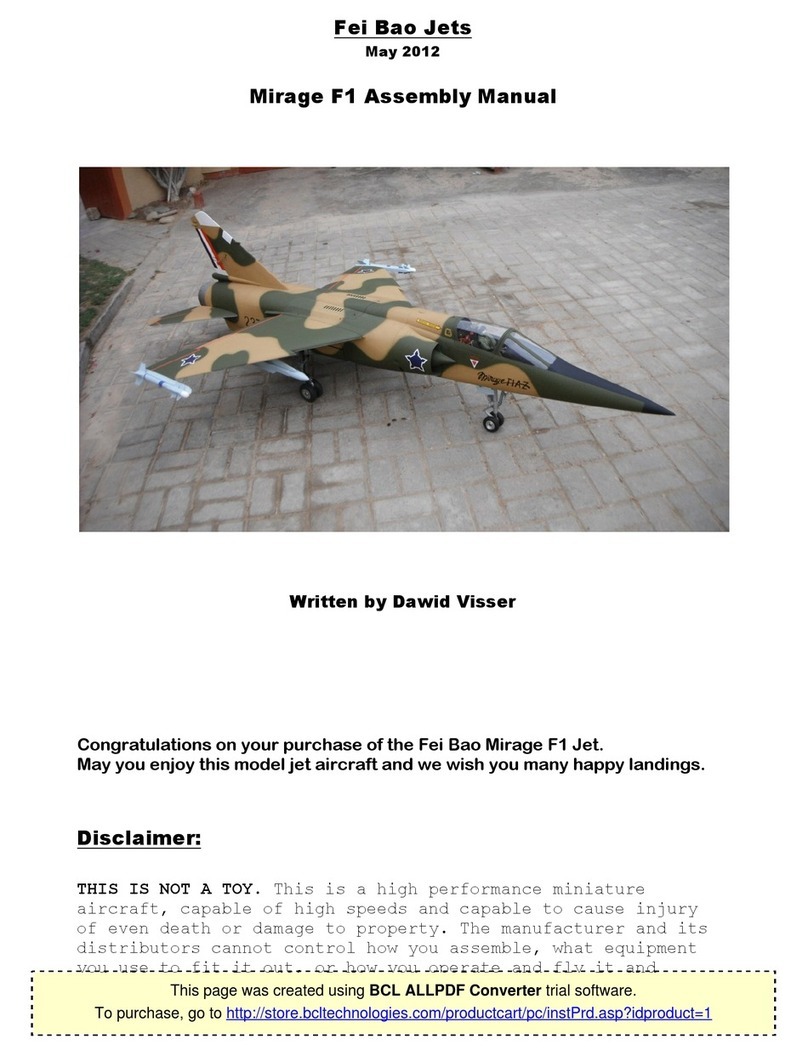
Fei Bao Mirage F1 User manual
