Fei Bao Mirage 2000 User manual
FEI BAO Mirage 2000 Apr 14
1
FEI BAO
Written by Peter Love
Thanks to Richard Spreadbury for his build tips and reference photos.
MIRAGE 2000
ASSEMBLY MANUAL
APRIL 2014

FEI BAO Mirage 2000 Apr 14
DISCLAIMER
THIS IS NOT A TOY. This is a high-performance miniature aircraft, capable of high
speeds and damage to life, limb, and property. The manufacturer and its distributors
cannot control how you assemble this model, what equipment you use to fit it out, or
how you fly it, and can assume no liability whatsoever for any damages that may
occur when you fly your aircraft. By assembling this model, you are agreeing to
indemnify and hold blameless the manufacturer and/or his agents from any and all
torts and liability associated with the use of this product.
Please inspect all parts before beginning assembly. If any parts appear to be suspect,
contact your dealer or the manufacturer for repair or replacement BEFORE you begin.
Once you have assembled the aircraft, you are the pilot in command and assume any
and all responsibility for the use of the model and any damages that might occur by
flying or attempting to fly this aircraft. R/C model jets require a high level of skill in
both their assembly and their flying. If you do not feel confident in either your
building or flying skills, PLEASE seek assistance from more experienced modellers.
It is a wise idea, no matter what level of skills you possess, to have a second
experienced modeller go over your installation after assembly. A second set of eyes
may spot a problem you have missed. If you have not flown a model like this before,
it is HIGHLY recommended that you get an experienced turbine pilot to do your
maiden flight. Very often, the first few seconds of a maiden flight are critical until the
aircraft is trimmed out, and having an experienced pilot at the controls can make the
difference between a wrecked aircraft and once that enjoys many hundreds of flights.
Be sure to select a suitable field for flying...take the time to find a large paved runway
if at all possible, especially for test flights, until you feel comfortable getting the
aircraft in and out of smaller grass fields.
BEFORE YOU BEGIN
Keep this in mind as you proceed:
Look at EVERY assembly step you finish, and ask yourself "Is this going to crash my
airplane?" A chain is only as strong as its weakest link, and this is a high performance
aircraft that will be very intolerant of sloppy assembly techniques. Even the smallest
component is important and can cause the loss of your Mirage, so take the time to do
things right, or Redo them if they are wrong. Careful work will result in a long lasting
plane that gives you years of pleasure, one loose component could result in the
complete loss of the aircraft and all the components inside it, and someone can even
get hurt. So pause every once in a while when building it and double-check your
workmanship.
INTRODUCTION
You have chosen a model that represents the pinnacle of ARF technology. While
there is not a lot of building to do, there is enough to keep you busy for a few
evenings. Even if you have assembled maybe other ARF jets, we highly recommend
2

FEI BAO Mirage 2000 Apr 14
following our assembly sequence and procedures anyway. Chances are it will save
you a lot of time, prevent you from running down dead ends, and perhaps remind you
of a few small things that might end up saving your aircraft. We have tried to arrange
a construction sequence that will allow you to keep moving forward, rather than
waiting for glue to dry before you can proceed to the next step.
Just because the model is almost completely built does not mean you can rush through
the final assembly. You need to employ fine craftsmanship every step of the way,
turbine models are critical. Keep this in mind with everything you do, every part you
install...look at the work you just did, evaluate it critically, and ask yourself "is this
going to potentially crash my airplane?" If there is any doubt about the work you have
done, back up, and re-do it properly.
ADHESIVES
The correct adhesive to use for all procedures is Loctite Hysol 9462. This is a very
strong white epoxy that is thixotropic. "Thixotropic" means it does not run at all, but
stays only where you put it. It is infinitely superior to regular epoxy, even slow-setting
epoxy, for our purposes, because of this characteristic. Regular epoxy will run
downhill with gravity as it dries, taking it away from where it is supposed to be. A
good example is in the hinges...using regular epoxy, a good portion of the glue will
migrate down away from the hinge into the inside of the wing as it dries, and you
won't even know it is happening. Hysol stays where you put it. The downside of
Hysol is it takes overnight to dry properly, but we have tried to arrange things to keep
you busy while waiting for glue to dry.
We also highly recommend that you only use a proper Hysol dispensing gun, and only
the long-type mixing nozzles. The short nozzles do not mix this glue enough, and only
a thin nozzle and gun will let you fill the hinge and control horn holes properly with
glue, you can't do it mixing your Hysol on a flat surface and trying to get the glue in
the proper place by a brush or stick. You can buy a complete Hysol setup with a gun,
nozzles, and two cartridges of glue from your dealer.
WORKING WITH PNEUMATIC SYSTEMS
The Mirage uses pneumatic brakes and retracts. If you follow a few tips, you should
have very reliable, leak-free operation. Neatness counts. All airlines should be secured
to the airframe to keep them from flopping around or getting kinked, use tie wraps
and clips for this. The other very important thing is to cut off the end of each airline
dead square before installing it on the nipple. This is VITAL. You can either purchase
a professional tubing cutter from your dealer or you can make up a little jig to hold
the airline and keep a sharp, new razor blade perfectly upright as you cut. Either one
works, just ensure that all ends of all airlines are cut off dead square. Make sure all
airlines are pushed ALL THE WAY onto their nipples.
They should not need to be secured otherwise, but you can add fine wire safety wraps
if you like. Make sure all left and right matching airlines are the same length,
particularly the brake lines, or you will get uneven retraction or braking action.
3

FEI BAO Mirage 2000 Apr 14
4
It's worth taking the time to get everything pneumatic right the first time, as having
your landing gear fail to retract is not THAT bad, but having it fail to deploy can
really ruin you day and the paint on the bottom of your model.
Specifications
Length: 96 ¾ In (2460mm)
Wingspan 64 ¼ In (1635mm)
Weight 37.4 to 39.6lbs (17 to 18 Kg)
Radio Min 8 servos
Power Req 30 to 40 lbs (14Kg to 18 Kg)
Additional Component List
Your kit is very comprehensive but additional items will be required to complete the
Mirage. The following are additional items required and the items used for this test
model.
Servos
Elevons Minimum 24 Kg/cm (Futaba BLS 152 – 31 Kg used)
Rudder Minimum 12 Kg/cm (Hitec HS5585 – 17 Kg used)
LE Slats Minimum 9 Kg/cm (Hitec HS 645 – 9.6 Kg used)
Steering Minimum 9 Kg/cm (Hitec HS 645 – 9.6 Kg used)
Air System Minimum 3Kg/cm mini servos
Other items
UAT or alike highly recommended (Hanson Super Trap used)
Lock wire (optional) but highly recommended
Loctite
Velcro
Festo shutoff valve
Tygon Ffel tubing
Glues: Medium CA with accelerator, 30 mi
Electronic gear sequencer
Brake valve
Matchbox, Powerbox, Smartfly EQ10 or Spektrum Power Safe receiver (JR
matchbox, I-Gyro, Booma RC Regulator and Spektrum 12ch receiver used)
Turbine (Kingtech K180G used)
Servo extensions (length may vary, depending on receiver placement)
CONSTRUCTION
The following is a suggested construction
sequence but isn’t mandatory. Carefully unpack
your new Mirage and inspect all parts for damage
and fit prior to construction.
nute epoxy, Aeropoxy or Hysol kit

FEI BAO Mirage 2000 Apr 14
5
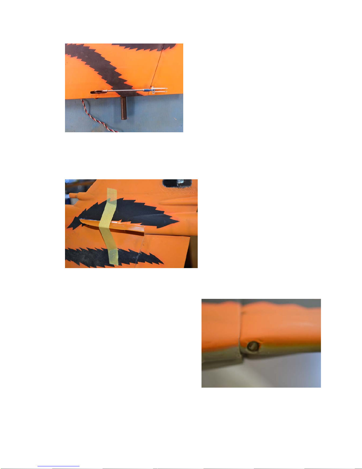
Fin & Rudder
Your fin and rudder come pre-hinged, first check
that you have sufficient movement without the
rudder binding on the sides of the fin.
ed to
Remove the servo and carefully cut a slot in the fin for the arm to protrude. Refit your
ing line or string to guide your servo wire
The rudder can easily be removed by unscrewing
the hinge pin at the bottom of the rudder and
removing it. The fin then can then be trimm
ensure that sufficient movement is gained without
binding.
Temporarily fit your chosen rudder servo
opening for the servo arm.
in the bottom of the fin and mark the
servo and use a small weight on a bit of fish
through the fin.
FEI BAO Mirage 2000 Apr 14
6
Using a straight edge line up the servo
with the intended position of the
rudder horn. Once marked carefully cut
a slot in the rudder to accept the horn,
ensure that the horn is in line with the
servo arm and that the hole in the horn
is positioned over the hinge line. Using
a high strength glue like Hysol or
Aeropoxy glue the horn into the rudder.
(Note: The photos show two horns used,
only one is supplied and is sufficient for
this task.)
Connect all linkages and check for smooth operation with no binding.
Wings
As for the Rudder, check for adequate
movement of the elevon with no binding and if
insufficient remove the hinge pin, located at the
wing tip, and shape the rear of the wing to
ensure adequate movement of the control
surface, refit the hinge pin once satisfied.
arm
Carefully mark the position of the
fences on the top of the fin and cut
a small slot. Using hysol or similar
glue the fences to the top of the
fin.

FEI BAO Mirage 2000 Apr 14
7
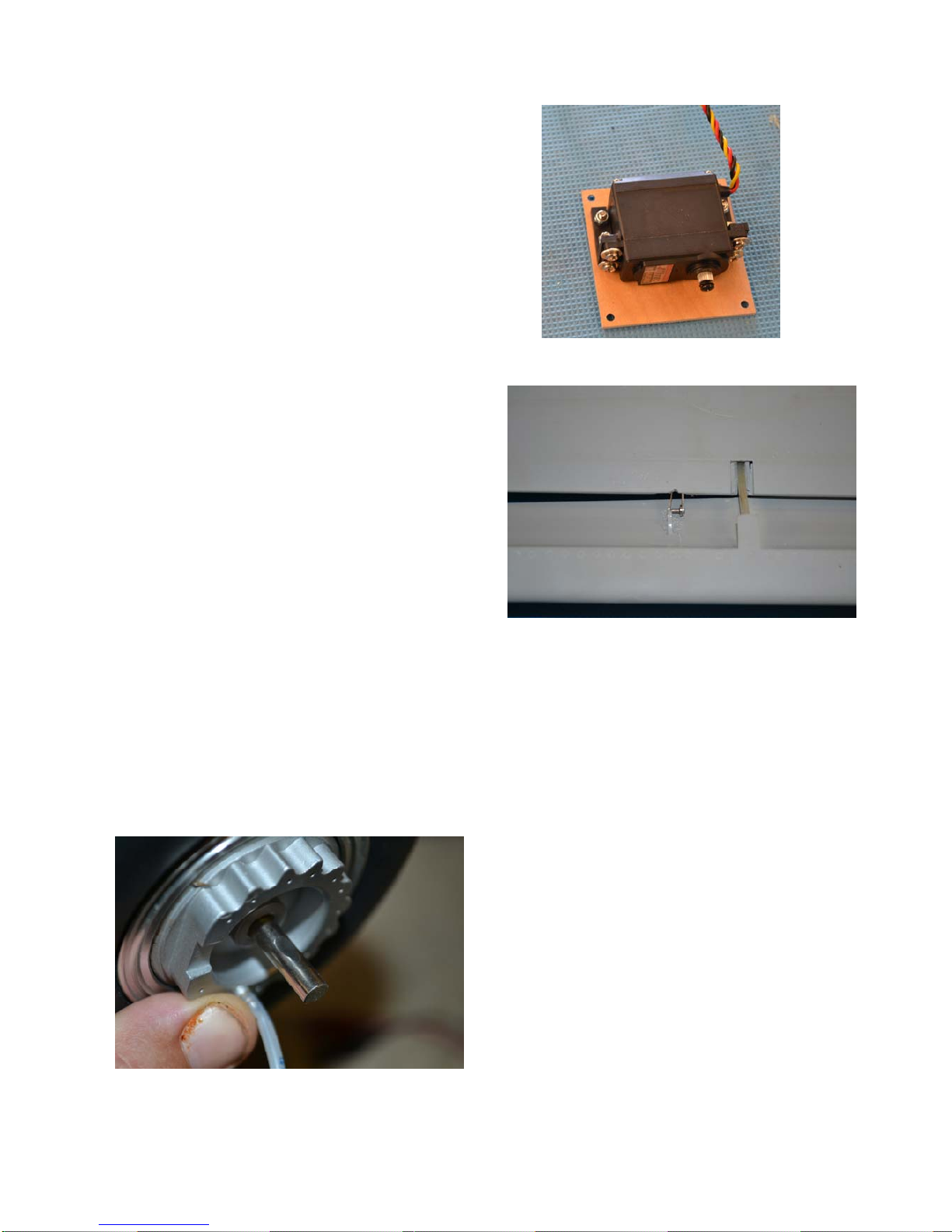
Remove the servo cover for the
elevon and with the mounting
hardware supplied fit your servo.
Given the size of this control
surface it is important that a
premium quality, high torque
servo is used.
Fit the control rod between the
servo and the elevon and ensure
adequate movement of the surface.
It is very important to ensure that
there is no free play in the linkage
system as this may induce flutter
and the loss of control. Ensure all
lock nuts are secured.
A slot has been cut into the elevon for the
control horn, fit the horn using hysol.
(Note - the photo shows two horns fitted
but only one is required and supplied).
FEI BAO Mirage 2000 Apr 14
8
As with the elevon, remove the servo cover from
the slat openings and fit your choice of servo
using the mounting hardware supplied.
Locate the two slat pushrods one short and
one a bit longer. Fit the pushrod to the servo
arm and put through the opening in the front
of the wing. Pull the slat forward and fit the
clevis over the horn, then slide the servo into
wing.
Given the space in the wing only a short
trial and error to get the rod lengths correct
atchbox is used to drive the four servos to
portant that there is no binding when the slat is retracted as
and may cause a servo to malfunction or
Remove the main undercarriage and check
that all bolts are secure and apply loctite if
necessary. Remove the axle and grind a
small flat on the shaft where the grub
screw secures the shaft as an added
measure of security.
m
servo arm can be used to ensure there is no
binding on the upper wing surface.
Do this for both servos, it will take some
for both servos to ensure even travel and no binding.
It is recommended that a power box or m
fine tune the travel, it is im
this will increase the load on the system
drain the batteries prematurely, either is undesirable.
Attach the brake airline and secure to the
ain oleo with clips or cable ties (not
supplied) and refit the undercarriage.
FEI BAO Mirage 2000 Apr 14
9
ct
ain
in
Connect the airlines to the retracts and air
brakes. It is a good idea to use a different
colour line for each function, these aids in
setting up the different functions.
There are many different methods of
routing the air line and wiring the picture is
just a suggested option. Which ever
method you adopt ensure that all wiring
and airlines are secured so as not to foul
the operation of the undercarriage.
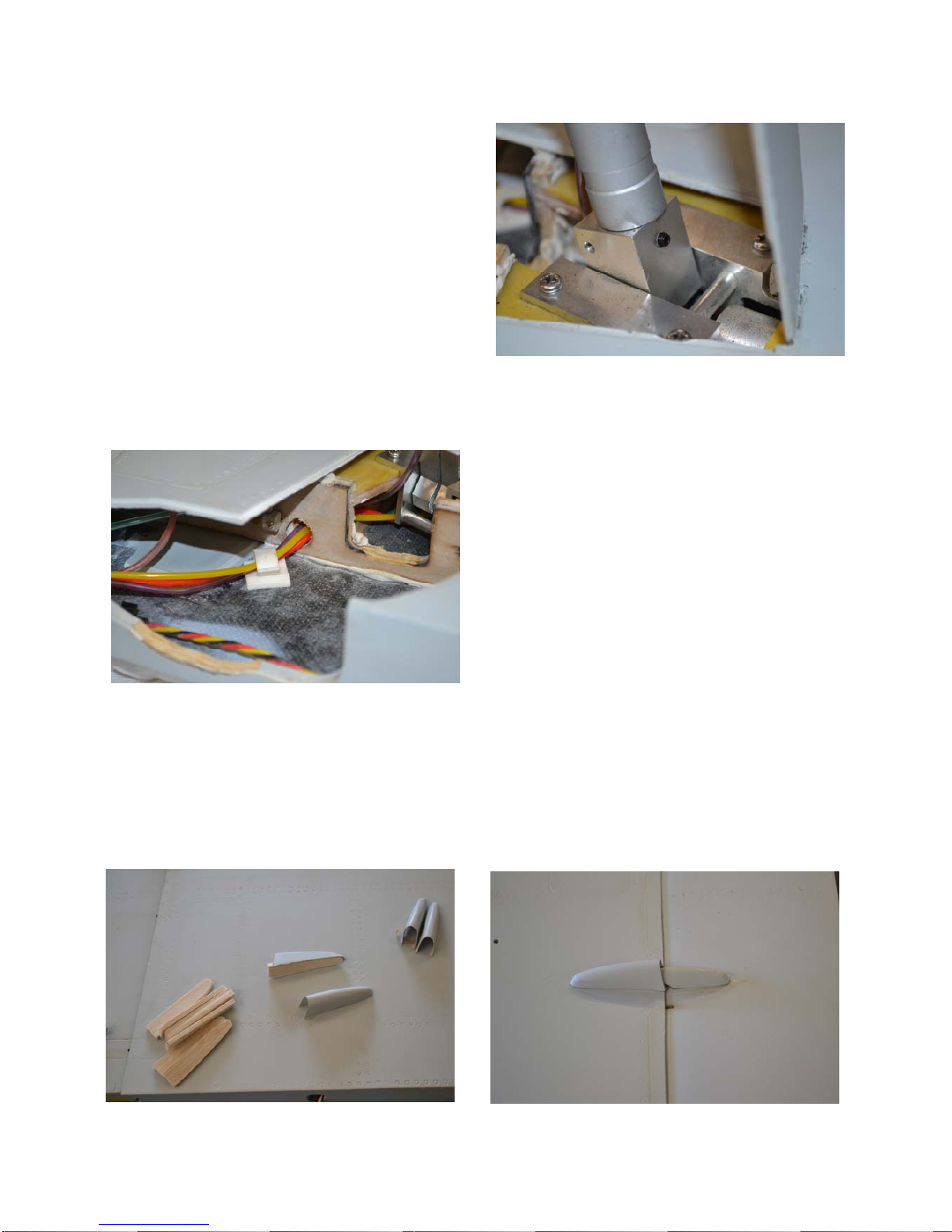
Locate the scale hinge covers and trim any excess from the mouldings. To ensure
good adhesion to the wings it is recommended to make balsa bases for each of the
covers. Once you are happy with the covers fit to the wings with medium CA in the
locations etched in the lower wing surfaces.
A grub screw may also be fitted (grub
screw, drill and tap required) in the retra
trunion to assist in anti-rotation of the m
undercarriage.
These items are not supplied but are a good
idea for added protection against the ma
oleo rotating during take-off and landing.
FEI BAO Mirage 2000 Apr 14
10
Now repeat for the other wing.
Fuselage
Mounting Trays
There are two equipment mounting trays included within the kit and may be used
depending on your chosen system. In the case of this model these were used as
templates for new trays as the cut-outs did not match our intended set up. A further
mounting tray was fabricated to be located above the intake ducts to accommodate the
turbine pump and ECU, pictures of mounting trays are detailed in further assembly
sections below.
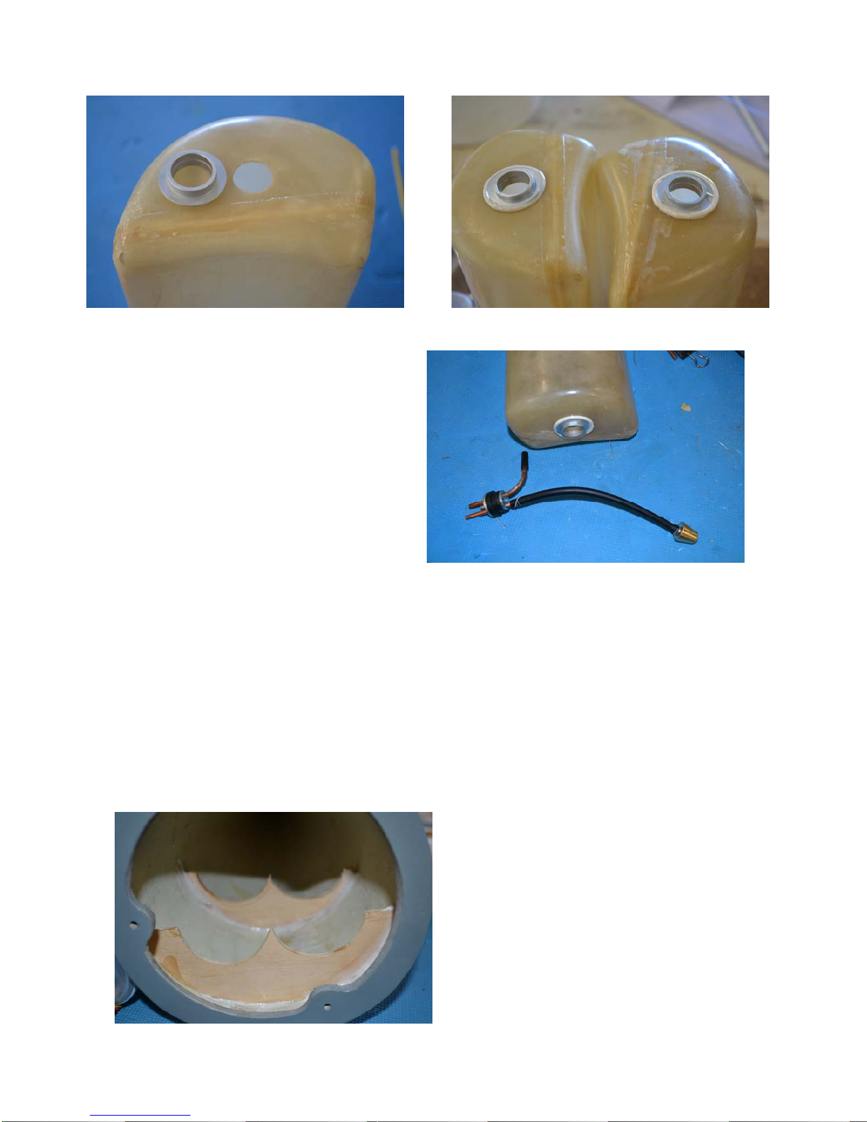
Fuel Tanks
Firstly locate the fuel tanks and the fuel tank components. The fuel system contains
three tanks holding approximately 3.9 litres. If required an additional tank may be
fitted to increase capacity for larger turbines.
The hole in the tank will need to be enlarged with a dremel or similar tool to fit the
fuel tank bung fitting. Once enlarged glue the fitting using hysol and leave to dry.
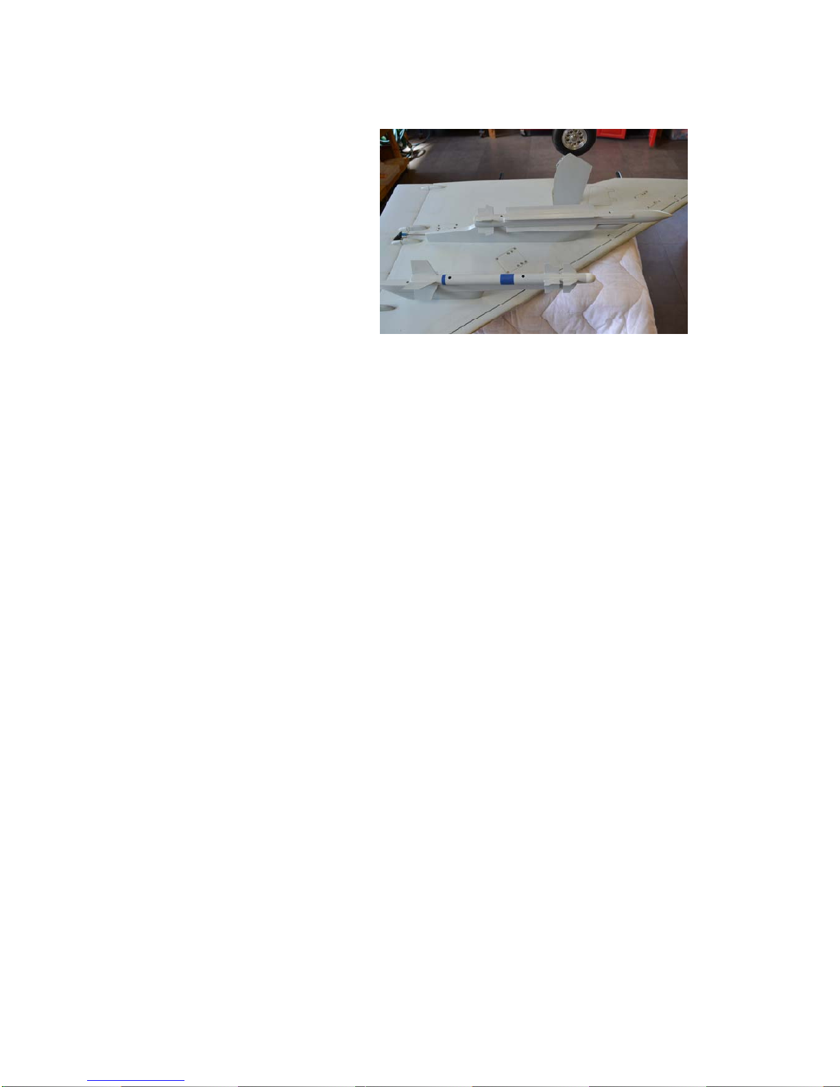
Attach the missile rails to the
wings using the bolts supplied.
Trial fit the missiles and once
satisfied remove as they may be
damaged if left attached to the
wings. Fit just before flight.
FEI BAO Mirage 2000 Apr 14
11
Once satisfied, wash the tank with fuel to ensure all debris is removed. When dry
assemble the tank ensuring all lines are lock wired to prevent air entering the system
and ensuring security. It is a good idea to pressure test the tanks outside of the model
by filling with fuel prior to installation.
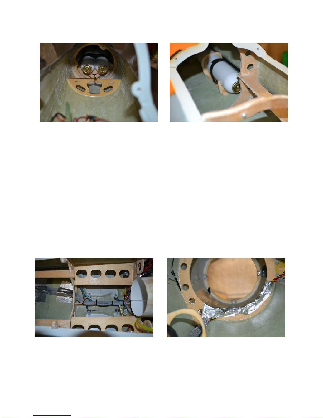
Air System
There are four air tanks supplied, two large and two small. There are a number of
ways to set up the air system and the following is only one recommendation. In the
test model we used the two large tanks for the undercarriage and the two smaller
bottles for the air brakes, brakes and gear doors.
In the test model the two smaller bottles
were fitted to the nose cone while the
two larger bottles were fitted to the rear
of the fuselage.
There is also room below the turbine
rails and front nose section if preferred.
Once dry make up the fuel and vent
lines to ensure adequate movement of
the clunk so it does not bind in the tank
and the vent line goes to the top of the
tank.
FEI BAO Mirage 2000 Apr 14
12
Mounting system for the bottles was fabricated as shown in the pictures.
Connect all air lines to the gear doors and run the lines for the retracts, brakes and air
brakes from the wing connection points to forward fuselage.
Wiring
Run the servo extension cables from their respective positions to the forward fuselage
mounting tray. There are three different access points from the wings to the fuselage
for servo connections. Ensure all wiring is secured to the fuselage to prevent fouling
and chaffing. Pay particular attention to the servo extensions running from the rear
fuselage forward as these should be protected from heat by either a protective sheath
or metal tape.

FEI BAO Mirage 2000 Apr 14
13
Nose Wheel Steering
The supplied forward mounting tray contains a servo mounting position for nose
steering cables will need to be routed
then forward to the nose leg.
In this build it was decided to use a
new mounting tray and make a new
servo mount so that the steering
cables are a direct pull onto the nose
leg.
If using this method it is important to
ensure that the servo position does
not contact the nose leg when
retracted.
Fuel Tank Installation
Determine the position for the tank vent line and fit your desire vent system. Using
high strength Velcro attached the forward fuel tank against the inlet ducts.
There is ample room in front of the main tank to fit your desired UAT, make a mount
as appropriate and fit the UAT.
wheel steering. If you choose to use this system
backwards, around 180 degrees and

FEI BAO Mirage 2000 Apr 14
14
Next install the two saddle tanks
in the engine bay using high
strength Velcro. It may be
required to trim the former to get
the tank lines and bung assembly
to clear the former. In this build a
separate bracket was made to
locate the front of the tanks
against the former. Once fitted
plumb the tanks in your desired
method either in series or parallel
then to the main forward tank.
nd forward inlet duct, if fitted, prior
As we were using a larger turbine
we added an extra dubro tank
located between the two saddle
tanks and above the inlet duct, this
gave another 700mls of fuel.
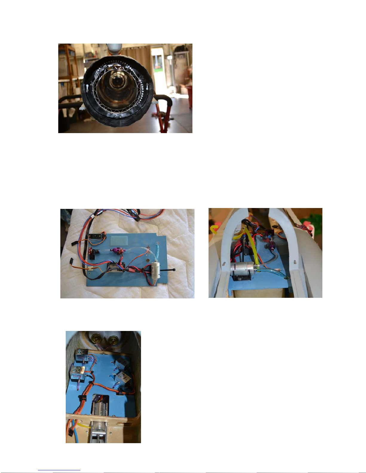
Turbine Mounting
The kit is supplied with a standard bell
mouth and dual wall thrust tube. A carbon
bypass is available as a separate purchase.
The kit is also supplied with an inlet tube
that attaches between the inlet duct and the
front of the turbine. Cut this tube to length
depending on your turbine positioning.
Once the thrust tube is mounted attach the
tail cone and tighten.
Mount your turbine as per manufacturer’s inst
important to ensure that the thrust line of the turbine runs do
tube to avoid hot spots and an offset thrust line.
Note: it will be necessary to remove the turbine a
to fitting the two saddle tanks.
ructions on the turbine rails. It is very
wn the centre of the thrust
FEI BAO Mirage 2000 Apr 14
15
The supplied thrust tube should be
good for turbines up to 16 Kg thrust
but may deform if larger engines are
used.
In this build an 18 Kg thrust turbine
was used so a larger thrust tube was
purchased separately. For this set up
the bypass was not used. (larger
thrust tube shown)
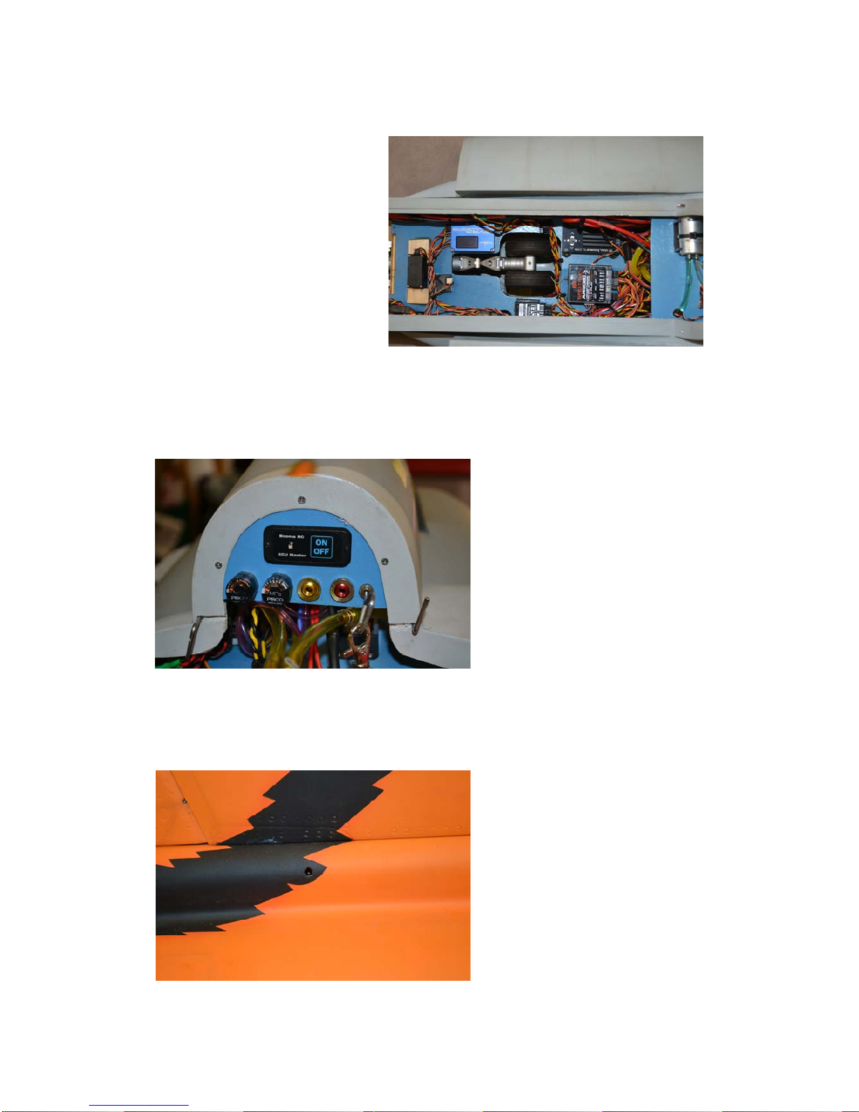
Turbine Controls
To accommodate the turbine controls for this build we fabricated a tray to mount
above the inlet ducts.
This allowed the electronics to be better spaced, as there is limited space available.
Air System Valves
The front mounting tray wa
valves. There are m
requireme
valves which you will n
valve.
All air lines were routed
plastic then up through the mounting tray to the air
valves. This way the airlines are contained and out of
the way. Ensure you leave enough slack in the air lines
ove this tray if required.
s used to house the air
echanical valves supplied with the
kit which are adequate to undertake the air system
nts. In this build we chose to use electronic
eed 3 x 2 way valves and a brake
under the mounting tray in
to rem
FEI BAO Mirage 2000 Apr 14
Main System Mounting Tray
fa
Control Panel
A control panel was made to fit in
the forward opening of the turbine
compartment.
All aircraft services are accessed
on this tray or the lower deck
below making it easy prepare for
flight.
Final Assembly
Attach the fin to the fuselage
using the prepositioned internal
bolt.
A new front system tray was
bricated using the supplied tray
as a template. Arrange your
chosen system in the desired
position and connect the power
and servo lines.
Don’t install the batteries at this
stage as their position can be used
to balance the model without
using lead.
16

FEI BAO Mirage 2000 Apr 14
17
the intakes
Attach the refuelling probe, flare dispenses, centre fuselage tank mount and rear
fuselage fairing to their respective positions.
Position the front strakes on the fuselage side and
cut a slot for them to insert.
Using hysol attach these to the sides of
and allow to dry.
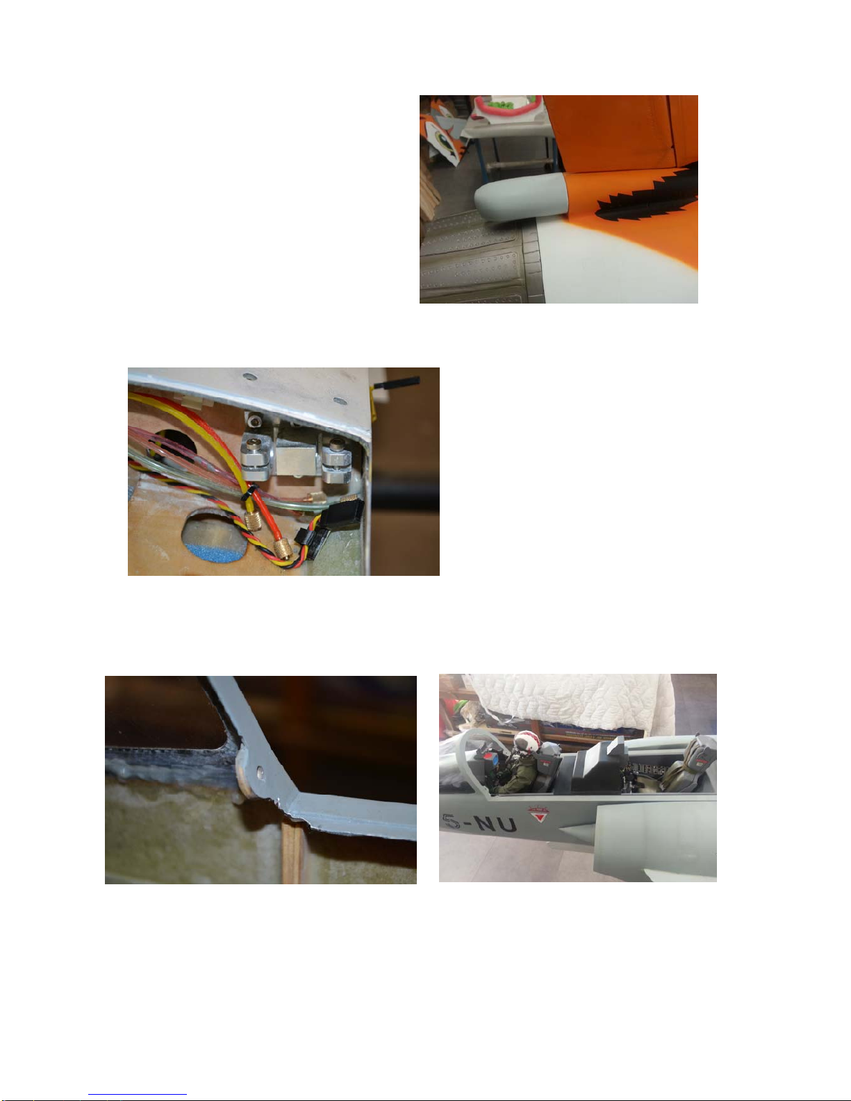
FEI BAO Mirage 2000 Apr 14
18
Its best to screw on this piece to the tail
of the Mirage prior to fitting the thrust
tube as it needs to be screwed from the
inside.
Insert bolts into the wing attachment
points
Trial fit the cockpit and if necessary trim the canopy lugs to ensure an easy fit.
FEI BAO Mirage 2000 Apr 14
19
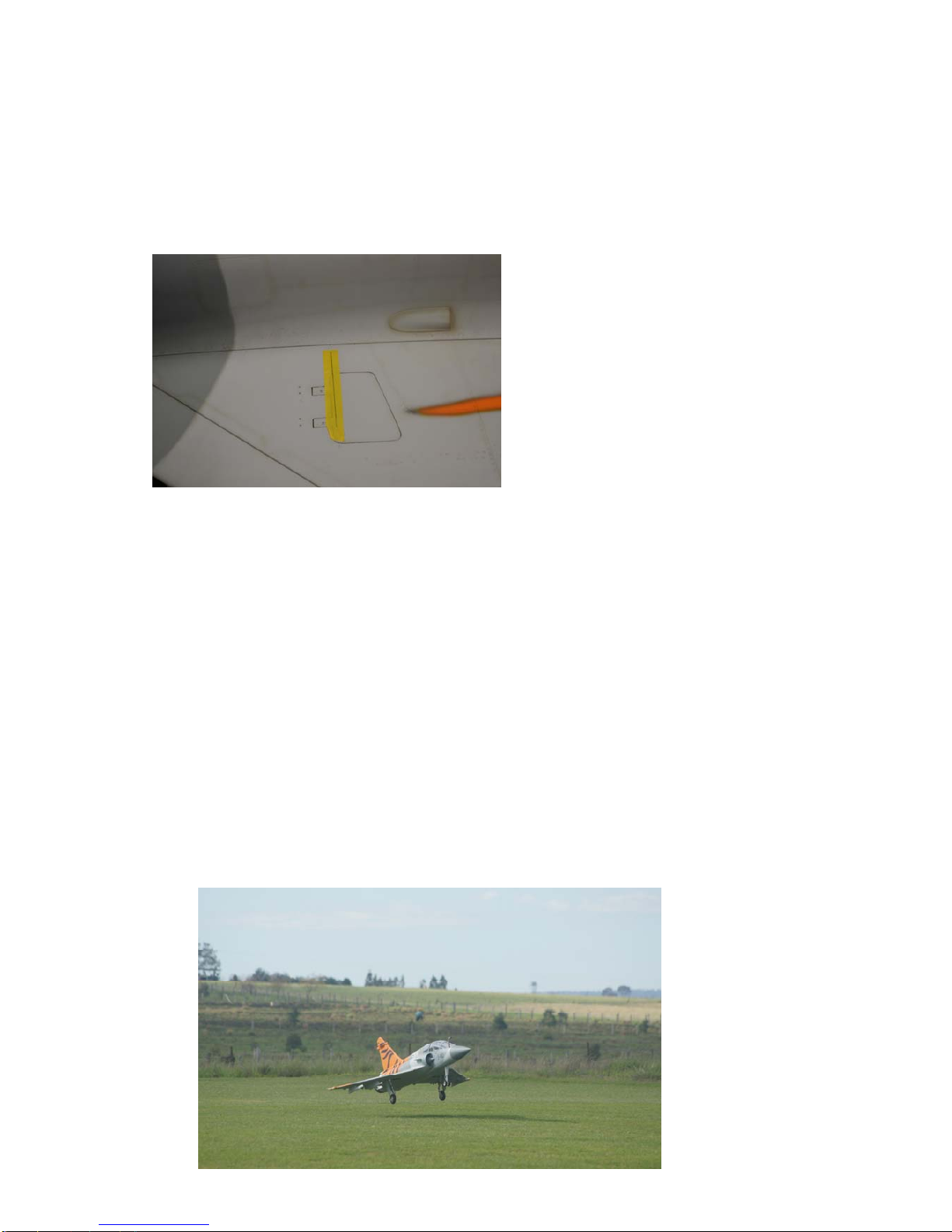
Balance and Battery Position
It is important to get the balance of your model correct. The initial balance point is
400mm from the point where the wing meets the fuselage. Ensure the wheels are
retracted and the UAT is full. Move your chosen batteries around the fuselage to get
a good balance.
The position indicated above is good
for first flights and may be adjusted,
slightly, to conform to your
respective flying style.
Once balance is achieved, secure the
batteries in the fuselage to maintain
balance. For this build the batteries
are located in the nose cone, this is a
result of using a larger turbine and
heavier thrust tube, no lead was
required to achieve balance.
System Test and Control Throws
Once you are satisfied with the balance test all systems for correct operation, this
includes direction of all control surfaces, retracts, brakes and speed brakes, turbine
ground run and range check.
The following control throws were used for this model:
Ailerons 20 mm up and down with 40% expo
Elevator 45mm up and down with 30% expo
Rudder As much as possible with 10% expo
LE Slats 15 to 20 mm
Nose wheel If possible have two settings, one for taxi with large movement and
one for take off with limited movement.
C of G 400 - 430 mm measured from where the wing meets the fuselage
You have now completed construction, enjoy flying your FeiBao Mirage 2000.
Table of contents
Other Fei Bao Toy manuals

Fei Bao
Fei Bao SU-27 User manual

Fei Bao
Fei Bao Mirage F1 User manual

Fei Bao
Fei Bao Velox User manual

Fei Bao
Fei Bao T45 User manual

Fei Bao
Fei Bao EF2000 User manual

Fei Bao
Fei Bao Velox XL User manual

Fei Bao
Fei Bao hawker hunter User manual

Fei Bao
Fei Bao F18-f User manual

Fei Bao
Fei Bao F-4 Phantom II User manual

Fei Bao
Fei Bao L-39 User manual


Popular Toy manuals by other brands


Tiger Electronics
Tiger Electronics Pooh Poppin' Piano 87-001 instruction manual

National Geographic
National Geographic Epic Forts manual

Step 2
Step 2 Disney/Pixar Cars 3 Ride Around Racer 8747 manual

Ready 2 Folo
Ready 2 Folo The Party Stadium Assembly instructions

Trix
Trix 11203 manual

Eduard
Eduard 49 737 Assembly instructions