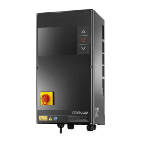
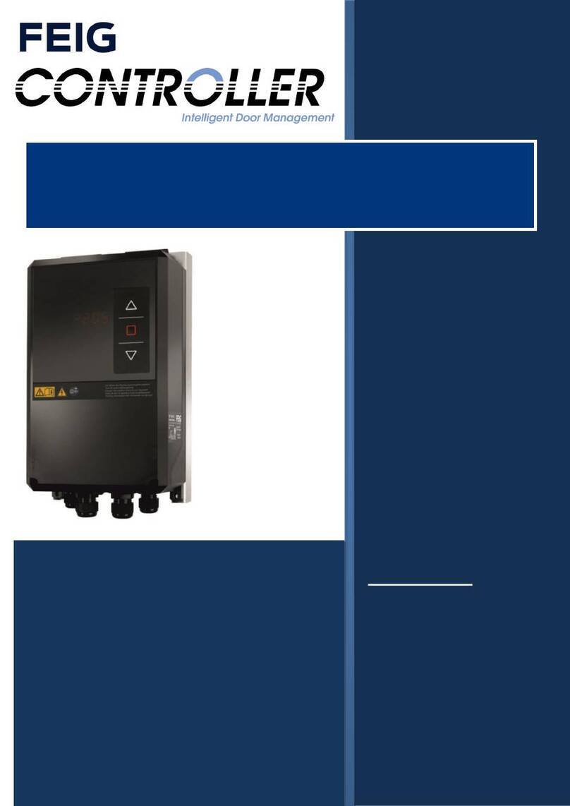
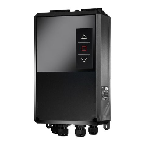
Feig Electronic TST FUZ2-A User manual

DE
ACHTUNG! WICHTIGE SICHERHEITSANWEISUNGEN!
Den Hinweisen auf Seite 3 dieser Montageanleitung ist Folge zu
leisten.
GB
ATTENTION! IMPORTANT SAFETY INFORMATION!
Follow the instructions on page 3 of this manual.
FR
ATTENTION! IMPORTANTES INDICATIONS DE SÉCURITÉ!
Les instructions de la page 3 de cette notice de montage doivent
être observées strictement.
NL
LET OP! BELANGRIJKE VEILIGHEIDSINSTRUCTIES!
Volg de instructies op pagina 3 van deze montagehandleiding
op.
IT
ATTENZIONE! INDICAZIONI SULLA SICUREZZA
IMPORTANTI!
Prestare attenzione alle note alla pagina 3 delle presenti
istruzioni di montaggio.
ES
ATENCION INDICACIONES IMPORTANTES DE SEGURIDAD!
Deben seguirse las indicaciones detalladas en página 3 de
estas instrucciones de montaje.
Attention
Important Safety
Information
These instructions must
be observed to ensure
personal safety.
Store these instructions
safely.
Assembly instructions
Installation, commissioning, utilization and maintenance
TST FUZ2
Versions:
-A/ -B/ -C/ -CX /
-CGH / -CXGH
/ -LGH
Nastavitve str 43 in 45.
Pazi v angleščini so druge kratice
na ekranu.
Glej tudi kratka navodila!

TST Assembly instructions FUZ2 -A/-B/-C/-CX/-L
FEIG ELECTRONIC GmbH Page 2 of 71 FUZ2-A-B-C-CX-L_Montageanleitung_GB_10.docx
Notes
Copyright 2015 by
FEIG ELECTRONIC GmbH
Lange Straße 4
D-35781 Weilburg
Tel.: +49 6471 3109 0
www.feig.de
Version:2017-06-14
This edition replaces all earlier versions.
The specifications in this document are subject to change without notice.
The transmission and reproduction of this document, and utilization and disclosure of its contents
are not permitted unless expressly authorized. Violations will result in liability for damages. All
rights, including rights created by patent grant or registration of a utility model or design, are
reserved.
This Manual is directed especially at persons involved with commissioning the TST FUZ2 door controller of
FEIG ELECTRONIC GmbH. The installation and commissioning of the controller shall only be carried out by
officially trained electrical experts who are familiar with the safety standards of electrical drive and
automation technology.
The distributor of the machine is solely responsible for the completeness of the operating instructions for the
machine (in this case the door). The installation instructions for the door controller that is installed by the
manufacturer of the door shall be supplied in one of the languages of the European Community that is
accepted by the manufacturer of the machine.
This Manual shows only a small range of the controllers functions and provides no warranty of properties.
Additional functions and descriptions for individual door functions as well as more precise specifications for
the controller and hazard warnings are available in the main description.
The compilation of the information in this document has been done to the best of our knowledge and with
due diligence. FEIG ELECTRONIC GmbH does not warrant the correctness and completeness of the
information in this document. In particular, FEIG ELECTRONIC GmbH cannot be held liable for
consequential damages due to incorrect or incomplete information.
In spite of the best efforts, mistakes cannot be avoided completely and we will always gratefully accept any
information in this respect.
The installation recommendations contained in this document presume favorable general conditions.
FEIG ELECTRONIC GmbH assumes no liability for the proper operation of the equipment in third-party
environments.
FEIG ELECTRONIC GmbH provides no warranty that the information in this document is not subject to
foreign copyrights. By furnishing this document, FEIG ELECTRONIC GmbH does not grant any licenses to
its own or foreign patents or any other intellectual property rights.
Only the direct contracting parties shall be entitled to warranty claims against FEIG ELECTRONIC GmbH;
warranty claims are non-transferable. The warranty covers only products supplied by FEIG ELECTRONIC
GmbH. There are no express warranties except as listed above.
The description of the products, their utilization, capabilities and performance specifications shall not be
considered as warranted properties and are subject to technical change.

General information about this document
Language of the original operating instructions: German
The functional description employs the following characters to indicate the different danger areas and useful tips.
ATTENTION
indicates a risk to persons if the procedure is not
carried out as described.
WARNING
indicates that the controller is at risk.
points out information which is IMPORTANT
to the operation of the door controller and/or the
door.
points out information which is useful but not essential
for the use of the door controller

TST Assembly Instructions FUZ2-A/-B/-C/-CX/-L
FEIG ELECTRONIC GmbH Page 2 of 71 FUZ2-A-B-C-CX-L_Montageanleitung_GB_10.docx
DE
ACHTUNG! WICHTIGE SICHERHEITSANWEISUNGEN!
Für die Sicherheit von Personen ist es wichtig diesen Anweisungen Folge zu leisten. Diese Anweisungen
sind aufzubewahren.
Diese Montageanleitung finden Sie im Downloadbereich unter www.feig.de. Bitte loggen Sie sich mit
folgenden Zugangsdaten ein: Username: Download / Password: feig
GB
ATTENTION! IMPORTANT SAFETY INFORMATION!
These instructions must be observed to ensure personal safety. Store these instructions safely.
These installation instructions are available from the download area at www.feig.de. Please sign in with the
following details: Username: Download / Password: feig
FR
ATTENTION! IMPORTANTES INDICATIONS DE SÉCURITÉ!
Pour la sécurité des personnes, il est important de respecter les consignes en question. Les présentes
consignes doivent être conservées en lieu sûr.
Les instructions de montage sont téléchargeables dans la zone téléchargements de www.feig,de. Prière de
vous logger avec les données suivantes: Nom d'utilisateur : Download / Mot de passe: feig
NL
LET OP! BELANGRIJKE VEILIGHEIDSINSTRUCTIES!
Voor de veiligheid van personen is het belangrijk om deze aanwijzingen op te volgen. Deze aanwijzingen
dienen bewaard te worden.
Deze montagehandleiding kunt u vinden als download op www.feig.de. Gelieve de volgende
toegangsgegevens te gebruiken: gebruikersnaam: Download / wachtwoord: feig
IT
ATTENZIONE! INDICAZIONI SULLA SICUREZZA IMPORTANTI!
Per la sicurezza personale è importante attenersi scrupolosamente a queste indicazioni. Queste indicazioni
vanno conservate.
Le presenti istruzioni di montaggio sono disponibili nell’area download del sito www.feig.de. Effettuare il login
con i seguenti dati d'accesso: Nome utente: Download / Password: feig
ES
ATENCIÓN INDICACIONES IMPORTANTES DE SEGURIDAD
Para la seguridad de las personas es importante seguir estas indicaciones. Deben guardarse estas
indicaciones.
Puede encontrar estas instrucciones de montaje en el área de descarga en www.feig.de. Se ruega iniciar
sesión con los siguientes datos de acceso: Nombre de usuario: Download / Password: feig

TST Assembly Instructions FUZ2-A/-B/-C/-CX/-L
FEIG ELECTRONIC GmbH Page 3 of 71 FUZ2-A-B-C-CX-L_Montageanleitung_GB_10.docx
1
2
3
Download
feig

TST Assembly Instructions FUZ2-A/-B/-C/-CX/-L
FEIG ELECTRONIC GmbH Page 4 of 71 FUZ2-A-B-C-CX-L_Montageanleitung_GB_10.docx
Contents
Notes 2
General information about this document 1
1General description and intended use 6
2Safety information 7
3Installation of the controller 8
4Housing options 9
4.1 Housing option 1 / small housing...............................................................................................9
4.1.1 Installation position of the cover................................................................................................9
4.2 Additional heat sink for small housing....................................................................................10
4.3 Housing option 2 / large housing .............................................................................................13
5Electrical connection 14
5.1 Power supply voltage without main switch.............................................................................15
5.2 Power supply voltage with main switch ..................................................................................16
5.3 Motor and brake .........................................................................................................................17
5.4 Safety edge on the integrated evaluation................................................................................18
5.4.1 Optical safety edge .................................................................................................................18
5.4.2 Electrical resistance safety edge ...........................................................................................19
5.5 Safety edge at the 2nd Integrated evaluation (input 10) ........................................................20
5.5.1 Optical safety edge .................................................................................................................20
5.5.2 Electrical resistance safety edge ...........................................................................................21
5.5.3 Digital input .............................................................................................................................21
5.6 Light curtain TST LGB...............................................................................................................22
5.6.1 Installation of the TST LGB.....................................................................................................22
5.6.2 Connection of the TST LGB....................................................................................................23
5.7 Limit switchconnection .............................................................................................................24
5.7.1 Absolute encoder TST PE or TST PE FSB with WICAB system............................................24
5.7.2 Absolute encoder TST PD......................................................................................................25
5.7.3 Absolute encoder DES...........................................................................................................26
5.7.4 Mechanical limit switches........................................................................................................27
5.8 Photo eye....................................................................................................................................28
5.9 External triggering devices.......................................................................................................28
5.10 Traffic light connection .............................................................................................................29
5.11 Overview of outputs...................................................................................................................30
5.12 Overview of inputs.....................................................................................................................31

TST Assembly Instructions FUZ2-A/-B/-C/-CX/-L
FEIG ELECTRONIC GmbH Page 5 of 71 FUZ2-A-B-C-CX-L_Montageanleitung_GB_10.docx
6Optional plug-in and expansion cards 32
6.1 Wireless receiverTST SFFE.......................................................................................................32
6.2 Induction loop detector TST Suvek..........................................................................................33
6.3 Safety edge monitor TST SURA................................................................................................34
6.4 Expansion card RFUxK .............................................................................................................35
6.5 Interface card TST RFUxFCOM.................................................................................................36
6.6 Auxiliary relay TST SRA............................................................................................................37
6.7 LCD text display.........................................................................................................................38
7General operating instructions to set parameters 39
7.1 Open the parameter operation mode.......................................................................................39
7.2 Editing a selected parameter ....................................................................................................40
7.3 Exit parameter operation mode................................................................................................40
7.4 Execute a reset...........................................................................................................................40
7.5 Entry into the extended parameter configuration mode........................................................40
8Basic settings 41
8.1 Automatic query of basic data..................................................................................................41
9Startup… 43
9.1 …with absolute encoder or incremental encoder...................................................................43
9.2 … with mechanical limit switches ............................................................................................44
9.3 … with light curtain TST LGB ...................................................................................................45
9.4 Renewed request for "learning" limit positions......................................................................47
9.5 Boost / increase in performance forlow speeds.....................................................................47
10 Movement optimisation for the door 48
10.1 Opening of the door...................................................................................................................48
10.2 Closing of the door ....................................................................................................................49
10.3 Pre-limit switch setting..............................................................................................................50
10.4 Ramp configuration ...................................................................................................................50
10.5 Correction of the final positions...............................................................................................50
11 Functions 50
12 Messages 51
12.1 Error messages..........................................................................................................................51
12.2 Information messages...............................................................................................................61
13 General messages 63
14 Specifications 66
15 Directives and Standards 68

TST Assembly Instructions FUZ2-A/-B/-C/-CX/-L
FEIG ELECTRONIC GmbH Page 6 of 71 FUZ2-A-B-C-CX-L_Montageanleitung_GB_10.docx
1 General description and intended use
The device described below is an electronic control system for motor-driven industrial or commercial doors in
accordance with EN 13241. A fully integrated frequency converter with power output stage can gently control
the door with variable opening and closing speeds. The control system TST FUZ2 is designed to handle
electrical induction motors with a power consumption of up to 1.5 kW and a 230 V supply
In addition to controlling the motor that drives the door, the controller can be used for the following tasks:
Positioning the door at and between its final positions (open, close and intermediate positions)
To control the drive to run at different speeds (integrated frequency converter)
Evaluation of the security sensors on the door (e.g. safety edge monitoring, pull-in protection, etc.)
Evaluation of additional safety equipment on the door (e.g. photo eyes, light curtains, etc.)
Evaluation of control circuits at the door (e.g. pull switch, radio, inductive loops, etc.)
Evaluation of emergency stop controls
Electronically protected 24V low-voltage power supply for sensors and control devices
230 V power supply to external units
Control of application-specific outputs (such as relays for door position reporting)
Generation and output of diagnostic messages
Configuration of application-specific parameters for different levels of access of the different user groups
Control of input/output expansion modules:
oTST SFFE: plug-in module wireless remote control
oTST FSx: wireless Security System
oTST SURA: Safety edge evaluation board
oTST SUVEK: plug-in module for inductive loop detection
oTST RFUxK: universal display and input/output module
oTST RFUxFCOM: interface module for the lock-door applications, etc.
oTST SRA: connectable module auxiliary relay
oTST LCD / clear text: Clear text display with 2x16 signs.
oEvaluation of interface signals for remote control, diagnosis and configuration of the parameters
of the door

TST Assembly Instructions FUZ2-A/-B/-C/-CX/-L
FEIG ELECTRONIC GmbH Page 7 of 71 FUZ2-A-B-C-CX-L_Montageanleitung_GB_10.docx
2 Safety information
ATTENTION
Failure to observe the safety advisories can result in physical harm or damage to the controller.
When starting up and operating the controller, the following important safety advisories as well as the installation
and wiring notes must be strictly observed:
In accordance with the EC Machinery Directive only qualified personnel shall install the device on the doors or at
the drive units for doors or bring them together. The respective safety requirements for the entire door (machine) must
be aligned with the possibilities to meeting these safety requirements on the controller.
Improper integration of the controller into the door complex –e.g. missing sensors, incorrect parameters, speed set
excessively high, etc. –presents the risk that the door is operated without adequate safety precautions.
The commissioning of this controller is prohibited until it has been properly attached to the door that conforms with
the EC Machinery Directive and for which an EC declaration of conformity according to Annex II of the Directive
was obtained.
The following information describes standard applications that may not necessarily match the actual application. The actual
application is provided by the manufacturer of the door as part of the overall documentation or as part of the operating
instructions of the door.
Any installation, startup and maintenance work must only be performed by qualified specialists. In particular, the
following regulations must be observed: VDE0100, EN 50110 (VDE0105), EN 60204 (VDE0113), EN 50178 (VDE0160), EN
60335 (VDE0700), fire protection codes, accident prevention regulations as well as the relevant regulations for industrial
doors and machine safety standards (EN ISO 13849, EN 62061)(ZH1/494, EN12453, EN12978)
This device is not intended for use by persons (including children) with limited physical, sensory or mental abilities or with a
lack of experience and / or knowledge, unless they are supervised by a person responsible for their safety or if they have
received instructions on the use of the device. Children should be supervised to ensure that they do not play with the device.
Keep remote controls away from such persons.
A device mark (nameplate with name and address of the manufacturer, serial number, model number, supply voltage and
temperature range) must be applied by the user.
The example of the warning label must be attached to the motor near the motor terminal board.
Type label (example):
Warning notice label (example):
The safety advisories mentioned in this document make no claim to completeness. If you have questions about the
product, contact your vendor.
The manufacturer has carefully checked and inspected the hardware and software, but no warranty is given for a
complete absence of errors.
Dispose of the product at the end of its life cycle in accordance with the applicable
statutory provisions.

TST Assembly Instructions FUZ2-A/-B/-C/-CX/-L
FEIG ELECTRONIC GmbH Page 8 of 71 FUZ2-A-B-C-CX-L_Montageanleitung_GB_10.docx
3 Installation of the controller
ATTENTION
IMPORTANT INSTRUCTIONS FOR SAFE INSTALLATION!
Observe all instructions; incorrect installation can result in serious injuries.
When installing the controller, the system must be turned off.
The controller may be opened only if all the poles of the supply voltage have been turned off. It is not
permitted to turn on or to operate the controller when it is open.
Disconnect all supply circuits before opening the housing for access to the terminals.
Before the installation, check the controller for transport or other damages. Under some conditions a
damaged controller may result in significant consequential damage to the controller as well as hazards to
the user.
The controller must never be operated with a damaged membrane keypad or Display window. Damaged
keypads and Display windows must be replaced.
WARNING
Do not touch any electronic parts, in particular the components of the processor circuit. Electronic
components can be damaged or destroyed by electrostatic discharge.
Before opening the cover of the enclosure, ensure that no drilling swarf can fall into the housing from the
cover.
When installing the controller it is important to ensure that it is not subject to mechanical stresses.
Unused cable entries must be sealed to maintain the requirements of IP54.
Ensure that the cable entries are not subjected to mechanical stresses, in particular tensile stresses.
The controller must never be operated without the CEE-plug except when the supply voltage can be cut
all poles by an installed main switch. The main switch and the CEE-plug must be within easy reach.
A not rotating motor is no indication of the galvanic isolation from the power grid! The line supply
connection terminals, motor terminals and terminals for the brake resistor can still carry dangerous
voltages, e.g. under stop or emergency stops.
If the supply cable is damaged, it must be replaced by the manufacturer or another qualified person in
order to avoid danger (like connection type Y EN 60335-1)
When moving the door in deadman mode, ensure that the operator has an unobstructed view of the door
area. In this mode, safety equipment such as safety edge and photo eye may have been defeated. If this
is not possible for structural reasons, you must ensure that this mode is only accessible to appropriately
trained personnel or that the feature is disabled altogether.
To prevent damage to the keypad, do not use pointed objects to operate the keys. The keypad is only
designed to be operated by human fingers.
Depending on the type of the door it may be necessary that the door can only be operated when it is
within visual range. In these cases, no remote control (e.g. wireless) may be used to issue commands.
It is important to ensure that the controller is installed with the wall spacers that are supplied to guarantee
that the power stage can dissipate heat as necessary.
The control unit should not be mounted on flammable surfaces (e.g. wood ≤ 2 mm thickness) or in
environments with highly flammable substances (e.g. carpentry).
When the controller is installed in an additional housing, e.g. in a barrier housing, care must be taken to
provide a sufficient volume of air around the controller. This must be at least 0.02 m3.
Should cooling not be sufficient, an additional heat sink may be inserted between the controllers housing
and the additional housing to dissipate the heat to the outside (see chapter 4.2 Additional heat sink for
small housing).

TST Assembly instruction FUZ2 -A/-B/-C/-CX/-L
FEIG ELECTRONIC GmbH Page 9 of 71 FUZ2-A-B-C-CX-L_Montageanleitung_GB_10.docx
4 Housing options
There are two different housing options available for different device options.
50°C
-20°C
4.1 Housing option 1 / small housing
This type of housing is used for controller types TST FUZ2-A, TST FUZ2-B, and -CX.
The expansion card TST RFUxK can be used in this housing only in combination with
controller type TST FUZ2-B.
Min. 100mm
Min. 100mm
1x230VAC,
N, PE Abstandhalter
Figure 1: Installation in small housing
300
160
80
Floor
Ca. 1300
Figure 2: Drilling template small housing
4.1.1 Installation position of the cover
Figure 3: Installation position of the cover

TST Assembly instruction FUZ2 -A/-B/-C/-CX/-L
FEIG ELECTRONIC GmbH Page 10 of 71 FUZ2-A-B-C-CX-L_Montageanleitung_GB_10.docx
4.2 Additional heat sink for small housing
If the controller is installed in an additional housing so that the cold air supplied to the heat sink is not
sufficient, for example, in barrier housings, an additional heat sink must be inserted between the controllers
housing and the additional housing to dissipate heat to the outside. This additional heat sink is mounted, for
example, on the barrier housing and the controller is mounted above it without the spacers, so that the
additional heat sink is clamped between the controller and the cabinet.
The additional heat sink must have the following design:
Figure 4: Additional heat sink

TST Assembly instructions FUZ2 -A/-B/-C/-CX/-L
FEIG ELECTRONIC GmbH Page 11 of 71 FUZ2-A-B-C-CX-L_Montageanleitung_GB_10.docx
The additional heat sink must be bolted to the housing and then controller can be installed:
Figure 5: Drilling layout for additional heat sink and controller

TST Assembly instructions FUZ2 -A/-B/-C/-CX/-L
FEIG ELECTRONIC GmbH Page 12 of 71 FUZ2-A-B-C-CX-L_Montageanleitung_GB_10.docx
The following images show the installation of the heat sink with the controller:
Step 1: install additional heat sink
Use the following screws:
Use countersunk screw M4 DIN 965
Step 2: remove the spacer
Do not use spacers!
Step 3: install the controller
All four screws must be
completely recessed!

TST Assembly instructions FUZ2 -A/-B/-C/-CX/-L
FEIG ELECTRONIC GmbH Page 13 of 71 FUZ2-A-B-C-CX-L_Montageanleitung_GB_10.docx
4.3 Housing option 2 / large housing
This type of housing is used for controller types TST FUZ2-CGH, TST FUZ2-B, and -LGH.
Min. 100mm
Min. 100mm
Figure 6: Installation in large housing
415
179
Floor
Ca. 1300
89,5
Figure 7: Drilling template large housing

TST Assembly instructions FUZ2 -A/-B/-C/-CX/-L
FEIG ELECTRONIC GmbH Page 14 of 71 FUZ2-A-B-C-CX-L_Montageanleitung_GB_10.docx
5 Electrical connection
ATTENTION
Any wiring, testing and maintenance work on an open
controller shall only be performed when power has -
been turned off. Pay particular attention to the points
shown under "Safety information".
The controller must never be operated while it is
open.
When the controller has been turned off, dangerous
voltage levels are still present for up to 5 minutes.
During the downtime, no isolation exists between the
amplifier module and the motor terminal.
Touching electronic components is dangerous due to
residual voltages.
Never operate the controller while the cover is
removed.
When the installation was completed, check that the
system was configured correctly and that the safety
system works properly.
The controller may be opened only if all the poles of
the supply voltage have been turned off. It is not
permitted to turn on or to operate the controller when
it is open.
Never operate the controller without having connected
the protective earth conductor. The absence of a
protective earth conductor will result in hazardous
voltages on the controllers housing caused by
terminal capacitances. The RFI filters integrated into
the controller may increase the leakage current up to
a max. of 7 mA (see DIN EN 60335-1 section 16.2).
Prior to delivery, the manufacturer will test individual
units in this respect.
Hazardous voltages remain stored in the DC-bus
capacitors for up to five minutes after power has been
turned off. The discharge time until voltages fall below
60 VDC is a maximum of 5 minutes. Touching internal
controller components within this discharge time is
hazardous.
A defective switching power supply can considerably
increase the discharge time of the DC-bus capacitors
before reaching a voltage less than 60VDC. In this
case, discharge times of up to 10 minutes may be
possible.
The processor circuit is galvanically connected to the
power line. Important: when taking measurements on
the processor circuit , do not use test equipment with
PE reference to the measuring circuit.
The controller must never be operated with a
damaged membrane keypad or Display window.
Damaged keypads and Display windows must be
replaced. To prevent damage to the keypad, do not
use pointed objects to operate the keys. The keypad
is only designed to be operated by human fingers.
If the potential free contacts of the output relays or
other terminals are supplied by an external voltage,
i.e. dangerous voltages that are still present after
switching off the controller or disconnecting power,
you must attach a suitable warning sign to the
housing.
ATTENTION
Disconnect all supply circuits before opening the
housing for access to the terminals.
When moving the door in deadman mode, ensure that
the operator has an unobstructed view of the door
area, since in this mode safety equipment such as
safety edge and photo eyes are defeated.
Parameter settings inclusive the speed as well as all
operations of the safety devices must be checked.
Parameter settings and insertion of jumpers shall only
be performed by properly trained persons.
WARNING
Before turning on the controller for the first time and
after completion of the wiring, check whether all motor
connections are tight on the controller and the motor
side and whether the motor is correctly wired in star or
delta configuration. Loose connections to the motor
usually result in damage to the inverter.
If the 24 V controller voltage is short circuited or
overloaded, the switching power supply will not start up
even though the intermediate circuit capacitors are
charged. The displays remain turned off. The power
supply can only be restarted after eliminating the short
circuit or the overload condition.
To fulfill the conditions of the EMC Directives, only
shielded and separate motor conductors must be used,
with the shield connected on both ends (motor and
controller side) and without any additional connections
in the line. Maximum cable length: 30 m.
Fast running plastic foildoors may produce very high
electrostatic charges. A discharge of these voltages
may damage the controller. Therefore suitable
measures must be taken to prevent electrostatic
discharge.
Turning on or operating the controller in the presence
of condensation is not permitted. This can result in the
destruction of the controller.
Before turning on the controllers supply for the first
time, ensure that the detector/sensor cards (plug-in
modules) have been inserted in the correct locations.
Incorrect insertion of the cards can result in damage to
the controller, likewise the installation of non-approved
third-party equipment.
Connect connection terminals before connecting to the
plug connectors! Only thus is it possible to ensure a
safe contact of the connection terminals to the plug
connectors.

TST Assembly instructions FUZ2 -A/-B/-C/-CX/-L
FEIG ELECTRONIC GmbH Page 15 of 71 FUZ2-A-B-C-CX-L_Montageanleitung_GB_10.docx
Maximum connection diameters for the terminals
on printed circuit boards:
single wire (rigid)
fine wire (with/without
wire end ferrule)
Max. tightening torque
[NM]
motor terminals
2.5
2.5
0.5
Line supplies
2.5
1.5
0.5
screw terminals (catch 5 mm)
2.5
1.5
0.5
plug in terminals (catch 5 mm)
1.5
1.0
0.4
plug in terminals (catch 3.5 mm)
1.5
1.0
0.25
Recheck all wiring connections before turning the
controller on. Incorrect connections may damage the unit.
5.1 Power supply voltage without main switch
PE
N
L
CEE plug 3 poles,
blue Fuse 16A / K- Type
LN
L´ N´ N´
L´
Figure 8: Connecting the power cable
The power plug must be visible and accessible from the control system.

TST Assembly instructions FUZ2 -A/-B/-C/-CX/-L
FEIG ELECTRONIC GmbH Page 16 of 71 FUZ2-A-B-C-CX-L_Montageanleitung_GB_10.docx
5.2 Power supply voltage with main switch
L N
X13
Sicherung
16A/K-Typ
N
N
LPE
PE
L
Figure 9: Connecting the power cable

TST Assembly instructions FUZ2 -A/-B/-C/-CX/-L
FEIG ELECTRONIC GmbH Page 17 of 71 FUZ2-A-B-C-CX-L_Montageanleitung_GB_10.docx
5.3 Motor and brake
M
~~
+
-
3~
T1T2T3
PE
Shielding of the motor
cable
UVW
Shielding of the
motor cable
PE
202122
L´
N´
L´ N´
N´
L´
L´
N´
AC
DC
Connection
example: brake
according to closed
circuit principle
control line
including brake
connection and
limit switch
connection
Brake rectifier
Figure 10: Motor connection
Use a shielded motor cable in order to guarantee error-free operation of the controller. In
addition, no other conductors except the motor connection may be included in this line.
In the case of drive units with an electronic brake, ensure that the brake is equipped with
adequate suppression. We recommend the use of RC-elements for interference suppression
purposes.
For the relay K2 to work as a brake relay, set parameter P.702 = 3201.

TST Assembly instructions FUZ2 -A/-B/-C/-CX/-L
FEIG ELECTRONIC GmbH Page 18 of 71 FUZ2-A-B-C-CX-L_Montageanleitung_GB_10.docx
5.4 Safety edge on the integrated evaluation
Various types of safety edges can be connected, for example:
Electrical safety edge with 1.2 kΩ or 8.2 kΩ terminating resistor.
Dynamical optical system
If one of these types of safety edges is connected when the door control system is switched on it
will be recognized automatically.
If no safety edge is connected, automatic closing of the door is not possible.
Use of additional types of safety edges is possible. Please contact the door manufacturer in this respect.
5.4.1 Optical safety edge
45
44
43
42
41
Spiral cable
Junction
box
41 42
Slack rope
switch
optional slip
door switch
brown
white
Jumper J 800 is
located to the left
and behind terminal
61 - 62
1 3
J800 = 1-2 8,2K 1,2K
J800
Receiver
Transmitter
green
Figure 11: Connection of an optical safety edge
This manual suits for next models
4
Table of contents
Other Feig Electronic Controllers manuals

Feig Electronic
Feig Electronic TST FUF2 Series User manual

Feig Electronic
Feig Electronic TST WU User manual

Feig Electronic
Feig Electronic TST FUF2 Series User manual

Feig Electronic
Feig Electronic OBID i-scan ID ISC.PR101 Installation and operating instructions

Feig Electronic
Feig Electronic TST FU3E Installation manual

Feig Electronic
Feig Electronic TST FUZ2 User manual