Step-by-Step Assembly:
info@feinoptic.com
Page 9
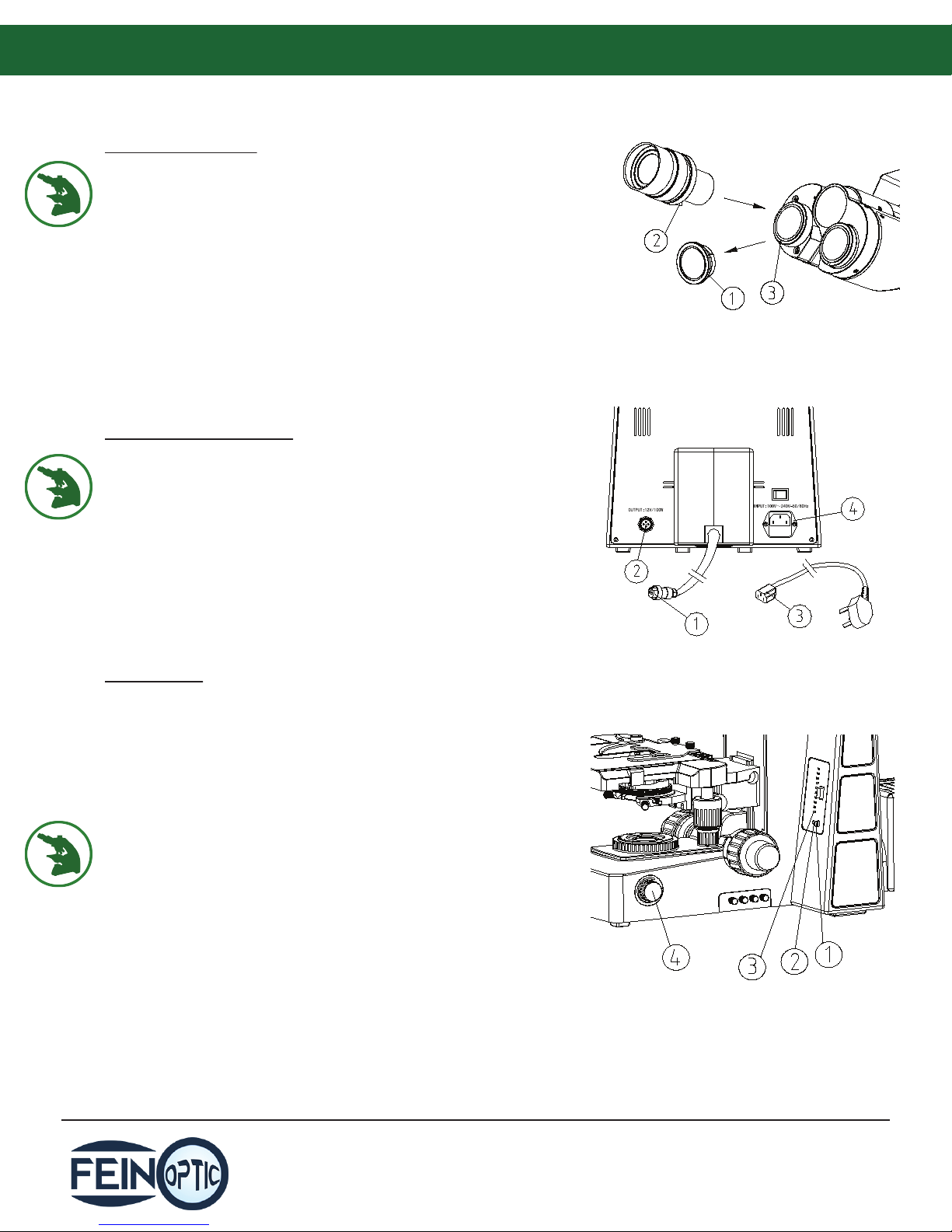
Slide Placement:
Push the slide holder clamp (1) backwards.
Place the slide between the slide holder clamp (1)
and the slide holder (2) with the cover slip facing up.
Rotate the X-Axis knob (4) and the Y-Axis knob (3) to
position the slide in the center under the objective.
Beam Splitter:
When using the trinocular microscope, in order to
send light up to the camera (trinocular) port, pull the
beam splitter (1) out. When the beam splitter is
pushed in all the light will go to the eyepieces.
When it is pulled out part way light will go to the
camera and the eyepieces. And when it is pull out
100%, all light will go to the trinocular port.
Focusing Adjustment:
Place a slide on the stage. Move the 4x objective into
position.
Loosen the upper limit lever (1), then observe
through the right eyepiece. Rotate the coarse
focusing knob (2) until the image appears in the eld
of view, then lock the upper limit lever (1).
The upper limit lever can prevent the objective from
touching the slide when focusing.
The upper limit lever does not aect the ne focus
knob.
Rotate the ne focus knob (3) to obtain a clear
image.
When observing with the 4x or 10x objective, open
both the aperture diaphragm and eld iris
diaphragm to the maximum position and swing out
the front condenser lens.