manuals.online logo
Brands
  1. Home
  2. •
  3. Brands
  4. •
  5. Olympus
  6. •
  7. Microscope
  8. •
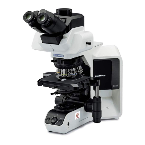
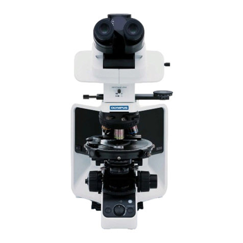
  9. Olympus bx40 User manual

Olympus bx40 User manual

Other manuals for bx40

2

Other Olympus Microscope manuals

Olympus BH2 Series Installation instructions

Olympus

Olympus BH2 Series Installation instructions

Olympus DSX1000 User manual

Olympus

Olympus DSX1000 User manual

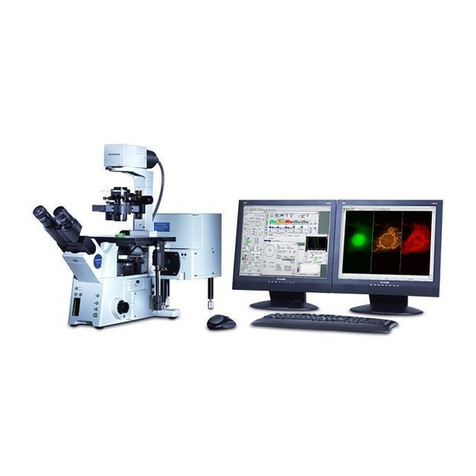
Olympus Fluoview FV1000 Manual

Olympus

Olympus Fluoview FV1000 Manual

Olympus BX3-SSU User manual

Olympus

Olympus BX3-SSU User manual

Olympus BX3-URA User manual

Olympus

Olympus BX3-URA User manual

Olympus SZ-III User manual

Olympus

Olympus SZ-III User manual

Olympus DP26 User manual

Olympus

Olympus DP26 User manual

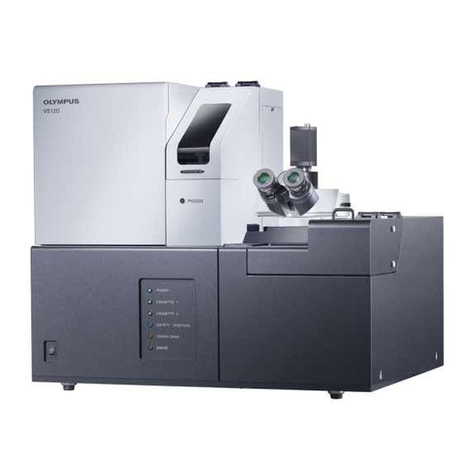
Olympus VS120 User manual

Olympus

Olympus VS120 User manual

Olympus CHA User manual

Olympus

Olympus CHA User manual

Olympus BX53 User manual

Olympus

Olympus BX53 User manual

Olympus SZ61 User manual

Olympus

Olympus SZ61 User manual

Olympus BX53M-P User manual

Olympus

Olympus BX53M-P User manual

Olympus SZ2-ILA User manual

Olympus

Olympus SZ2-ILA User manual

Olympus BHT-111 User manual

Olympus

Olympus BHT-111 User manual

Olympus SZ-III User manual

Olympus

Olympus SZ-III User manual

Olympus CX43-RFAB User manual

Olympus

Olympus CX43-RFAB User manual

Olympus BX63 User manual

Olympus

Olympus BX63 User manual

Olympus DSX1000 User manual

Olympus

Olympus DSX1000 User manual

Olympus bx40 User manual

Olympus

Olympus bx40 User manual

Olympus BX41 User manual

Olympus

Olympus BX41 User manual

Olympus FHT-521 User manual

Olympus

Olympus FHT-521 User manual

Olympus CX31 User manual

Olympus

Olympus CX31 User manual

Olympus BH2-CH Substage User manual

Olympus

Olympus BH2-CH Substage User manual

Olympus SZX10 User manual

Olympus

Olympus SZX10 User manual

Popular Microscope manuals by other brands

Brütsch Rüegger FUTURO instruction manual

Brütsch Rüegger

Brütsch Rüegger FUTURO instruction manual

Elenco Electronics EDU-41003 instructions

Elenco Electronics

Elenco Electronics EDU-41003 instructions

Nikon SMZ25 instruction manual

Nikon

Nikon SMZ25 instruction manual

National DC3-163 instructions

National

National DC3-163 instructions

KERN Optics OPE-1 User instructions

KERN Optics

KERN Optics OPE-1 User instructions

OPTIKA MICROSCOPES B-150D Operation manual

OPTIKA MICROSCOPES

OPTIKA MICROSCOPES B-150D Operation manual

Prior Lux POL operating instructions

Prior

Prior Lux POL operating instructions

Opitec Smartscoop 115615 instructions

Opitec

Opitec Smartscoop 115615 instructions

KERN OPO-1 operating instructions

KERN

KERN OPO-1 operating instructions

Topcon SP-1P user manual

Topcon

Topcon SP-1P user manual

AO Cycloptic Reference manual

AO

AO Cycloptic Reference manual

Leica DVM5000 Setup manual

Leica

Leica DVM5000 Setup manual

MshOt MZ62 user manual

MshOt

MshOt MZ62 user manual

Celestron 44345 instruction manual

Celestron

Celestron 44345 instruction manual

KERN Optics OZR-5 User instructions

KERN Optics

KERN Optics OZR-5 User instructions

VWR VisiScope 384 Series instruction manual

VWR

VWR VisiScope 384 Series instruction manual

Leica DI C800 User's manual & installation instructions

Leica

Leica DI C800 User's manual & installation instructions

Atlantis SL 2000 user manual

Atlantis

Atlantis SL 2000 user manual

manuals.online logo
manuals.online logoBrands
  • About & Mission
  • Contact us
  • Privacy Policy
  • Terms and Conditions

Copyright 2025 Manuals.Online. All Rights Reserved.

INSTRUCTIONS
BX40
SYSTEM MICROSCOPE
This instruction manual is for the Olympus System Microscope Model BX40. To ensure the safety,
obtain Optimum Performance, and to familiarize yourself fully with the use of this microscope,
we recommend that you study this manual thoroughly before operating the microscope. Retain
this instruction manual in an easily accessible place near the work desk for future reference.
IlllllllIlllllllllllllIll1IIIIllIllllllllllllll
Ill1
AX7125
This unit employs a UIS (universal infinity System) Optical design, and should be used only
with UIS eyepieces, objectives, and condensers. Less than Optimum Performance may
result if inappropriate accessories are used.
1. Install the microscope on a sturdy, level table or bench.
The air vents on the underside of the base should never be blocked such
as by placing the microscope on a flexible surface, as this could result in
overheating and Cause a fire.
2. To prevent obstruction of the natura1 convection of this microscope, make
sure to leave at least 10 cm of free space between Walls, or other objects,
and the left, right and rear sides of the microscope and the lamp socket
when installing this microscope.
3. To avoid potential shock hazards and burns, first set the main switch 0 to
“0” (OFF) and then disconnect the power cord from the wall outlet before
replacing the bulb. Whenever you replace the bulb during use or right after
use, allow the lamp socket @ and bulb to cool before touching.
Designated bulb 6V 30WHAL-L (PHILIPS 5761)
4. Make Sure that the voltage selector switch @ located on the rear side of
the microscope frame is set to conform with the local mains voltage. (When
shipped from the factory, the switch is set to 220-240V.)
5. Always use the power cord provided by Olympus. If no power cord is
provided, please select the proper power cord by referring to the section
“PROPER SELECTION OF THE POWER SUPPLY CORD” at the end of
this instruction manual. If the proper power cord is not used, product safety
and Performance cannot be guaranteed.
6. Always ensure that the ground terminal of the microscope and that of the
wall outlet are properly connected. If the equipment is not grounded,
Olympus tan not longer Warrant the electrical safety and Performance of
the equipment.
7. Never insert metal objects, etc. into the air vents of the microscope frame
as this could result in electrical shock and personal injury.
) Safety Symbols )
The following Symbols are found on the microscope. Study the meaning of the Symbols, and always use the equipment
in the safest possible manner.
Indicates that the surface becomes hot, and should not be touched with bare hands.
Before use, carefully read the instruction manual. Improper use could result in personal
injury to the user and/or darnage to the equipment.
Indicates that the main switch is ON.
Indicates that the main switch is OFF.
Warning engravings/stickers are placed at Parts where special precaution is required when handling and using the
microscope. Always heed the warnings.
Warning engraving Position Lamp socket [Warning against high temperaturel
Warning sticker Position Microscope frame rear Panel [Warning against high temperaturel
Should warning stickers become soiled, peel off, etc. contact Olympus for replacements.
a
GetZing Ready
1. A microscope is a precision instrument. Handle it with care and avoid
subjecting it to sudden or severe impact.
2. DO not use the microscope where it is subjected to direct sunlight, high
temperature and humidity, dust or vibrations. For operating conditions,
refer to Section 6, “SPECIFICATIONS” on page 21.
3. When moving the microscope, carefully carry it with both hands by grasping
the arm as shown in the figure on the left. (Weight: approximately 12.5 kg
(28 Ib.)
J, Darnage to the microscope may occur if you grasp it by the Stage,
coarse adjustment knob, or binocular section of the Observation
tu be, etc.
4. The 5x40 tan be used with up to two intermediate attachments (e.g., a
U-CA magnification changer and/or U-EPA eyepoint adjuster). For
restrictions when using additional intermediate attachments, make sure
to read the instruction manual provided with the respective intermediate
attachments.
a., Maintenance and Storage
1. Clean all glass components by wiping gently with gauze. To remove fingerprints or oil smudges, wipe with gauze
slightly moistened with a mixture of ether (70%) and alcohol (30%).
A
Since solvents such as ether and alcohol are highly flammable, they must be handled carefully. Be sure
to keep these chemicals away from open flames or potential sources of electrical Sparks - for example,
electrical equipment that is being switched on or off. Also remember to always use these chemicals only
in a weil-ventilated room.
2. DO not attempt to use organic solvents to clean the non-Optical components of the microscope (especially plastic
Parts). To clean these, use a lint-free, soft cloth lightly moistened with a diluted neutral detergent.
3. DO not disassembly any part of the microscope as this could result in malfunctions or reduced Performance
4. When not using the microscope, keep it covered with the provided dust cover.
’Caution
If the attachment is used in a manner not specified by this manual, the safety of the user may be imperiled. In addition,
the equipment may also be damaged. Always use the equipment as outlined in this instruction manual
The following Symbols are used to set off text in this instruction manual.
A : Indicates that failure to follow the instructions in the warning could result in bodily harm
to the user and/or darnage to equipment (including objects in the vicinity of the equipment).
* : Indicates that failure to follow the instructions could result in darnage to equipment.
0 : Indicates commentary (for ease of Operation and maintenance).
BX40
2-l Assembly Diagram ........................................................................ 2
2-2 Assembly Procedure ..................................................................... 3
a 1
5-1 Base ................................................................................................. 10
5-2 Stage ............................................................................................... 12
5-3 Observation Tube .......................................................................... 14
5-4 Condenser ....................................................................................... 16
5-5 Focusing Adjustment
Knobs
........................................................ 18
5-6 Immersion Objectives ................................................................... 19
5-7 Photomicrography ......................................................................... 19
n
PROPER SELECTION OF THE POWER SUPPLY CORD ........................... 26
__/______
1 Eyepiece 1
Observation Tube
Revolving Nosepiece
Lamr, Socket 1
~ 1 0
The diagram below Shows the
sequence
of assembly of the various modules.
The numbers in&& the Order of
assembly,
* When assembling the microscope, make Sure that all Parts are free of dust and die, and avoid
scratching
any _
Parts or touching glass sutfaces.
! k
Eyepiece Observation tube
Allen screwdriver
Halogen bulb
Microscope frame
Condenser
cord
0
2
Fig. 1
Fig. 2
Fig. 3
a
USe Onlya
designated bulb 6V, SOWHAL halogen bulb (PHILIPS 5761). (
1. Holding the bulb @ with gloves or a piece of gauze, insert the bulb pins
@ fully into the pin holes 0. (Fig. 1)
* To prevent reduced bulb life or cracking, do not tauch the bulb
with bare hands. If fingerprints are accidentally left on the bulb,
wipe the bulb with a soft cloth.
2. Aligning the guide pins @ with the guide pin holes @ at the rear of the
microscope frame, and the plug @ with the socket Q), gently push the
lamp socket into place (Fig. 2)
A Bulb Replacement During Use or Right After Use
The bulb and the lamp socket and areas near these will be extremely
hot during use and right after use.
Press the main switch to “0” (OFF) and disconnect the power cord
from the Wall outlet. Then allow the old bulb and lamp socket to
cool before replacing the bulb with a new of the designated type.
1. Loosen the clamping screw @ at the front of the Stage.
2. Gently lower the Stage onto the substage dovetail @ and then tighten
the clamping screw (iJ
l
l
3
0
Fig. 4
Fig. 5
Fig. 6
Fig. 7
a
Attaching the Slide Holder
(Fig. 4)
1. Loosen the slide holder clamping screws (iJ to the extent that they
just clear the thickness of the slider holder.
* If the clamping screws are loosened too much, their threaded
portions may interfere with the Slots in the slide holder.
2. Insert the slide holder from the front until it Comes up against the stop.
At this Point, make sure the slide holder clamping screws fit into the
positioning Slots on the specimen holder.
* Ifthe slide holder is not fully inserted, it may attach in a tilted Position.
3. Tighten the slide holder clamping screws.
a
1
Mounting the Condenser
(Fig. 5)
1. Turn the coarse adjustment knob Q) to raise the Stage to its upper limit.
2. Turn the condenser height adjustment knob @ to lower the condenser
holder to its lowest Position.
3. Loosen the condenser clamping screw 0.
4. Position the condenser so that the aperture scale is located in front.
Gently slide the condenser along the dovetail.
5. Tighten the condenser clamping screw and gently raise the condenser
holder to its highest Position.
t When mounting the U-SC Swing-out condenser, align the
positioning pin at the back of the condenser with the groove in the
condenser sleeve.
* When using the U-SC Swing-out condenser or the U-UCDIUCDB
universal condenser, Swing the top lens out of the way before
inserting the condenser.
a
Mounting the Objectivec;
(Fig. 61
1. Turn the coarse adjustment knob to lower the Stage to its lowest position.
2. Mount the objectives on the revolving nosepiece in such a manner that
the magnification increases from low to higher in a clockwise direction.
a
.
Mounting the Observation Tube
(Fig. 7)
1. Using the Allen screwdriver, loosen the Observation tube clamping screw
0.
2. Insert the circular dovetail mount at the bottom of the Observation tube
into the opening on the microscope frame, placing the Observation tube
to Point the binocular eyepieces towards the observer. Clamp the
Observation tube by tightening the clamping screw.
Ir If the direction of Stage movement and the direction of image
movement differs during observations, loosen the Stage clamping
screw slightly and adjust the Stage by rotating it, while obser-ving
the image.
0 4

Fig. 8
Fig. 9
Fig. 10
1. Remove the eyepiece sleeve dust taps (iJ.
2. Insert the eyepieces @ into the eyepiece sleeves as far as they will
go. (Fig. 8)
Ir When using the binocular tube, helicoid equipped focusing
eyepieces cannot be used.
When using the trinocular Observation tube (U-TRBO) or super wide-
field trinocular Observation tube (U-SWTR)
When using a finder eyepiece or an eyepiece with micrometer adjustment,
insert this eyepiece into the right-hand eyepiece sleeve. When doing so,
make Sure that the eyepiece positioning pin @ fits into the notch @ on
the eyepiece sleeve. (Fig. 9)
QThe super-widefield trinocular Observation tube is equipped with a
positioning notch on both eyepiece sleeves. Make sure that the
positioning pin on both eyepieces fits into the respective notch.
A
The power Cord is vulnerable when bent or twisted. Never subject
it to excessive forte.
A
Make Sure that the main switch @ is on “0” (OFF)before connecting
the power Cord. (Fig. IO)
A
Always use the power Cord provided by Olympus. If no power
cord is provided, please select the proper power cord by referring
to the section “PROPER SELECTION OF THE POWER SUPPLY
CORD” at the end of this instruction manual.
1. Connect the power Cord plug @ to the AC receptacle 0. (Fig. 10)
2. Plug the power Cord plug @ into a Wall outlet. (Fig. 11)
A Connect the power cord correctly and ensure that the ground
terminal of the power supply and that of the wall outlet are properly
connected. If the equipment is not grounded, Olympus tan no
longer Warrant the electrical safety and Performance of the
equipment.
Fig. 11
5 0