Fein Optic Mi40 User manual

Mi40 Microscope User’s Manual
for Inverted Metallurgical Microscopes
info@feinoptic.com

info@feinoptic.com
Page 1
Microscope Components:
Trinocular Port
Fixed Stage
Eyepieces
Metal Stage
Halogen Bulb
Horizontal
Adjustment Screw
Field Diaphragm
Centering Screw
Power Switch
Fine Focus
Coarse Focus
Coarse Tension Adjustment
Beam Splitter
Halogen Bulb
Vertical
Adjustment Screw

info@feinoptic.com
Page 2
Microscope Components:
Carrying Handle
Polarizer
360˚ Rotating
Analyzer
Trinocular Port
Diopter
Adjustment
Metallurgical Objectives
Rheostat
Control
Aperture
Diaphragm
Adjustment
Field Diaphragm
Adjustment
Fine Focus
Adjustment
Coarse Focus
Adjustment

info@feinoptic.com
Page 3
Microscope Assembly:
Follow the numbered diagram below when assembling the microscope.
1
23
4
5
6 7
8
9
10
11
12

info@feinoptic.com
Page 4
Before Use:
Do not shake or drop the microscope. Do not expose the
microscope to direct sunlight or store in high temperature, damp
or dusty areas. Make sure the workspace is horizontal. Indoor
temperature should be between 41-104°F with a maximum
relative humidity 80%. When moving the microscope, use one
hand to hold the lower part of the observation tubes (1) and the
other hand to hold the handle (2). Do NOT hold the microscope by
the stage, focusing knob, head or light source when carrying it.
When working, make sure the light source (3) has enough room
for any heat to dissipate. Before replacing the fuse, make sure the
power switch (4) is in the “O” (o) position. Voltage range of
100~240V is supported. Make sure voltage is in this range. Only
use the power cord supplied with the microscope.
Microscope Maintenance:
Wipe lenses gently with a soft tissue. Carefully wipe o ngerprints on the lens surface with a
tissue moistened with a small amount of 3:7 mixture of alcohol and ether or dimethylbenzene,
or a microscope cleaning solution.
Do not use organic solution to wipe the surfaces of other components. If needed use neutral
detergent.
If the microscope becomes wet, power it o immediately and wipe all surfaces dry. Do not
disassemble the microscope.
When not in use, cover the microscope with the dust cover.

info@feinoptic.com
Page 5
Microscope Assembly:
Installing the Bulb
Loosen the set screw (1) with a coin or athead screwdriver. Rotate
about 45˚ clockwise and remove the bulb holder (2).
Hold the bulb (3) with a glove or lens paper. Do not touch the bulb
with your ngers. Insert the bulb pins (4) into the socket (5)
making sure the bulb is vertical.
Place the bulb holder (2) back in the housing and retighten the set
screw (1).
Bulb: 12v, 50w Halogen #R40POL-001.
CAUTION: If replacing the bulb during or after operation, the bulb
and housing will be very hot. Set the power switch to“O” o and
remove the power cord. Allow some time for the bulb to cool.
Install the Objectives
Rotate the coarse focus knob (1) until the nospiece is in it’s lowest
location.
Install the objectives (2) into the microscope nosepiece from the
lowest magnication to the highest in a clockwise direction from
the left to right.
Clean the objectives on a regular basis with lens tissue.
When searching and focusing on a sample start with the lowest
magnication 5x or 10x lens, then move up to the higher
magnication.
When changing magnication, twist the nosepiece until the next
objective lens clicks into place.
Assemble the Light Housing
Loosen the set screw (1) with an M4 inner hex spanner.
Insert the light housing (2) into the connector (3) and rotate so the
top of the light housing (4) is horizontal. Retighten the set screw
(1) with the M4 spanner.
During operation leave enough room around the light housing for
heat to dissipate.

info@feinoptic.com
Page 6
Microscope Assembly:
Assemble the Mechanical Stage
Attach the mechanical stage by lining up the set screws (1) on the
mechanical stage with the screw holes on the microscope (2).
Tighten the screws once the stage is attached.
Insert the Ground Glass Filter Slider
Remove one handle (2) from the ground glass lter slider (1) and
insert the slider into the slot (3) on the illuminator connector
panel. It should click into place. Reattach the handle (2) that was
removed in order to slide the slider into the slot.
Assemble the Metal Stage Insert
Insert the metal stage (1) onto the microscope.
The stage hole (2) should be right above the objective lens.
Assemble the Eyepieces
Remove the eyetube covers (1) from the eyetubes.
Insert the eyepiece (2) into the eyetube all the way.
Insert the Color Filter or Polarizer
Insert the color lter slider or polarizer (1) into the slot on the
illuminator connector panel (2). The slider should click into place.

info@feinoptic.com
Page 7
Microscope Assembly:
Insert the 360˚ Rotatable Analyzer
Insert the analyzer (1) facing up into the slot below the objective
lenses (2). The analzyer should click into place.
Adjusting a Sample
Place the sample in the center of the stage (1).
In order to secure the sample, use the holder (3) along with the
attachable mechanical stage (2). The clip (4) will hold the sample
holder in place.
The mechanical stage can be adjusted with the X-Axis adjustment
(5) or the Y-Axis adjustment (6) in order to move the sample to the
desired location.
Working range is 120mm x 80mm.
Connect the Power Supply
Ensure the main switch is in the“O” o position.
Insert one side of the wire (1) into the aviation plug socket (2) and
lock it with the screw.
Insert the other side of the wire (1) to the aviation socket (3).
Insert the power cord (4) into the microscope body power socket
(5). Insert the other end into the power outlet.
Illumination
Turn on the power supply and turn the power switch to “-” on.
Adjust the rheostat control (1) clockwise to brighten the image
and counterclockwise to dim the light.
Using the bulb at a lower voltage will increase the life of the bulb.

info@feinoptic.com
Page 8
Microscope Operation:
Using the Beam Splitter
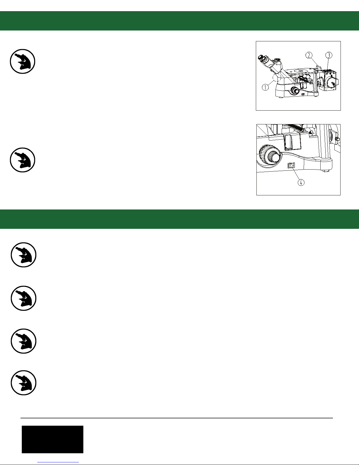
Slide the beam splitter (1) to direct light 20% to the eyepieces and
80% to the trinocular port (camera).
Slide the beam splitter the other direction to send light 100% to
the eyepieces.
Adjust the Diopters
Turn the coarse focusing knob and then the ne focus knob to get
a clear image while viewing through the left eyepiece only. Then
look through the right eyepiece. If the image is unclear rotate the
diopter adjustment ring (1).
There is a +/-5 diopter on the ring. The number shown on the
diopter (2) is your eye’s specic setting. Note the number that lines
up with the mark on the side of the eyetube (3). Remember this
number if multiple people are using the microscope.
Focusing
Place the sample on the stage and move the 5x objective into the
light path.
The surface of the sample should be perpendicular to the
objective.
Adjust the right diopter adjustment ring to “0” and look through
the right eyepiece. Adjust the coarse focus knob (1) and then the
ne focus knob (2).
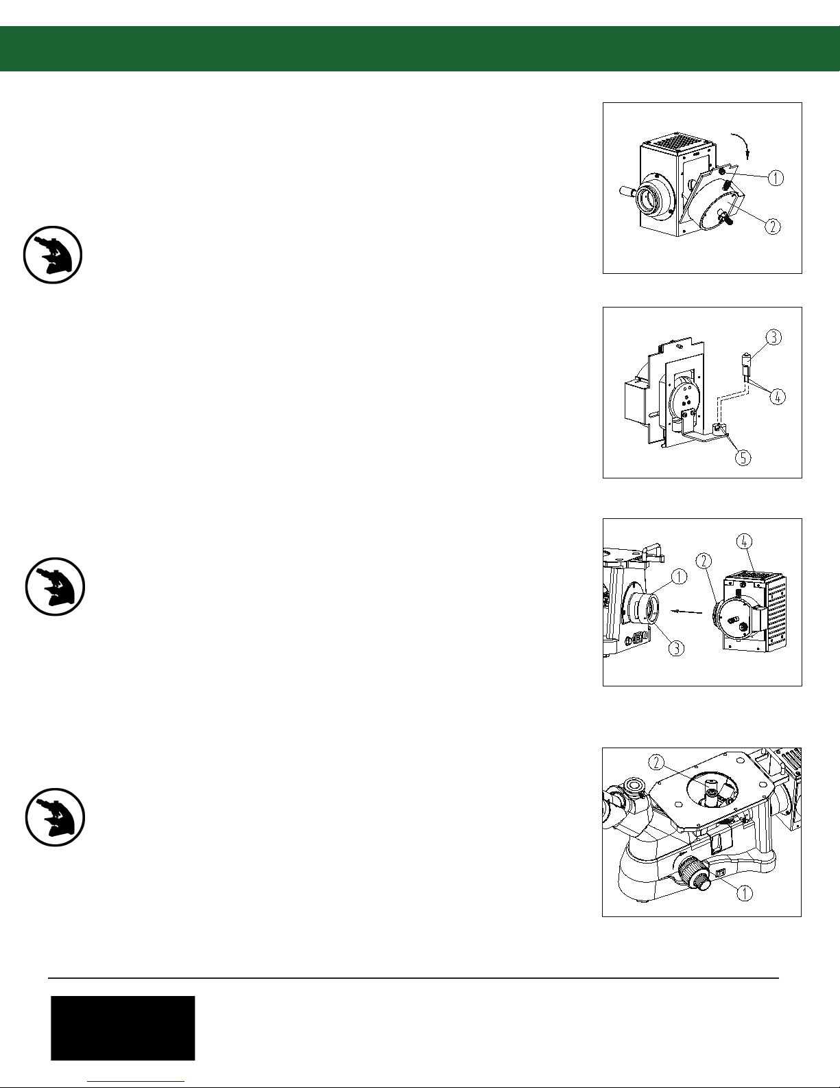
Adjust the Focusing Tension
If it is hard to turn the coarse focus knob or the sample falls out of
focus (the stage drifts), solve the problem by adjusting the focus
tension adjustment ring (1).
To tighten the focus mechanism turn the tension ring clockwise.
To loosen the tension turn it counterclockwise.
Adjust the Interpupillary Distance
When using both eyepieces, hold the base of the prism and rotate
them around the axis until there is only one eld of view.
The mark (1) on the side will line up with a number (2) that shows
your specic interpupillary distance. Remember this number if
multiple people are using the microscope.
Interpupillary adjustment range = 50~75mm.

info@feinoptic.com
Page 9
Microscope Operation:
Using the Eye Shields
If the user wears glasses, turn the eye shields down (1) to prevent
the glasses from touching the eyepiece and avoid damaging the
glasses or the eyepieces.
Open the eyesheilds (2) to prevent stray light from disturbing
observation.
Adjust the Field Diaphragm
By limiting the diameter of the beam of light entering the
condenser, the eld diaphragm can strengthen image contrast.
When the image of the eld diaphragm is on the edge of the eld
of view the clearest image is obtained.
Adjust the eld diaphragm rod (1) to minimize the eld
diaphragm. The image of the eld diaphragm can be seen through
the eyetube.
Adjust the right and left centering screws (2) on the eld
diaphragm until the image is centered.
Open the eld diaphragm slowly. If the image is inscribed in the
eld of view, the eld diaphragm has been centered properly.
Open the eld diaphragm slightly when using the microscope.
Use the Ground Glass Filter
When the ground glass lter slider (1) is pulled to the left it is used
to center the lament. When it is pulled to the right it will help
create uniform illumination. Typically this lter is set to the right in
the engaged position.
Use the Color Filter
The color lter (1) can make the background more suitable and
improve image reection. There are four types of color lters that
are typically used: blue, green, yellow and white.

info@feinoptic.com
Page 10
Microscope Operation:
Adjust the Aperture Diaphragm
The aperture diaphragm decides the numerical aperture (NA) of
the illumination. If the NA of the illumination matches the NA of
the objective, the best resolution is obtained with increased
contrast and depth of eld.
Adjusting the aperture diaphragm is the same as adjusting the
eld diaphragm.
Adjust the size of the aperture diaphragm for comfortable
viewing.
Using the Simple Polarizing Kits
The simple polarizing kit includes the polarizer (1) and the 360˚
rotating analyzer (2).
When using the polarizer remove the color lter from the light
path.
Dialing the turntable on the 360˚ rotating analyzer can change the
orthogonal states of the polarized light.
When the turntable on the analyzer is set to“0” the analyzer and
polarizer are in the orthogonal state.
Center the Light Filament
Adjust the lament to the center of the eld of view for even
illumination. Shift the ground glass slider (1) out of the optical
path until it clicks.
Set the eld diaphragm lever (4) and the aperture diaphragm lever
(5) to the left. Place a white piece of paper on the stage. Rotate the
nosepiece without an objective in it into the light path.
Adjust the halogen bulb horizontal adjustment screw (2) and the
vertical adjustment screw (3) to center the light. Adjust the focus
lock handle (6) to get a clear lament image, then center it in the
eld of view.
Pull the ground glass slider back into the light path and put a
sample on the stage, adjusting the focus knob for a clear image.
Observe through the eyepieces and once a clear, focused image is
obtained, lock the focus lock handle (6). Adjust the eld
diaphragm (4) and aperture (5) for comfortable observation.
Replacing the Fuse
Before replacing the fuse, make sure the power is switched to“O”
o and unplug the microscope. Use a screwdriver to remove the
fuse (1) from the fuse holder (2) and replace it with a new one.
Fuse: 250V, 3A

info@feinoptic.com
Page 11
Microscope C-Mount & Objectives:
LWD Plan Achromat
Semi APO
Brighteld
Objective Type Part # / Magnication Numerical Aperture Working Distance
FMPLN5 / 5x
FMPLN10 / 10x
FMPLN20 / 20x
FMPLN50 / 50x
0.15
0.30
0.45
0.55
10.8mm
12.2mm
4mm
7.9mm
BF-SAPO-M20 / 20x 0.50
0.80
0.90
3.2mm
1.2mm
1mm
BF-SAPO-M5 / 5x 0.15 19.5mm
BF-SAPO-M10 / 10x 0.30 10.9mm
BF-SAPO-M50 / 50x
BF-SAPO-M100 / 100x
Using the C-Mount Adapter
Loosen the set screw (1) on the trinocular port and remove the
dust cover (2).
Remove the dust covers from the c-mount adapter (3) and place
the c-mount on the trinocular port, tightening the set screw (1).
Loosen the set screw (4) on the c-mount adapter to remove the
c-mount (5). Connect the camera and then replace the c-mount
adapter.
Adjust the image through the eyepieces and then pull the beam
splitter to direct light to the camera. If the camera image is not
clear, adjust the c-mount focus (6) until the image is clear in both
the eyepieces and the camera at the same time.

Troubleshooting:
info@feinoptic.com
Page 12
Optical Troubleshooting
Problem Cause Solution
Light is bright, but eld of
view is dark.
Field diaphragm is not large enough.
Rheostat on light is turned down.
Polarizer or analyzer blocking light.
Open the eld diaphragm.
Adjust the rheostat.
Remove polarizer/analyzer.
Side of the eld of view
is dark or uneven.
Nosepiece is not clicked into position.
Stain or dust has accumulated on the
condenser, objective, eyepieces or light
source.
Rotate nosepiece into place.
Clean surfaces of condenser,
objectives, eyepieces and
light source.
Dust is observed in the
eld of view.
Dust has accumulated on the specimen.
Dust is on the objective or eyepiece.
Clean the sample.
Clean the objective and
eyepieces.
Image is not clear.
A cover slip is being used. Remove cover slip.
The sample is not vertical to the objective. Adjust sample.
Aperture diaphragm not open.
Clean eyepiece / objective.
Beam splitter is not in correct position. Adjust beam splitter.
One side of eld of view is
dark or the image moves
while focusing.
Specimen is not xed. Adjust sample on stage.
Nosepiece is not clicked into position. Click nosepiece into place.
Center the light bulb.
Light is not centered properly.
Eyes fatigue quickly
during use or the right
eld of view doesn’t
match with the left.
Interpupillary distance is not set properly. Adjust interpupillary distance.
Diopter adjustment is not set properly. Adjust the diopters.
Dierent eyepieces are being used in the
left and right eyetube.
Use the same eyepieces in each
eyetube. Use the Fein Optic
FPL-WF10x, FN22 Eyepieces.
Beam splitter is pulled out. Push the beam splitter in.
The lter, polarizer or analyzer is not in
position.
Remove / reinsert lters and
sliders.
Beam splitter is not in correct position. Adjust the beam splitter.
Adjust aperture diaphragm.
Stain or dust is on the lens.

Troubleshooting:
info@feinoptic.com
Page 13
Mechanical & Electrical Troubleshooting
Problem Cause Solution
Stage drifts or falls. Tension knob is too loose. Tighten tension knob slightly.
Power is not turned on. Check power cable connection.
Bulb is not installed properly. Check light connection.
Bulb is burned out. Replace Bulb.
The connector pins or the wires for the
bulb are not connected properly.
Check wire connections and
connector pins for the bulb.
Bulb ickers or the
brightness is not stable.
Coarse focusing knob is
too tight. Tension knob is too tight. Loosen tension knob slightly.
Light does not work.
Field of view is not bright
enough.
Rheostat adjustment is turned down. Adjust the rheostat control.
Bulb burns out quickly. Incorrect bulb is being used. Replace bulb with part #
R40POL-001.
Incorrect bulb is being used.
The bulb needs to be replaced.
Mechanical Troubleshooting:
Electrical Troubleshooting:
Replace bulb with part #
R40POL-001.
Replace bulb with part #
R40POL-001.
Problem Cause Solution

Bulb Replacement:
info@feinoptic.com
Page 14
Replacement Bulb for Mi40, 12v 50w Halogen = R40POL-001
To replace the bulb on the Mi40, unscrew the top
silver screw on the light housing as shown at
right.
The panel will open.
Remove the panel.
Depress the gold prongs as shown below and
insert the bulb using a glove or lens tissue paper
(do not touch the bulb).
Once the bulb is inserted (note the red arrows for
insertion point), release the prongs.
Replace the panel in the light housing.
Retighten the screw.
Table of contents
Other Fein Optic Microscope manuals